


Of the various types of applied energy processing, induction hardening is the most common. Induction heating is a process that uses an alternating electrical current that induces a magnetic field, causing the surface of the gear tooth to heat. The area is then quenched, resulting in an increase in hardness within the heated area. This process is typically accomplished in a relatively short time. The final desired gear performance characteristics are determined not only by the hardness profile and stresses, but also by the steel’s composition and prior microstructure.
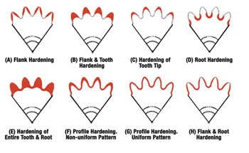
The hardness pattern produced by induction heating (Figure 1) is a function of the type and shape of inductor used as well as the heating method. Quenching or rapidly cooling the work-piece can be accomplished by spray or submerged quench. The media typically used for the quench is a water based polymer. The severity of this quenchant can be controlled by the polymers concentration. Cooling rates are usually somewhere in between what would be obtained from pure water and oil. In some unusual situations compressed air is used to quench the work-piece.
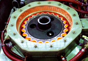
External spur and helical gears, bevel and worm gears, racks and sprockets are commonly induction hardened from steels such as 1050, 1144, 4140, 4150, 4350, 5150, and 8650. The most common methods for hardening gears and sprockets are by single shot (Figure 2) or the tooth-by-tooth method (Figure 3). Single shot often requires large kW power supplies but results in short heat/quench times and higher production rates. This technique uses a copper inductor (coil) encircling the work-piece. An inductor, which is circumferential, will harden the teeth from the tips downward.
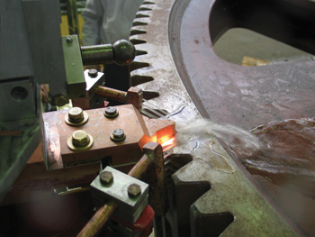
While the single shot method is acceptable for splines and some gearing, the larger heavier loaded gears where pitting, spalling, tooth fatigue, and endurance are an issue need a hardness pattern which is more profiled like those produced with carburizing. This type of induction hardening is called tooth-by-tooth hardening. This method is limited for gear tooth sizes up to 5 or 6 DP using frequencies from 2 to 10 kHz and about 10 DP using a range of 25 to 50 kHz. The lower the frequency; the deeper the case depth. This is a slow process due to the number of teeth and index times, and is usually reserved for gears and sprockets that are too large to single shot due to power constraints. The process involves heating the root area and side flanks simultaneously, while cooling each side of the adjacent tooth to prevent temper-back on the backside of each tooth (Figure 4). The induction system moves the coil at a pre-programmed rate along the length of the gear. The coil progressively heats the entire length of the gear segment while a quench follower immediately cools the previously heated area. The distance from the coil to the tooth is known as coupling or air-gap. Any variation in this distance can yield variation in case depth, hardness, and tooth distortion. The gear is indexed after each tooth has been hardened, often skipping a tooth. This requires at least two full revolutions in the process to complete the hardening of all teeth. Straight, spur, and helical gears up to 210”, 15,000 lbs. have been processed with this method. The entire process yields a repeatable soft tip of the tooth with hard root and flank. In other applications, the tip and both flanks can be hardened simultaneously and yield a soft root.
References:
- Herring, Daniel H. and Frederick J. Otto, Fred R. Specht, Gear Materials and Their Heat Treatment, Industrial Heating, September 2012.
- Rudnev, Gear Heat Treating by Induction, Gear Technology Magazine, March/April, 2000.


 general practice for CQI-9 and AMS2750E")


