


Gas turbines on land, air, and at sea experience some extreme environments, such as high airflow, pressure, and temperature. Engines intake air from outside and compress it to increase pressure ratio. Burning of fuel occurs in the combustor, where nozzles spray fuel to combust with compressed air uniformly to generate maximum heat. This process sees maximum temperature rise in the system, which puts limitations on material selection in terms of high temperature deformation, high temperature corrosion, and fatigue. The air intake and compression expose materials to erosion and wear. To protect engine parts from physical, chemical, and thermal damage, engine parts are coated with a variety of coatings. Furthermore, these coatings assist in increasing operating temperatures, thus increasing fuel efficiency.
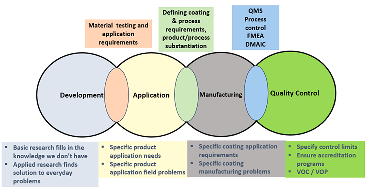
The understanding of a coating’s life cycle helps in streamlined, objective research and development, targeted application, effective and efficient manufacturing, and maintained process/product quality. The life cycle consists of research and development, application, manufacturing, and quality control, shown in Figure 1. The steps in life cycle phases support identifying technology, defining and prioritizing customer needs, translating them into critical part/assembly characteristics/target values, developing production equipment requirements, and establishing process control methods/parameters and inspection routine. The importance of standardized coatings testing, preparation, evaluation, and characterization technique is underestimated in some sectors, which has led to passing of a non-optimal coating and failing of a good one. Either scenario is unacceptable.
There are four main categories of coatings applied in gas turbines: thermal spray, overlay, diffusion, and environmental barrier coatings (EBC).
Thermal spray coatings are widely used in aerospace, nuclear, power generation, transportation, pulp and paper, petrochemical, oil and gas, medical, and automotive industries. Some of their applications are clearance control, thermal barrier, corrosion protection, wear resistance, decoration, dimensional restoration, etc. Thermal spray is a board term that encompasses many spray techniques based on energy source, particle velocity, state of feedstock, and spray mode.
Overlay coatings are applied onto a surface in a vacuum chamber or reactor. Feedstock of the coatings are wire, powder, rod, bulk material, and precursor gases.
Diffusion coatings are applied in a vacuum as well, but the thermodynamic equilibrium of the coatings-substrate materials shift resulting in adsorption of coatings material leading to diffusion of constituent elements from coating to substrate or substrate to coating.
EBC is applied onto a surface via thermal spray, air spray, as slurry, and in a chamber-like overlay coating. They are applied on metal substrates, ceramic matrix composites, and continuous fiber-reinforced ceramic composite combustor liners. These coatings protect substrates from high temperature oxidation up to 1,482°C (2,700°F), corrosion, wear, and water vapor recession.
A variety of methods used to apply these coatings is considered a special process in many industries, thus it must be substantiated before deployment and controlled afterwards. The life-cycle phases of these coatings are critical in ensuring that a knowledge base exists for understanding process and materials behavior, correct technology is chosen for a product/specific problem, process and coating requirements are established, and repeatability and reproducibility of the process is guaranteed.
Duration of a technology from inception to maturity to production can take five to 10 years. Coatings research and development consists of creation and development of new coating materials, creation and development of methods and processes for application, and understanding the interaction between coating systems and coating methods. It focuses on basic research to fill the knowledge we don’t have with the objective of solving everyday problems.
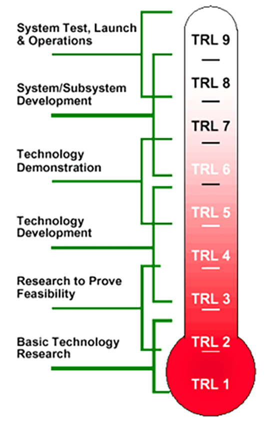
A structured technology readiness level (TRL), shown in Figure 2, and manufacturing readiness level programs that move through rigid tollgate phases are a necessity for technical competency, timely validation, and cost effectiveness. The TRL 1 indicates the beginning of research. Findings and understandings from preceding levels set the objectives of successive levels. Materials testing and evaluation play a vital role in understanding the materials science paradigm of processing, structure, property, performance, and characterization, which supports product validation. Some of the testing applicable to coatings are metallographic, bond strength — tensile and lap shear, hardness, erosion, oxidation, composition, wear, fatigue, corrosion — wet/environmental, and residual stress. At TRL 8, the technology is “flight ready” for application.
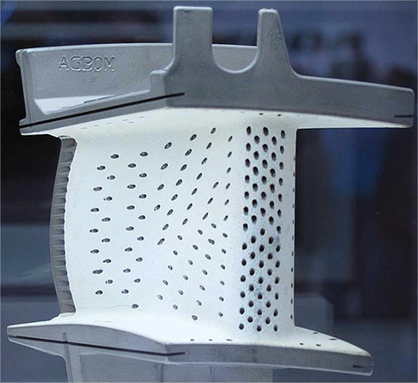
The application phase is focused on selecting a coating and method for a specific application on a product/part. A coated part used in gas turbines is shown in Figure 3. The selection of coating material and coating method are dependent on compatibility of the method on hardware, materials degradation issue that is being addressed, reproducibility, manufacturability, repairability of the coatings, cost, and field application. Leading a transition from R&D to product qualification/certification needs a disciplined approach. Part application development is run through a series of tollgates. The initial tollgate is to select a critical but low risk part, review equipment, funding levels, resources, and project timeline. A spray, test, repair, and part substantiation plan needs to be established before developing specifications and validation test and analysis. If there are any disconnects between controlled environment and field application, specifications need to address those concerns. Upon successful completion of application development, we are ready for the manufacturing phase.
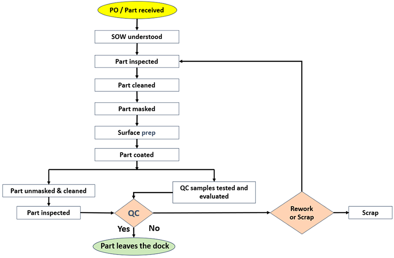
At this stage, the R&D and application team hands over projects to the manufacturing team. The manufacturing phase is driven by coating and application requirements. A typical coatings manufacturing process map is shown in Figure 4. A detailed value stream mapping will help a team in understanding the cycle time, changeover time, and takt time. The team should follow lean manufacturing methodology to minimize waste and drive efficiency. Lean methodology sees nine forms of waste with the acronym DOWNTIMES. D – defect; O – overproduction; W – waiting; N – non-utilized talent; T – transportation; I – inventory; M – motion; E – extra processing; and S – safety. To drive manufacturing excellence, manufacturing teams ought to minimize DOWNTIMES. Furthermore, going to Gemba, Kaizen, waste walk, 6S, Kanban, Poka-Yoke, and Cellular manufacturing principles in combination with Six Sigma methodology is deployed for optimal quality management system.
The quality control phase works in tandem with the manufacturing phase. Manufacturing processes need to be controlled and continuously managed to ensure that the process has not drifted. Six Sigma methodology will ensure effectiveness of the program. Failure Mode and Effect Analysis (FMEA), a risk management tool, is used to identify potential failure, anticipate consequence of failures, and mitigation. The severity of failure, frequency of occurrence, and detection ability must be understood to compute a risk priority number for effective corrective action. In coatings, the failure will arise from the coating method, surface preparation, coating performance, and the part. Statistical process control charts, such as individual range, moving range, subgroup average, and range of subgroup is applied to monitor a process and to improve it through elimination of assignable causes and reduction of process variability. Sigma level of current process is calculated, and a target sigma level is established based on Defects per Million Opportunity. Process capability indices, such as Cp and Cpk and Pp and Ppk measure short-term and long-term process stability, respectively. It also gives insight into how the process variation — voice of process (VOP) compares to the targeted specification/engineering variation — voice of the customer (VOC). Process capability is measured for coatings characteristics, such as porosity, unmelts per field of view, elemental composition, transverse crack per linear inch, oxides, thickness, grit embedment, bond strength, hardness, surface roughness — pre-coating and post-coating, extent of oxidation, erosion, wear, fatigue, etc. A Pareto chart must be constructed to identify the biggest contributors to problem(s). The contributors can be any one of the 6Ms: Man, Machine, Material, Method, Measurement, and Mother Nature. To confidently evaluate the extent of which contributor is causing the observed problem, Design of Experiment (DoE) is exercised by making purposeful, systematic changes. DoE can be deployed in all phases of the life cycle. We need to be careful that correlation does not mean causation. It is convenient to conclude that the effect of input variables is direct. Unfortunately, that is not the case for complex processes such as a coating’s application, testing, and evaluation. The effect can be due to the interaction of input variables. A full factorial DoE with resolution V designs can help identify that. Further, Analysis of Variance helps in understanding the significance of individual variable and interaction of variables at appropriate alpha levels.
The Define, Measure, Analyze, Improve, and Control (DMAIC) steps can be applied in all four phases in various forms to achieve targeted objectives. As the complexity of coating material, coating process, hardware, and environment increased, the DMAIC cycle has been modified to Define, Measure, Analyze, Design, and Verify the cycle as a part of the Design for Six Sigma practice. The Design for Six Sigma practice is being used for design/development, innovation, optimization, and validation of product/process to achieve effectiveness. The methodologies, principles, and techniques presented here are applicable and can be employed in many other industries, such as heat treatment, materials processing, etc.
Reference
- Olivier Cleynen, CC BY-SA 3.0 <https://creativecommons.org/licenses/by-sa/3.0>, via Wikimedia Commons


 general practice for CQI-9 and AMS2750E")


