


Eddy current is a nondestructive testing technique proven for use in heat treatment and material structure verification. Modern multifrequency eddy current instruments can test for conditions such as misplaced case, shallow case, short heat, short quench, and delayed quench.
Gears, bearings, axles, shafts, and other components are heat treated to develop the required strength and durability. Heat treatment is a critical process in the manufacture of powder metallurgy components to produce the necessary performance properties for good service life in tough applications. Heat treatment in a furnace (e.g., carburizing) and by induction heating are used to harden selected areas such as gear teeth, which are subjected to high stresses in service.
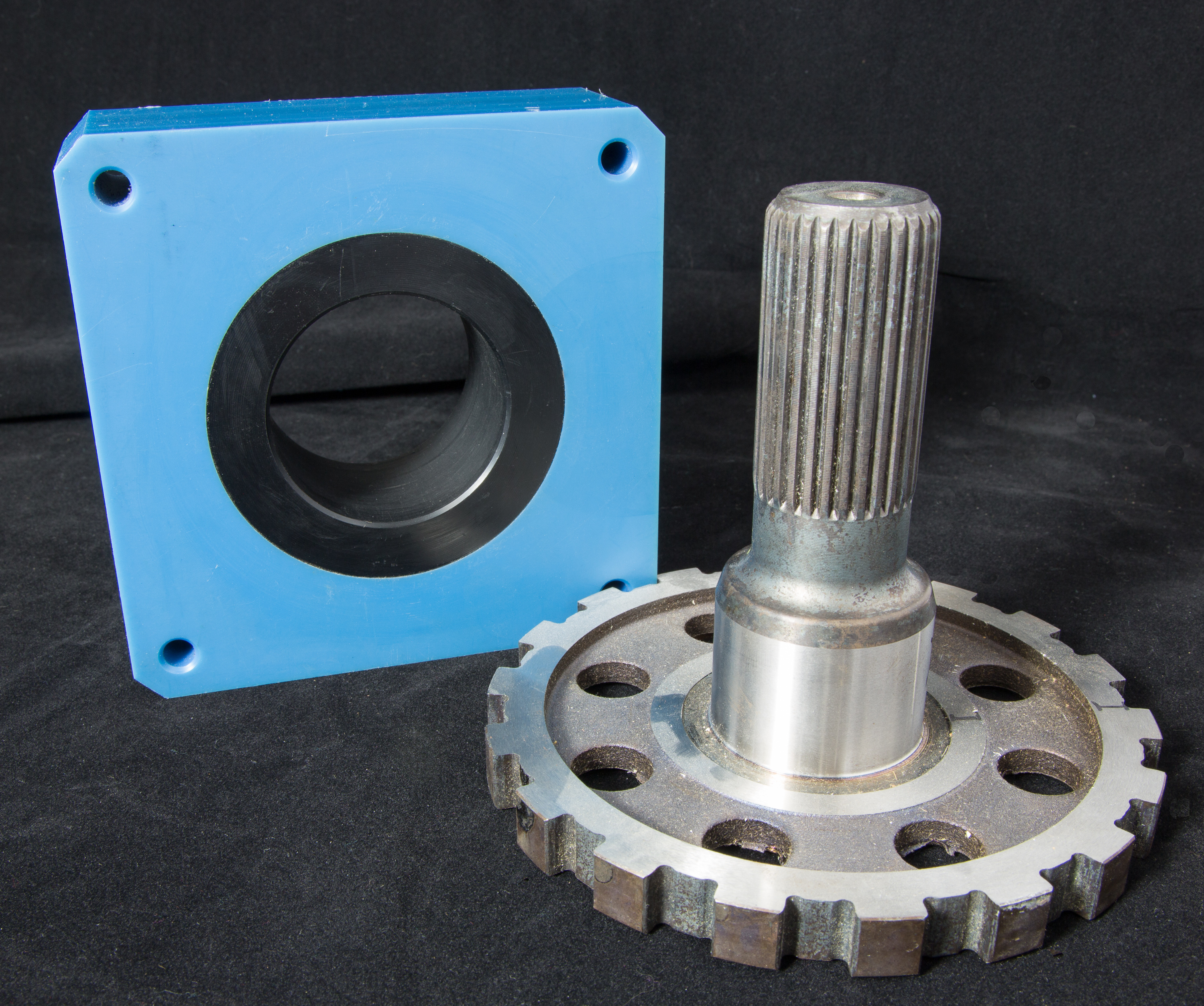
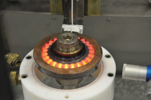
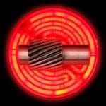
Figure 1 shows a complex component consisting of a spline and gear and an eddy current coil used to test the component. For this component, the spline area may be hardened differently than the base gear area. The eddy current coil is sized to test just the spline area. To test the base, a separate larger diameter probe is required.
For parts having complex heat treat patterns, microindentation hardness testing of every part manufactured is not feasible. Rockwell hardness testing only identifies whether heat treatment results are satisfactory in the area being inspected. In addition, hardness testing leaves indentations on the part surface. Heat treatment verification is often impossible to detect using visual methods.
Compared with traditional testing methods, eddy current testing offers a fast, reliable, and repeatable method to determine whether a part has been heat treated according to specifications. Eddy current testing is a comparative test, so it does not provide hardness data but does indicate whether the part differs from a known standard (a master or group of reference standards).
Eddy current testing is based on electromagnetic induction, which was discovered by Michael Faraday in 1831. In the late 1800s, it was discovered that properties of a coil change when it is placed in contact with metals of different conductivity and permeability. In the 1950s and 60s, the technique became widely used in testing aircraft and nuclear power plant components. In the past 20 years, it has been extensively used to test components for proper heat treatment and material structure.
Eddy current systems used to verify heat treatment consist of an electronic instrument and a set of coils. Eddy current coils are usually encased in a protective structure, the entire system known as an eddy current probe. Coils are typically wrapped around the component being tested in a manner similar to a coil wound around the core of transformer.
During actual testing, two sets of coils are used — one wrapping around a reference master and one wrapping around the component being tested. Coils are driven at various test frequencies, and differences in coil responses are measured by the eddy current instrument. The component being tested is considered out of tolerance if the differences exceed a preset threshold.
Probe design considerations
Similar to the principles of transformer design, it is important to have coil windings in close proximity to the component. It is also desirable to have a good fill factor, i.e., the component area versus the coil area.
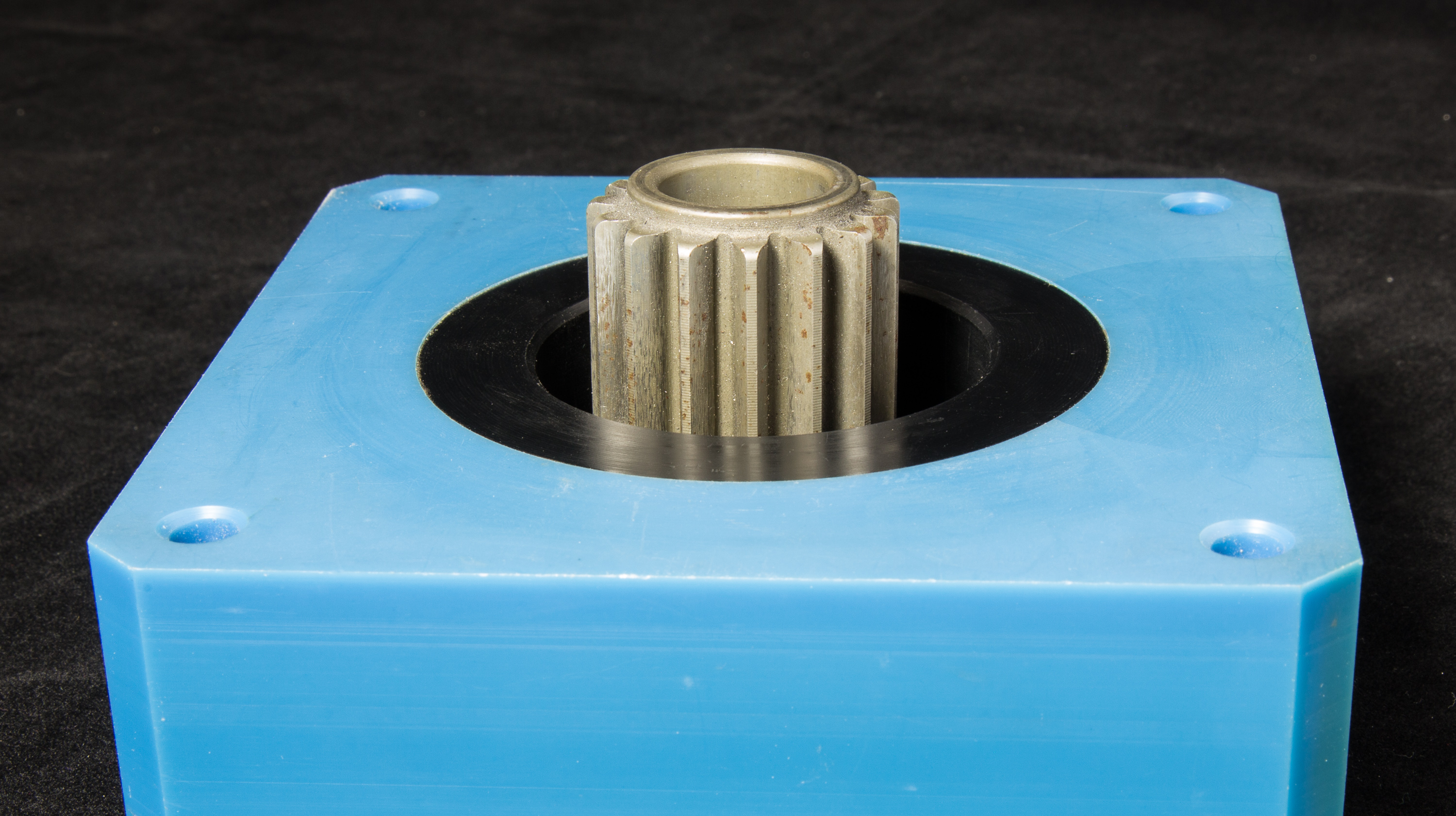
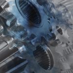
Figure 2 shows how a part being tested typically fits inside an eddy current probe. The probe must align consistently (keeping a consistent coil-to-component distance) with every component. Typically, a polymer material (such as nylon) is used to insulate the winding from the component, and in a high-speed production environment, a stainless steel sleeve is often used to prevent damage to the insulating material and the coil.
Probe mechanical fixturing
For handheld testing, an eddy current probe is placed over the part. However, in a production environment where every part is tested, testing must be automated.
Automated eddy current testing systems are usually integrated into the production assembly line. This allows testing to be carried out in an online versus offline process, simplifying production flow. Testing stations are usually installed immediately downstream of the heat treating process, which enables flagging heat-treat process failures, such as a failed induction heating element and clogged quench ring, in real time.
The time to run the actual eddy current test is usually a couple of hundred milliseconds. When the test is complete, the probe is raised off the part. If the part passes the test, it moves down the conveyor to the next station in the production line. If the heat-treated condition falls outside acceptable parameters, the eddy current instrument communicates to the material-handling station via industrial I/O to send the part to a “reject” chute or bin. If consecutive rejects occur, the eddy current system can send an indication to the line supervisor informing them of a possible process error.
Advanced robotics considerations
Traditional assembly-line fixturing consists of a conveyor to move parts in and out of the test cell, a mechanism to secure the part under testing, a probe actuator that can move the probe up and down, a sorting mechanism, and a reject chute or bin.
Mechanical work cells typically designed specifically for each test are efficient, robust, and have a small footprint. They are controlled via PLCs that interface with the eddy current system electronics.
Traditional mechanical work cells have some disadvantages. They are typically dedicated to a specific line and part. Any changes to the line or part require a redesign of the system. Systems can be costly and could take months to design, build, test, and install.
An alternative to a dedicated work cell approach is to use a robot that engages the part with the eddy current probe, moves untested parts into the work area, and moves tested parts out of the work area. Parts that fail the test are moved to a separate location without the need for complex sorting chutes and mechanisms.
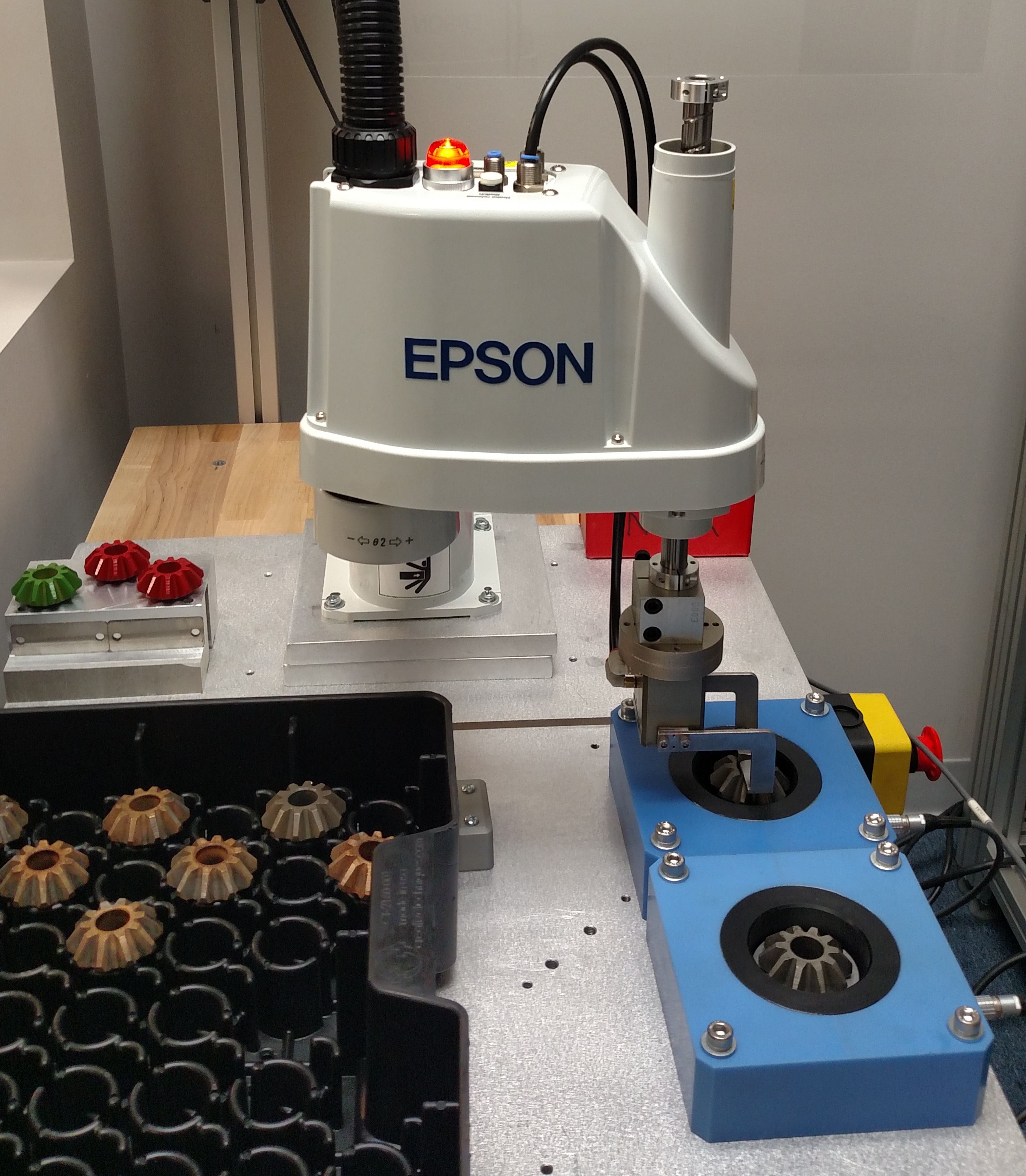
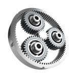
While the concept of using robots on assembly lines is not new, the decreasing prices of smaller robotic arms make them more attractive for this type of application. Figure 3 shows a SCARA-type robot from Epson Robots (Carson, California) and a demo test station set up to test differential cam/side gears. The robot places a part into the eddy current coil closest to the robot, and a second eddy current coil holds a reference master, which is used as part of the differential test.
In traditional work cells, tests are loaded by hand and are usually validated at the beginning and end of each shift. With an automated system, verification can be done more frequently if desired.
Robot systems usually consist of a robot, a gripper, and a controller. Teaching a robot to perform the required tests is typically simple. The robot arm is moved to a specific location and the point is programmed. All locations where the robot will travel are recorded in this manner.
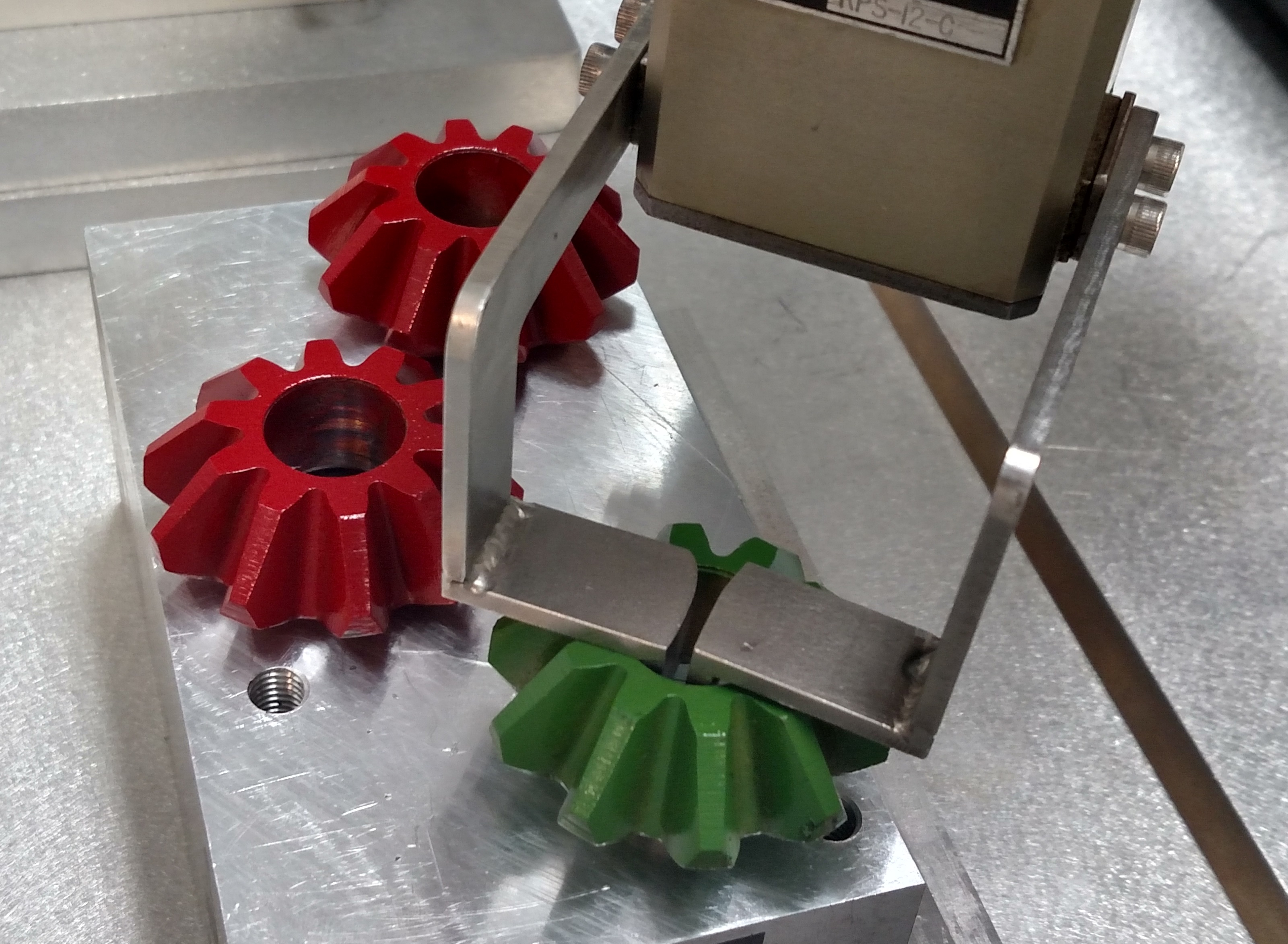
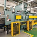
Figure 4 shows a unique gripper used to pick up and place gears. Grippers can be custom configured or manufactured to accommodate different component types.
Advantages of using robotics
Advantages of using robots like a SCARA over a traditional testing cell include flexible design parameters, ease of reconfiguration, and ease of calibrating the eddy current system.
Flexible design parameters
Inspection of complex shapes often requires complex eddy current probes or multiple probes connected to multiple instruments. Using a robot, multiple locations are inspected by simply moving the probe to a new location. Test parameters are usually changed using configuration-switching features in the eddy current test instrument.
Easy to reconfigure
If a design or inspection criteria changes, it is easy to reconfigure or reprogram the robot. The eddy current probe can be redesigned if additional eddy current testing locations are required. If a standard eddy current probe can be used, the probe is moved to the additional location.
Easy-to-calibrate eddy current systems
Eddy current systems used on production lines are periodically checked using masters that have known post-heat-treatment conditions. With conventional eddy current testing systems, the operator inserts a master into the production flow and verifies the test or “nulls” the machine to the good part. This is often done at the beginning and end of a shift. With a robotic system, the robot can be programmed to periodically pick up a master and check it or null against it. Operator intervention is not required.
In simple applications and in applications that have a very high line speed, a dedicated system can deliver better performance than a robot. The actual size of a dedicated cell may be smaller than a line using a robot.
Options to consider in a trade-off study between the two approaches include:
- Speed of production line
- Complexity of the part
- Number of inspections performed on each part
- Expected life of the production line
- Time to implementation
In either case, simplified electronic interfaces on eddy current instruments, PLCs, and robots make it easy to implement an eddy current test solution.


 general practice for CQI-9 and AMS2750E")


