


Selective laser sintering (SLS) is an additive manufacturing technique that builds 3D models layer-by-layer using a laser to selectively melt cross sections in powdered polymeric materials, following sequential slices of the CAD model. SLS generally uses thermoplastic polymeric powders, such as polyimides (i.e. nylon), and the resultant 3D objects are often weaker in their strength compared to traditionally processed materials due to the lack of polymer inter-chain connection in the z-direction. Previous efforts showed the challenges of printing a melt- processable RTM370 imide resin powder terminated with reactive 4-phenylethynylphthalic anhydride by LS, due to its inherently low viscosity of these oligomers. This paper presented the first successful 3D printing of high temperature carbon fiber filled thermoset polyimide composites, followed by post cure cycles to promote additional crosslinking for achieving higher temperature (Tg = 370°C) capability. The processes to build tensile specimens and a component by LS, and the characterization of RTM370 imide resin by DSC and rheology as well as evaluation of the LS printed polyimide composite specimens by SEM and mechanical tests will be discussed.
1 Introduction
Selective laser sintering (SLS) is an additive manufacturing technique that builds 3D models by using a laser to selectively melt a cross section in powdered polymeric materials layer-by-layer, following the slice of each computer-aided design (CAD) scan. The most commonly used polymers for SLS are polyamides 11 and 12 powders with use temperature ranged from 150-185°C [1-2]. Recently semi-crystalline PEEK of varied LS-grade powders, with a melting temperature (Tm) of 343-370°C, have to be heated to 380°C to be manufactured into 3D objects by a more elaborate high temperature LS (HT-LS) machine and process to afford products with a glass transition temperature (Tg) of 150°C [3-4]. However, the 3D objects build by these thermoplastic polymers are often weak in their strength compared to traditionally processed materials due to the lack of polymer inter-chain connection in the z-direction. There are attempts to process epoxy resin by SLS [5] or impregnating liquid epoxy into green parts built by SLS using polyamide mixed with carbon fiber [6]. However, the real incentive of developing a SLS process for thermoset resins lies in the potential of raising the use temperature to 250-300°C for 3D-printed objects and the prospect of printing polymer carbon fiber composites for aerospace applications. Previously we reported the challenges of attempting to print a melt-processable RTM370 imide resin powder terminated with reactive phenylethynyl (PEPA) groups into thermoset polyimides by LS [7].
As described in previous reports, we realized the viscosity of resin designed originally for resin transfer molding (RTM) was too low, and the laser apparently only melted the resin without curing the reactive PEPA endcap. As a result, the LS-printed resin chips could not hold much integrity upon postcure above 250°C. To overcome the low viscosity of the resin, the standard RTM370 resin was further staged for 2-4 hours at 300°C to promote chain extension while still maintaining melt-processability and avoiding extensive crosslinking of PEPA endcap.
2 Experimentation
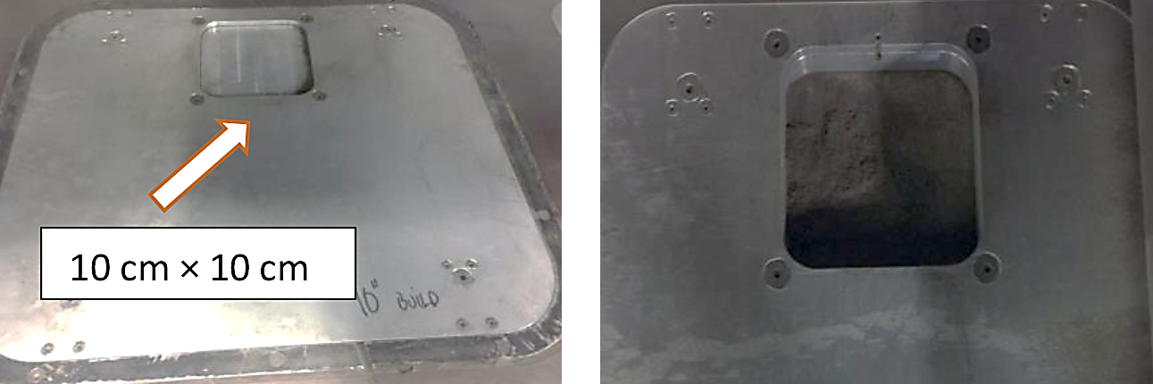
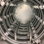
Standard RTM370 resin produced by Imitec Inc. was further staged for 2-4 hours at 300°C to promote chain extension while avoiding extensive crosslinking of the PEPA endcaps for use in LS. Short carbon fibers (length ∼60µ) were obtained from Advanced Laser Materials, LLC (now part of EOS North America). Carbon fiber (35 wt%) was added to the RTM370 resin further staged at 300°C for three hours, and then dry blended in a rotating drum tumbler to ensure a consistent blend. To save the materials used for this LS study, SinterStation 2500 was retrofit with a small 10 x 10 cm build chamber (Figure 1) out of the original build piston. Both the build piston/cylinder and the feed cartridges would need to be modified. The temperature of the part bed is monitored and controlled by an infrared sensor. The temperature of the feed cartridge is also measured by a thermocouple. The rheology was performed in the parallel plate geometry with 1g of imidized powder at a ramping rate of 4°C/min and frequency at 10 rad/sec, using an Ares Rheometer. The differential scanning calorimetry (DSC) was conducted on TA Instruments Q1000 with 5°C/min heating rate. The thermal conductivity was measured on a C-Therm TCi thermal conductivity analyzer. AccPyc II Pycnometer by Micromeritics was used to measured porosity in LS disk.
3 Results and discussion
3.1 Laser Sintering of RTM 370 Resin
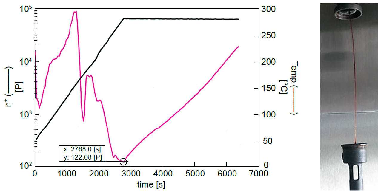
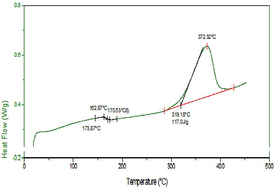
Our previous attempt to produce durable resin chips by LS using “as received” RTM370 powder indicated that its viscosity (~30 poise) was too low for LS, because it was originally designed for resin transfer molding (RTM) application. Therefore, RTM370 resin was further staged at 300°C for 2.5 hours to afford a resin with higher viscosity, indicative of higher chain extension as evidenced by the formation of a filament inside the rheometer (Figure 2). A DSC thermogram showed a Tg of ∼170°C and a PEPA endcap curing at 372°C (Figure 3).
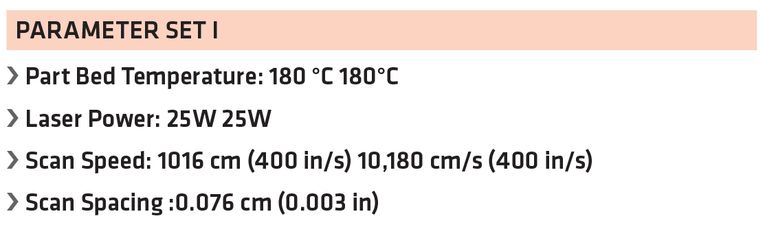
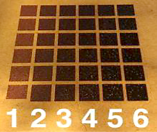
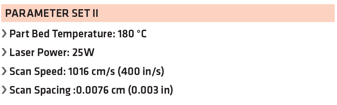
Using the parameter listed in Table 1, several sets of 6 resin chips (1-6 scans) were produced by LS using further staged RTM370 resin, and they appeared very uniform (Figure 4). However, when warming to 200°C in an oven, the resin chips appeared to soften. Then the chips started to melt and lose integrity when reaching 250°C, indicating that the PEPA endcaps probably have not been fully cured.
3.2 Laser Sintering of RTM 370 /Carbon Fiber Composites:
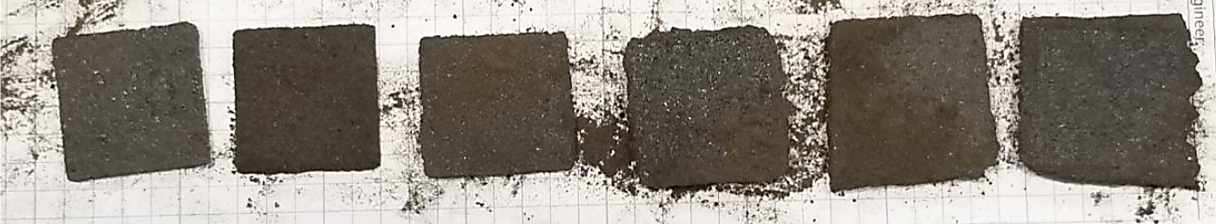
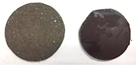
To improve the stiffness of the build layers, RTM370 resin was mixed with 35 percent carbon fibers (∼60 µl in length) and dry blended for printing composite specimens by LS. The single layer square samples all scanned successfully (Table 2) and exhibited greater green strength (Figure 5) than any of the neat resin with or without further staging at 300°C in previous LS runs. It is believed that the filled carbon fibers not only provide the stiffness but also significantly improve the heat transfer to the resin/fiber mixture on the powder bed upon irradiation of the laser. The depth of penetration (chip thickness) also increased with a greater number of scans, although a DSC thermogram still showed significant exotherm of the uncured PEPA endcap at 370°C, indicating that the green composite disks are not fully cured yet. The thermal conductivity of the carbon fiber-filled RTM370 LS disk in Figure 6 (0.6 W/m.K, porous) is almost three times that of a neat resin disk (0.2 W/m.K, dense). The porosity of the LS disk is ∼54% based on gas pycnometer measurement.
3.3 Laser Sintering of Composite Specimens:
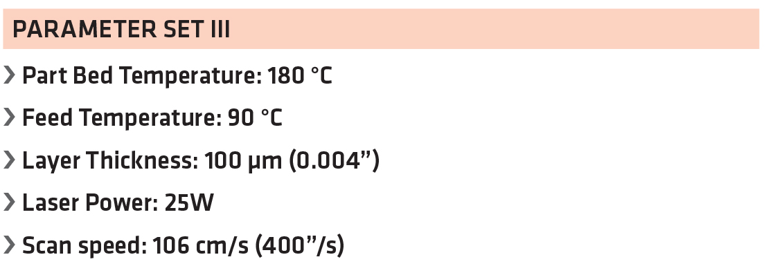
I) 100 µm Thickness Layers: With the success of producing the single scan composite chips with integrity, the objective shifted to focus on building composite specimens and parts by LS. The initial build parameters used is listed in Table 3.
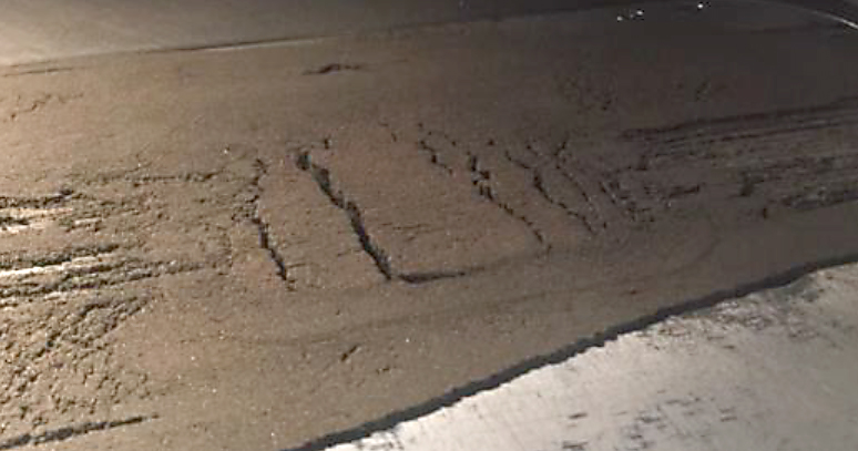
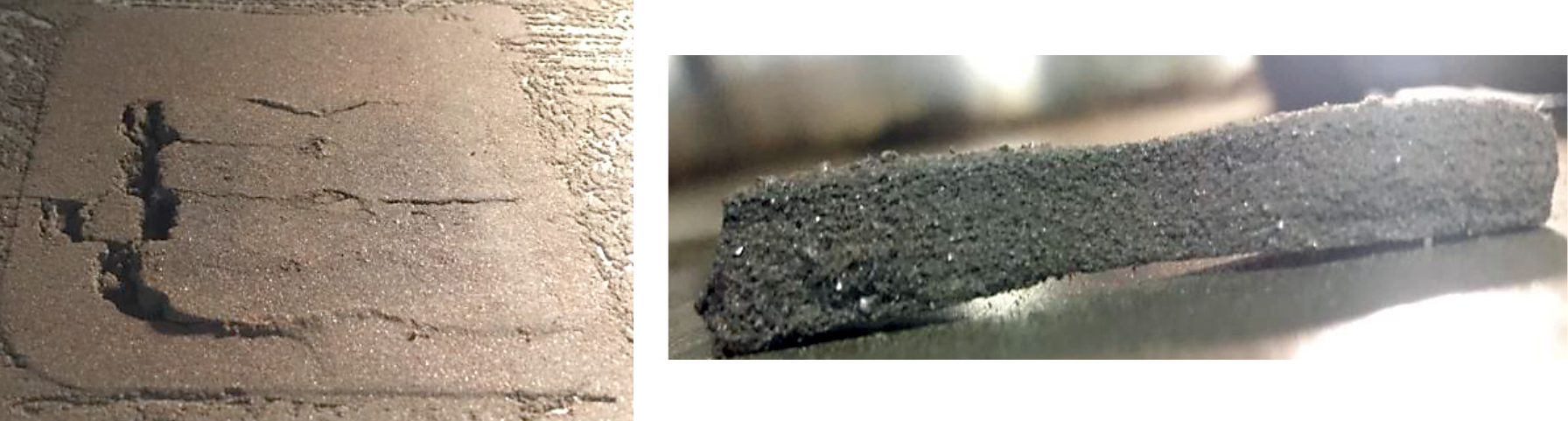
A layer of material was spread across the build platform and heated up to the specified temperature to observe changes in state. During the addition of a powder layer, the material was not rolling well in front of the roller/spreader but instead was “bulldozing.” Due to the change in the location of the thermocouple to control the feed temperature, it was thought that the powder may be overheating. Over several build attempts, the feed temperature was dropped to 70°C, and the feed heater output limit was dropped from 60 percent to 20 percent to prevent the feed area from melting. If the temperature of the feed powder gets too high, it can cause the powder to agglomerate and/or melt. An indicator of the powder temperature getting to high is the feed bed “cracking” shown in Figure 7.
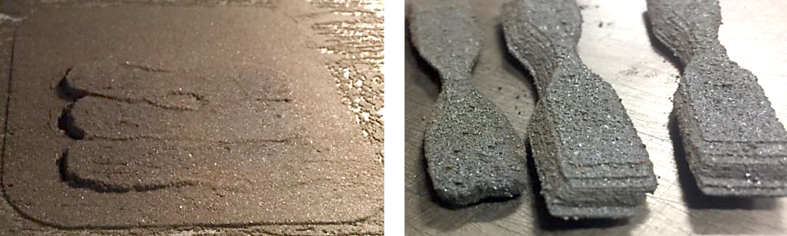
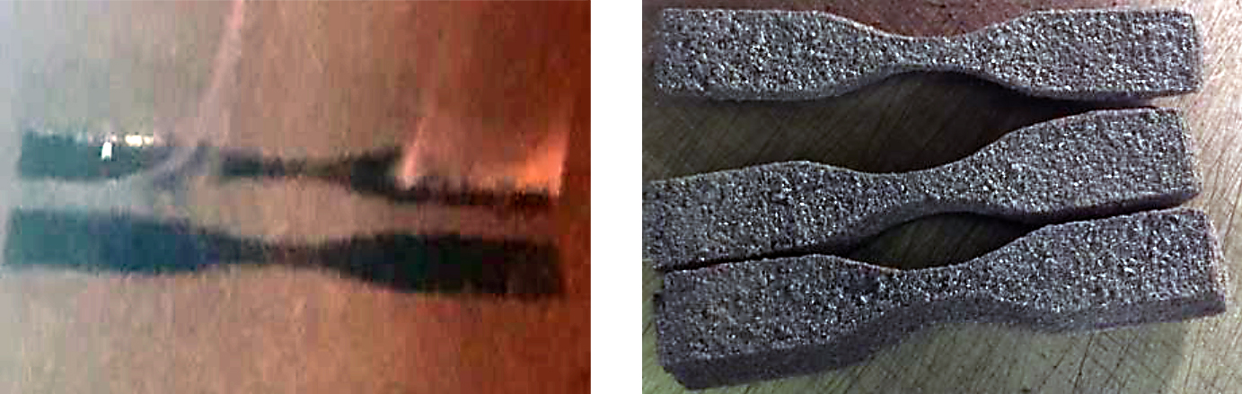
A number of builds were attempted at these conditions, but in all cases, the layers would shift as the roller/spreader assembly moved across the build area. The layer shifting can also be caused by shear forces generated between the previously melted layer and the new powder being applied to the build area. This is most evident when the material does not roll easily and instead bulldozes. This shifting is shown during the build and post-build in Figure 8.
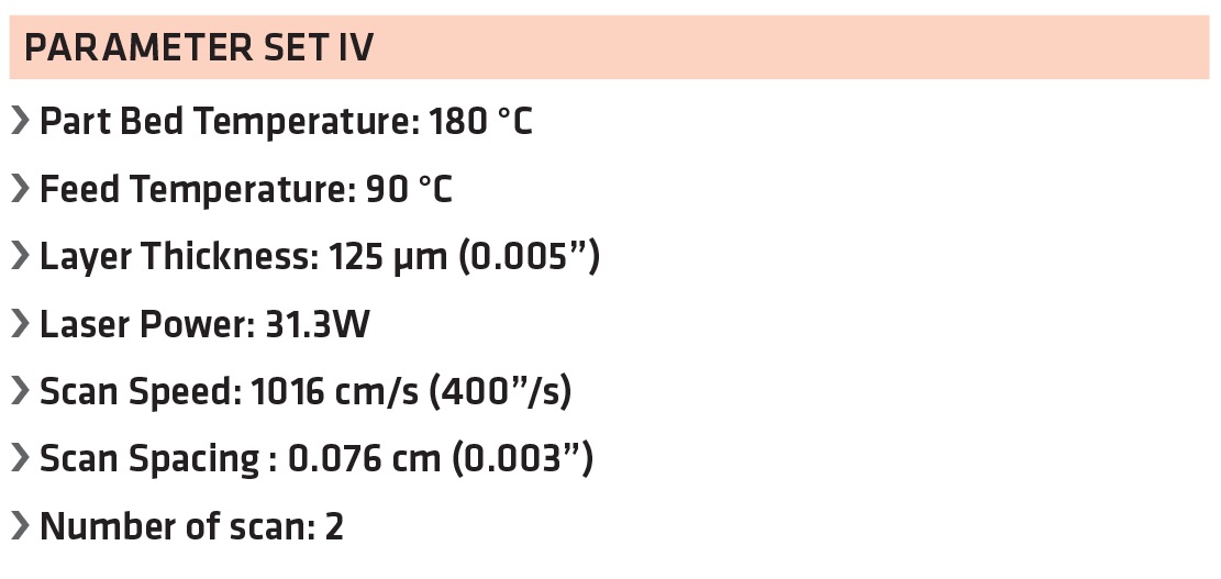
II) 125µm Thickness Layers: To build thicker layer, the laser power was increased to 31W, (Table 4) and multiple runs of tensile bars were attempted. More layers could be successfully completed compared to the 100µ layer builds.
The layer shifting was decreased, but warping and curling was seen during the build. Curling is generally a temperature issue caused by non-uniform cooling that contributed to parts curling or warping like a banana in the build area (Figure 9). The part then “rocks” as the roller/spreader assembly moves across the part bed.
It was determined that the curling may be due to the lack of dedicated part piston and cylinder heating in the small build volume retrofit. The machine would be preheated for 2-4 hours at the set temperatures to allow for all of the metal parts to come to equilibrium and heat soak in an attempt to minimize curling. While the curling was becoming much less visible, there was still layer-shifting occurring.
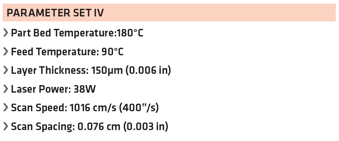
III) 150 µm Thick Layers: The layer thickness was increased to 150 µm, and the experiments were repeated by increasing the laser power to 38W (Table 5). With the modified feed cartridge, it was difficult to keep the thermocouple precisely located to just below the surface of the powder. This resulted in issues with consistent feed-temperature control. However, a number of subscale tensile specimens (Figure 10) for postcure and mechanical tests were successfully 3D printed, along with a few round disks (25 mm diameter x 2 mm thick) and 0.6 cm cubes printed for characterization using the parameters listed in Table 5.
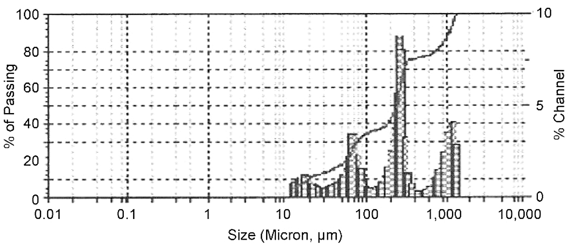
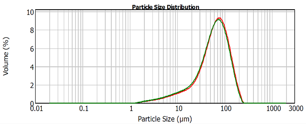
IV) Particle Size Analysis: A particle size analysis was conducted on the carbon-fiber-blended material. It was noticed that two new peaks appeared at 254 µm and 1,054 µm (Figure 11), relative to the original batch of RTM 370 powder with a single peak at 70 µm between 40-120 µm prior to further staging at 300°C (Figure 12). These are likely due to agglomeration of resin particles after additional staging/heating, as well as carbon-fiber entanglement during the dry blending of the fiber with resin powder. The surface roughness of LS-printed composite specimens may be the result of uneven particle size distribution/agglomeration as compared to the more uniform neat LS disks. The layer thickness would be increased to account for the difference.
3.4 Characterization of LS-Printed Tensile Specimens
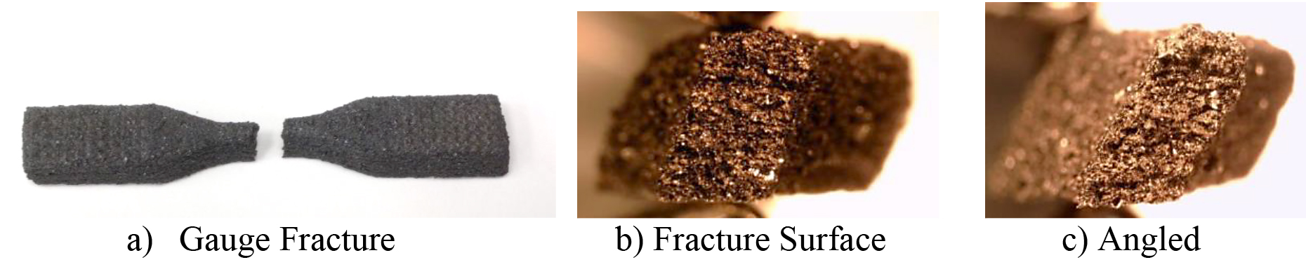
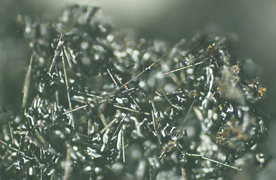
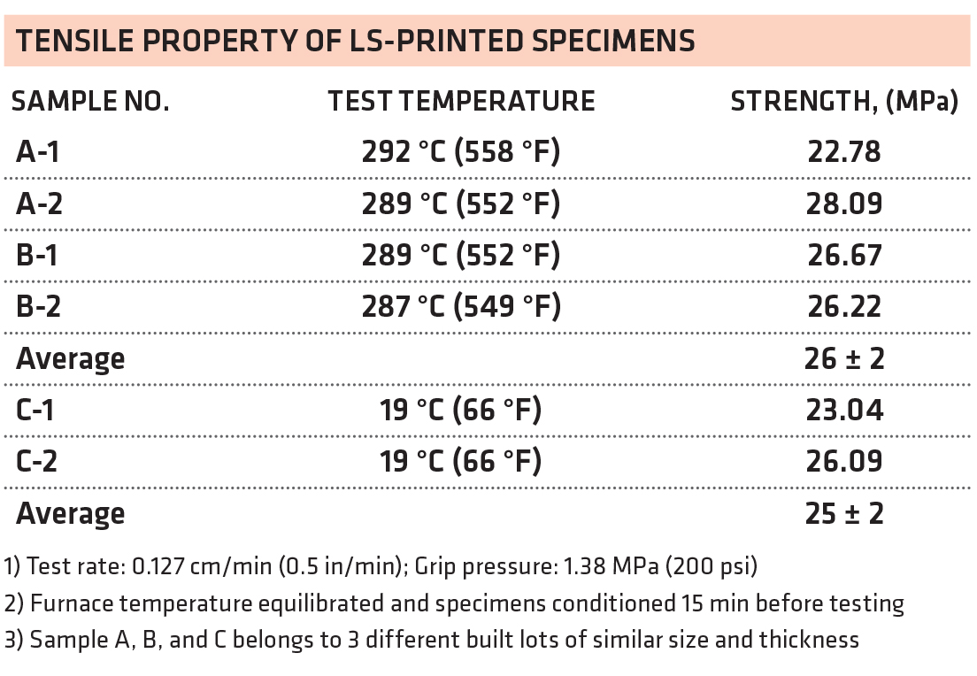
Half a dozen dogbone subscale specimens (6.5cm x 0.9 cm x 0.5cm thick, neck width 0.3 cm) were printed following the protocol described in the previous section. The as-print specimens were subjected to multi-step gradual temperature rise (3-5°C/min) and constant temperature holds with final post-cure at 343°C (650°F) for 16 hours in order to complete the total cure of PEPA endcaps and achieve optimal mechanical properties. A test of dogbone specimens misbehaved when testing at room temperature. However, all tensile testing at 288°C (550°F) fractured nicely at the mid-section of dogbones as shown in Figure 13a-13c, and a SEM micrograph of the fractured LS-printed composite (Figure 14) revealed milled fibers were incorporated into the LS-printed specimens. Furthermore, Table 6 indicated that the samples retained similar tensile strength at 288°C as well as at room 19°C.
3.5. Laser Sintering of Composite Parts
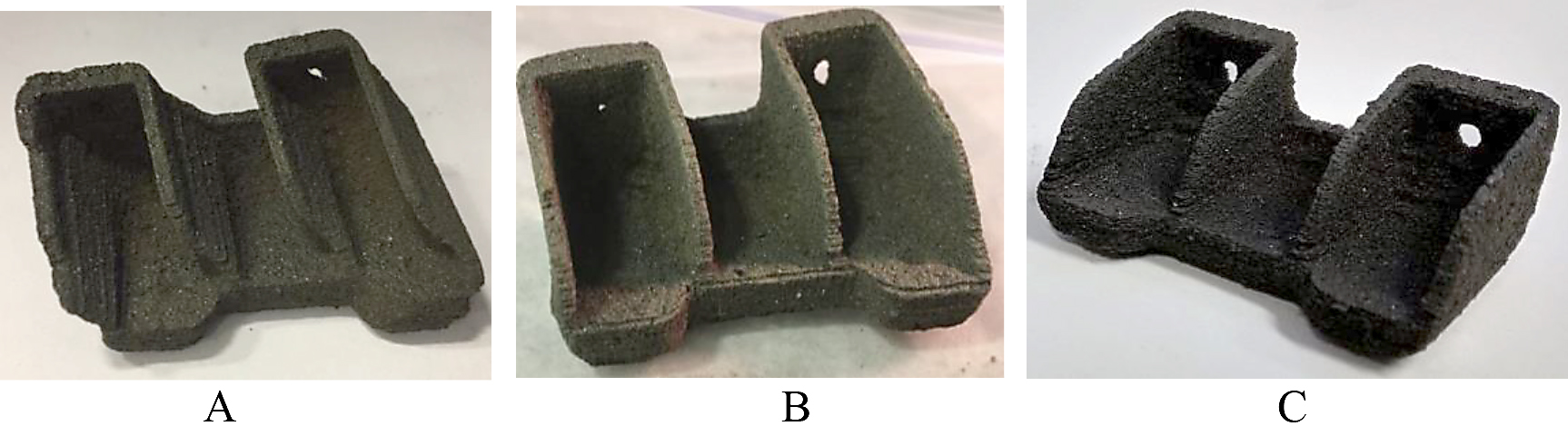
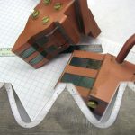
Following the success of printing composite specimens at 150µm thick layers, efforts began to focus on printing subscale components such as a bracket, using the same parameters. Initially the bracket was attempted to be constructed at a 50 percent scale. The part was able to complete, but the warping and shifting were too much to consider it a successful part. (Figure 15a). Using longer heat soak times helped somewhat, but not until there was full thermal control in the piston and cylinder heater temperature control as well as the overhead part bed heating (Figure 15b). Eventually, the 30 percent scaled geometric bracket was built well as successful 3D components by LS (Figure 15c). The “green” bracket was subjected to multi-step post-cure cycles by heating gradually at 3-5°C/min from room temperature along with multiple holds at steady temperature for an extended period of time and a final post-cure at 365°C for 16 hours to complete the total curing of a PEPA endcap to form a crosslinked network, while avoiding a dimensional change due to softening at an elevated temperature during the process. No noticeable dimensional change was observed in the post-cured parts. This is the first known high-temperature polyimide composite parts (Tg = 370 °C) printed by laser sintering in the additive manufacture field that can be used for >300°C aerospace applications.
4 Conclusion
This project was initiated to determine if laser sintering can be applied to high-temperature thermoset polyimides to enhance covalent bonding between layers through the curing of the reactive endcaps, as compared to conventional thermoplastic polymers that display poor z-directional mechanical properties. A melt-processable RTM370 imide resin originally designed for resin transfer molding (RTM) [8] and resin film infusion (RFI) [9] was dry blended with 35 wt% finely milled carbon fibers and used as a feedstock for laser sintering. Using a laser power of 25-38W and a bed temperature of 180°C along with a feed temperature of 80°C, tensile specimens and subscale composite brackets were successfully printed into green parts (not fully cured) by laser sintering. The filled carbon fibers apparently impart not only the stiffness but also higher heat transfer efficiency to enable building thicker layers, as compared to the neat resin in the LS process. To complete the total cure of the PEPA endcaps, the green parts were subjected to slow, multiple-stage, post-cure to form a fully crosslinked network as the final parts without any significant dimensional change. Essentially, a thermoset polyimide composite 3D network was achieved by using melt-processable imide oligomers terminated with reactive PEPA endcaps for LS processing. To the best of our knowledge, this paper demonstrates the first major advance in the additive manufacturing of high temperature polyimide composites with glass transition temperature (Tg) of 370°C printed by LS. Another advantage of this major breakthrough is that these thermoset oligomers can be 3D-printed by a regular laser sintering machine, without the need of using the high temperature laser sintering process (HT-LS, 250-380°C) required for processing commercial thermoplastic PEEK with 150-185°C use temperature. In essence, this research ushers in a new era of using additive manufacturing to produce high temperature thermoset polyimide composite parts for >300°C applications.
Acknowledgements
The authors would like to acknowledge the funding support from Air Force Research Labs at Wright-Patterson Air Force Base in Dayton, Ohio, for this project. In addition, we would like to thank the staffs at Rapid Prototyping Center at the University of Louisville, Kentucky, for conducting the laser sintering and Linda McCorkle and Daniel Scheiman of Ohio Aerospace Institute for performing the rheology, thermal analysis, and thermal conductivity. Furthermore, the team effort from the University of Dayton Research Institute (UDRI), including Thao Gibson’s contribution in cure characterization, Andrew Abbott and Ron Trejo’s help in mechanical testing and Marlene Houtz’s X-ray CT, are greatly appreciated.
References
- David K. Leigh: “A Comparison of Polyamide 11 Mechanical Properties between Laser Sintering and Traditional Molding”, Proceedings of Solid Freeform Fabrication Symp. 574-605 (2012).
- R. D. Goodridge, C. J. Tuck, R. J. M. Hague: “Laser Sintering of Polyamides and Other Polymers”, Progress in Materials Science, 57(2), 229-267 (2012).
- S. Berretta, K. E. Evans, O. Ghita: Processability of PEEK, “A New Polymer for High Temperature Sintering”, European Polymer Journal, 68, 243-266 (2015).
- S. Brretta, Y. Wang, R. Davies, O. R. Ghita: “Polymer Viscosity, Particle Coalescence and Mechanical Performance in High Temperature Laser Sintering”, Journal of Materials Science, 51(10), 4778-4794 (2016).
- WO2017046132, Le-Huong, Nguyen: “Use of thermosetting Polymeric Powder Composition.”
- WO2016127521, Chune Yan, Wei Zu, Yusheng Shi, Jie Liu: “3D Printing Manufacturing Method of Short fiber Reinforced Thermosetting Resin Composite Product.”
- Kathy C. Chuang, Timothy Gornet, Hilmar Koerner: “Challenges in Laser Sintering of Melt-Processable Thermoset Imide Resins”, Proc. of CAMX Conference, September 26-29, Anaheim, CA (2016).
- K. C. Chuang, D. M. Revilock, J. M. Pereira, J. M. Criss, Jr., E.A. Mintz: “High Temperature RTM370 Polyimide Composites Fabricated by RTM: Characterization and Impact Testing”, SAMPE Journal, 40(5), 48-57 (2013).
- Kathy C. Chuang, Thomas A. Yip, Ronald B. Kollmansberger, Thomas K. Tsotsis: “Evaluation of RTM370 Polyimide Composites by Resin Film Infusion”, SAMPE Technical Conference, June 2-5, Seattle, WA (2014).
This paper is declared a work of the U.S. Government and is not subject to copyright protection in the United States. It was presented at the Composites and Advanced Materials Expo; September 23-26, 2019, in Anaheim, California.


 general practice for CQI-9 and AMS2750E")


