


High-pressure gas quenching (HPGQ) is touted as a way to reduce distortion of difficult-to-quench geometries. Quench pressures and quench gas flow velocities are chosen to impart the slowest cooling rate, while still achieving the desired mechanical properties. While it is true that HPGQ imparts a more uniform method of heat extraction when compared to liquid quenching [1-2], due to convective cooling only, that does not necessarily mean less distortion of the component. However, a more uniform quench can result in more consistent distortion. Liquid quenching can lead to inconsistent results due to the chaotic nature of the vapor blanket and the unpredictability of the vapor blanket’s degradation into nucleate boiling [2]. Uniformity in this instance is in reference to the heat transfer coefficient witnessed by the surface of the component, not the heat flux through the surface. The heat flux out of the part is a combination of the heat transfer coefficient and the component geometry.
Assuming this heat transfer coefficient can be made perfectly uniform on all surfaces, geometric features will still create nonuniform cooling scenarios [3]. These nonuniform cooling conditions can create nonlinearities in the distortion response of certain geometries. This article will explore one such geometric feature: an eccentric bore. Such a feature should immediately stand out as difficult to quench due to the non-balanced mass distribution.
Geometry and Finite Element Model
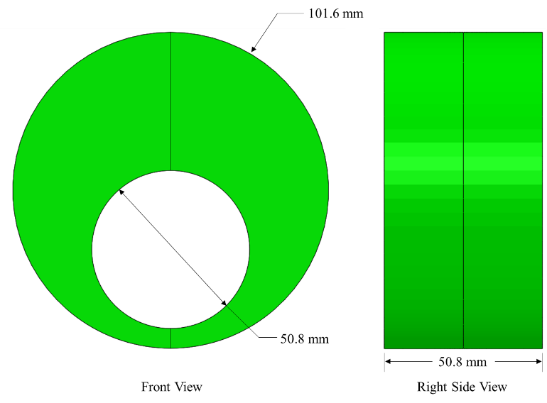
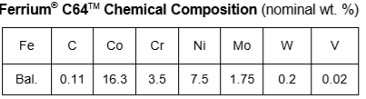
A 50.8 mm thick, 101.6 mm diameter disk, with a 50.8 mm eccentric bore was used for the modeling study, as shown in Figure 1. The thinnest cross-section measures 6.35 mm. The thickest cross-section measures 44.45 mm. The geometry was chosen for the nonuniform heating/cooling which occurs due to the nonsymmetric mass distribution. The disk is made from Ferrium® C64TM. The chemical composition of Ferrium C64 is shown in Table 1. Ferrium C64 was chosen for this study due to its high hardenability, negating the distortion effect of different phases forming from different cooling rates.
Process Description
Using the DANTE heat-treatment simulation software, the disk was subjected to a range of possible HPGQ HTCs: 10, 25, 50, 100, 200, 300, 400, 500, 600, 700, 800, 900, and 1000 W/m2K. Generally, HTCs of 200, 400, 700, and 1000 W/m2K correspond to quench pressures of 2, 6, 10, and 20 bar, respectively. However, this relationship will vary depending on the flow pattern and velocity profile of the quench gas in the vessel and around the component.
Distortion from Common Gas Quenching Rates
The distortion mode of interest for this study was out-of-round of the eccentric bore. The distortion was determined by the difference of the distances B1-B2 and A1-A2, as shown in the Figure 2 inset. Figure 2 shows the results from the study, plotted as out-of-round distortion (μm) versus HTC (W/m2K).
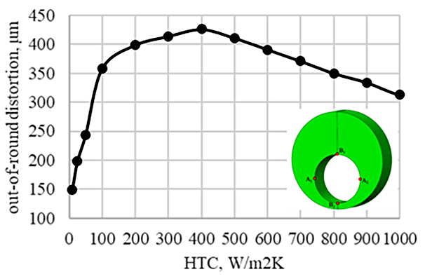
It is commonly assumed that if a component is quenched slower; i.e., a lower HTC value, less distortion will occur. As can be seen in Figure 2, the highest HTC nearly produced the least amount of out-of-round distortion. The only HTCs that produced less distortion in this case can be associated with an air cool (10, 25, and 50 W/m2K). The most distortion occurred from an HTC of 400 W/m2K, which is approximately equivalent to a six-bar quench.
HTC Comparison
A comparison between three HTC values — 100 (HTC100), 400 (HTC400), and 1000 (HTC1000) — during the martensite transformation is needed to understand why HTC400 results in more distortion than HTC1000. From an analysis of the model results, it was determined that the bore becomes distorted due to the martensite transformation stretching the bore in the vertical direction as the transformation proceeds from the thin to thick section. The distortion can be offset by transformations occurring simultaneously in the thin and thick sections. This behavior can be witnessed in the three cooling rates, with seemingly minor differences resulting in significantly different results.
Even though the transformation appears similar between HTC400 and HTC1000, as shown in Figure 3, there are two major differences that contribute to the increased distortion of HTC400. First, there is a steeper transformation gradient from the surface to the core for HTC1000, resulting in less transformation per volume around the bore, when compared to HTC400. Second, there is transformation occurring in the thick section of HTC1000 while the bore is transforming. This behavior helps offset the elongation of the bore that leads to the out-of-round distortion. The distortion is a maximum in HTC400 because the transformation is relatively uniform from the surface to the core, but there is a steep transformation gradient in the circumferential direction. This behavior means that HTC400 transforms large volumes of material as the transformation front progresses around the bore, incrementally stretching the bore.
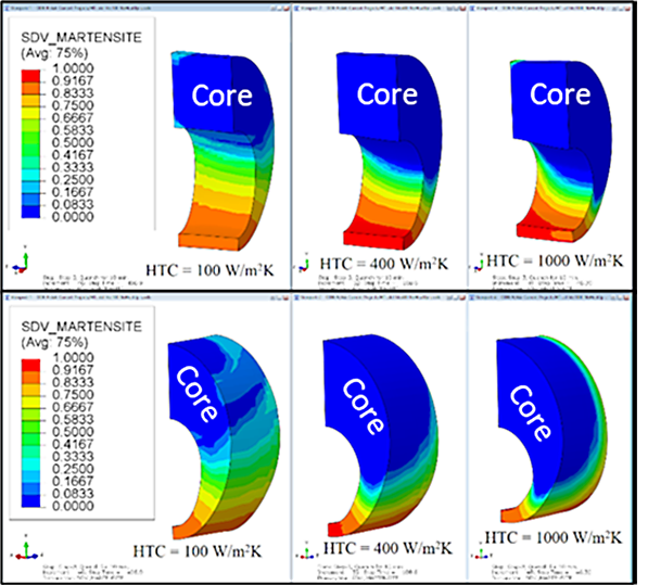
HTC100 shows a substantial amount of martensite transformation occurring in the thick section as the bore is transformed, with a very shallow transformation gradient in the circumferential direction. It is this behavior, the transformation happening almost simultaneously throughout the part, that leads to reduced distortion.
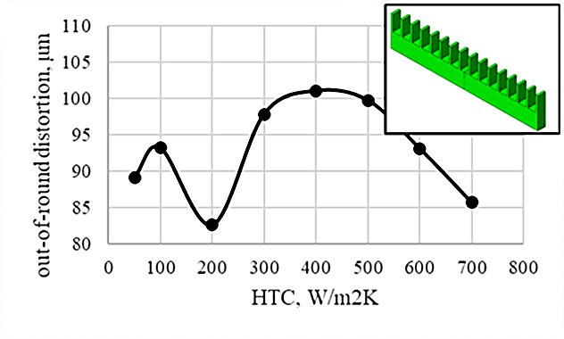
Another difficult-to-quench geometry is shown in the inset of Figure 4. This geometry cools much faster on the side with the fins, due to the increased surface area provided by the fins. This geometry also has a nonlinear distortion response to uniform heat transfer coefficients in the range of HPGQ, as shown in Figure 4. The distortion evaluated for this case was bow distortion of the coupon in the longitudinal direction. This example shows that nonlinear responses to high pressure gas quenching are not unique to the geometry presented in the study but exist in most difficult to quench geometric features.
The study presented here shows there is no easy way to determine a suitable gas pressure and velocity profile when turning to high-pressure gas quenching to reduce distortion in difficult-to-quench geometries. While an understanding of the mechanisms responsible for particular distortion modes is critical in the decision-making process, the ability to evaluate numerous conditions before any parts are processed should not be underestimated. The out-of-round distortion, and any shape-change distortion, is mainly due to the nonuniform, solid-state phase transformations, both to and from austenite. If nonuniformities cannot be avoided due to geometric features, the slowest rate possible should not automatically be considered to result in the least amount of distortion. Finite element modeling of the heat-treatment process, using software such as DANTE, can help the engineer choose the proper gas-quenching process parameters to ensure mechanical properties are achieved while keeping distortion to an absolute minimum.
References
- V. Heuer, K. Loser, and D.R. Faron, “Low Distortion Heat Treatment of Transmission Components”, AGMA Technical Paper, October 2010.
- Tim Yu, Tony Yu, and D. Herring, “Low-Pressure Carburizing and High Pressure Gas Quenching”, Heat Treating Progress, September/October 2003, p 37-41.
- Z. Li, “Heat Treatment Response of Steel Fatigue Sample During Vacuum Carburization and High Pressure Gas Quenching Process,” Proceedings of MSEC2015, Charlotte, NC, June 2015.


 general practice for CQI-9 and AMS2750E")


