


Heat treaters all over the world encounter similar problems with atmosphere furnaces. These problems not only cause operational headaches in the daily lives of furnace personnel; they significantly affect the bottom line. The most common is creep distortion of alloy components under carburizing conditions, eventually leading to catastrophic failure. This paper explores both conventional and alternative material options. We will discuss what causes furnace component failure, and commercially available improvements or substitutes.
The practical selection of alloys for atmospheric heat treating processes and alternative materials like monolithic ceramics and ceramic composites, is an important topic for the heat treating industry. INEX introduced silicon-silicon carbide (Si-SiC) composites in 1988 and has developed valuable perspective on the selection of metal alloys and competitive materials for trays, baskets, fixtures, belts, chains, and, of course, our main product focus in radiant tubes. Metal alloys and ceramic components used for the industry’s most common heat treating process, carburizing, are subjected to very high temperatures, substantial mechanical stress and severe atmospheric corrosion.
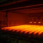
An estimated 80% of all heat treating activity is carburizing-related processes. Metallurgically, carburization not only occurs intentionally in the heat treating load, but unintentionally on a repeating or continual basis in the furnace’s metal alloy components. Belts and chains experience particularly hard mechanical duty since they see high tensile stress on a continual basis. However, radiant tubes experience the most severe thermal service since they see continual duty at the highest temperatures, typically 200°F (110°C) above than the process setpoint, as needed to transfer sufficient heat by thermal radiation.
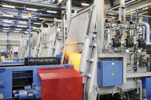
Combustion occurring inside radiant tubes also subjects the metal or ceramic to continual oxidation since burners operate with typically 10% excess air. This implies an oxygen content of approximately 2% in the combustion exhaust gas at 1750°F (954°C) or higher.
While it is important to review the process conditions that furnace components experience in Carburizing, we must also understand the corrosion and thermo-mechanical performance of the various material options available. Alloy and ceramic producers provide substantial data to support well-informed choices for process reliability and low life-cycle cost. Significant performance factors to review include 1) carburization resistance, 2) oxidation resistance, 3) creep stress (deformation), and 4) creep rupture. This data provides insight into the practical issues that affect lives of heat treaters every day.
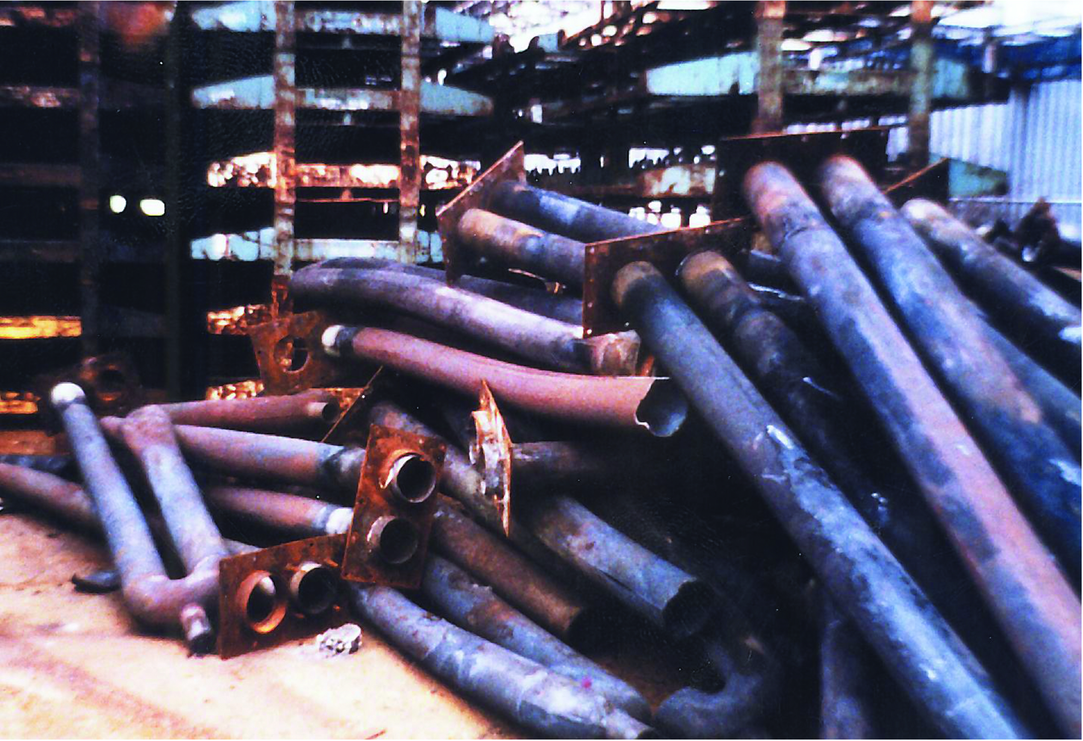
Figure 1 dramatically shows what we typically deal with: relatively short service life and corresponding high life-cycle cost of expensive alloys that creep, distort, and rupture in just a year or two. Staring at this scrap pile a feeling of hopelessness engulfs us and real improvement seems impossible; often we just install another tube or tray or belt and move on. The famous remark attributed to Albert Einstein comes to mind: “Insanity is doing the same thing over and over again, and expecting different results.” Are there superior alloys, or alternative materials such as composites and ceramics that may perform even better than metals, available to improve both lifetime and life cycle cost?
There are subtle and often substantial differences in each heat treating operation; sometimes even between furnaces which do similar processing in the same facility. Metallurgical objectives, load materials, part size and shape, equipment design and condition, atmospheric gases, and process temperatures vary considerably in carburizing processes. And it is not unusual for the same furnace to be used for a number of other heat treating processes. For example, carbonitriding loads frequently share a furnace that is otherwise used for carburizing. The point is there is no such thing as a universal heat treating furnace, and likely no single, best materials’ choice for trays, baskets, fixtures, belts, chains and radiant tubes.
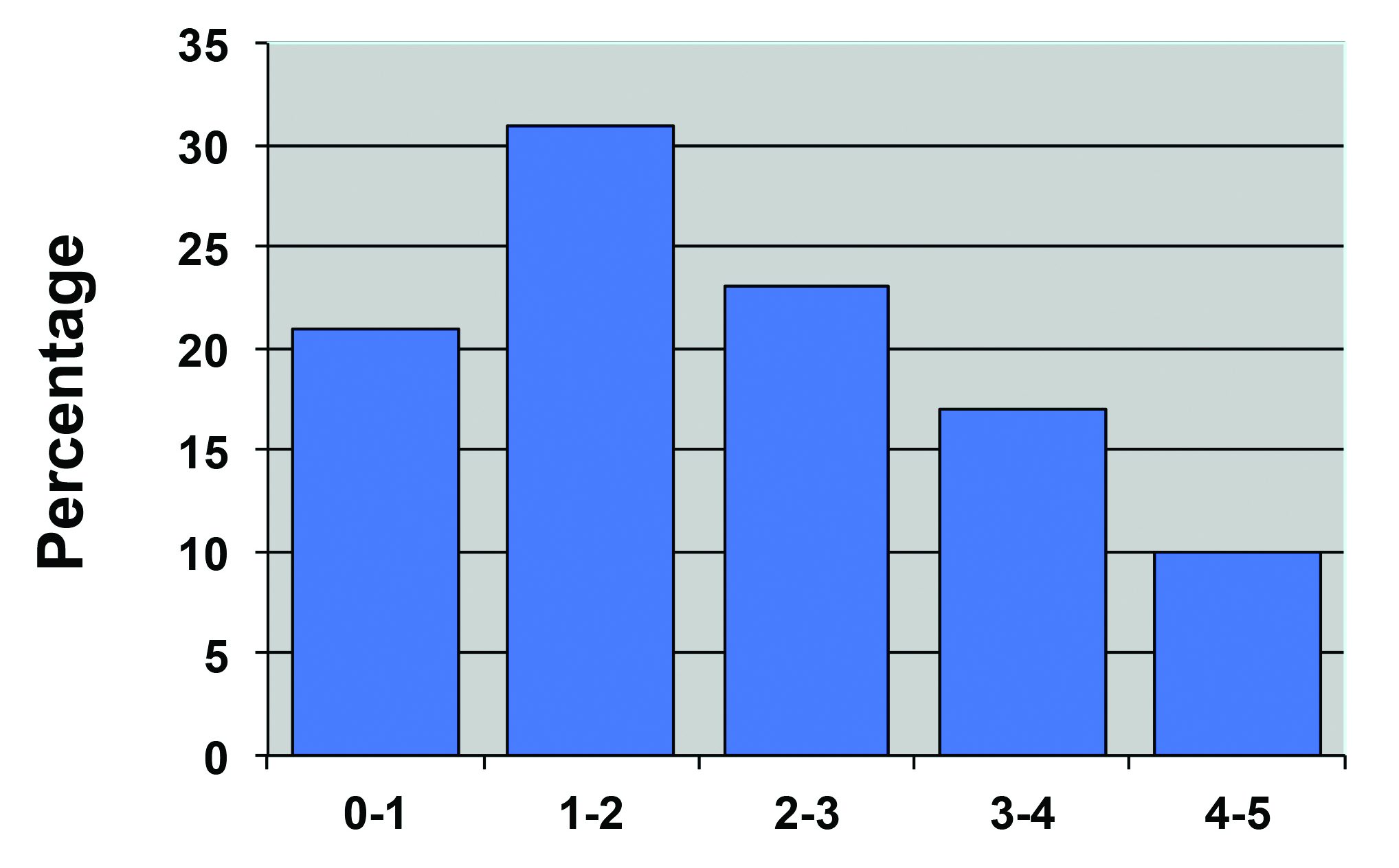
Figure 2 presents a service-life survey of all types of radiant tubes conducted by the Gas Research Institute in the mid 1990s (the most recent data available). This survey did not differentiate between radiant tubes used for carburizing and those used in less aggressive heat treating processes or mixed service. The tubes lasting up to two or three years were probably carburizing for a large percentage of the time. Those with life over three years likely saw lower temperature operation and more neutral atmospheres in service. Unfortunately, similar data is not available for other furnace components.
Atmospheric Corrosion
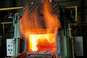
In atmospheric carburizing the furnace interior is subjected to highly reducing conditions — a carbon-rich, high temperature environment typically fed by endothermic, methanol/nitrogen or similar gas sources. Over an extended period carbon diffuses further and further into the metal surface seriously embrittling the tray, belt or radiant tube. Selecting a higher nickel content alloy may decrease the rate of carburization, but at higher material cost and an increased creep rate as we’ll see later.
Figure 3 shows a variety of heat resistant alloys commonly used for trays, baskets, fixtures, belts, chains and radiant tubes. The left column shows the most common cast alloys with compositionally similar wrought “equivalents” shown in the column at the right. The relatively newer alumina-dispersed APM and AMPT alloys (hot-pressed and extruded) are also included.
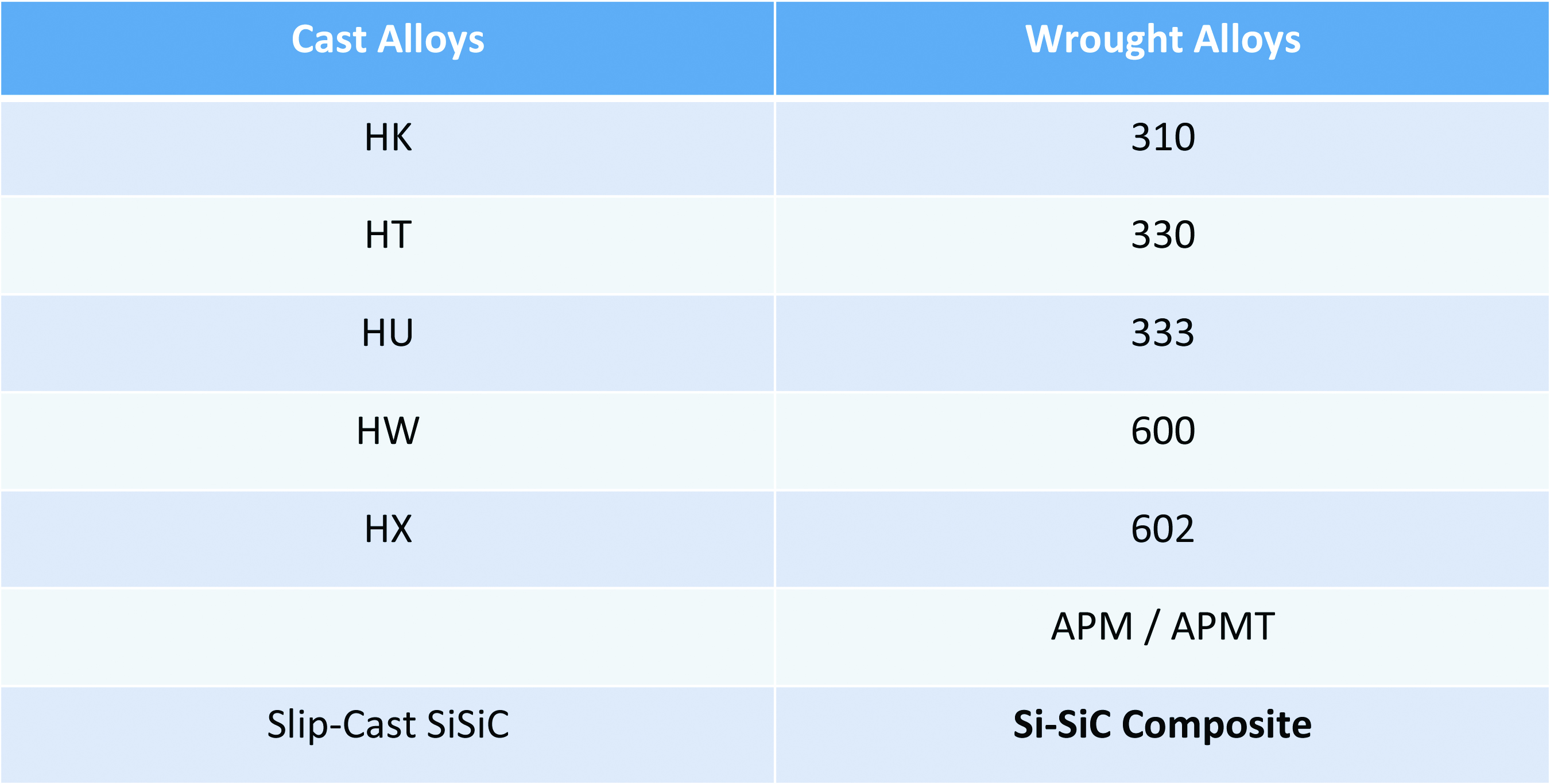
At the very bottom are two types of silicon carbide ceramics: Slip-Cast SiSiC available from a variety of suppliers, and Si-SiC, a unique metal-matrix-composite (MMC) which is formed by melt-infiltration. INEX Si-SiC composite consists of 50 volume percent elemental silicon forming a continuous metal matrix, reinforced by independent SiC particles. Slip-Cast SiSiC is a reaction-bonded, monolithic ceramic where some of the volume is filled with free silicon metal. Monolithic SiSiC ceramics are usually more expensive than Si-SiC composites, and both are used interchangeably. The high free silicon content of both the Si-SiC composite and monolithic SiSiC ceramics makes these materials immune to carburization, practically eliminating atmospheric corrosion at temperatures less than 2450°F (1343°C). Unfortunately, it is not generally feasible to increase the silicon content of most metal alloys because it limits the ability to form and weld these materials.
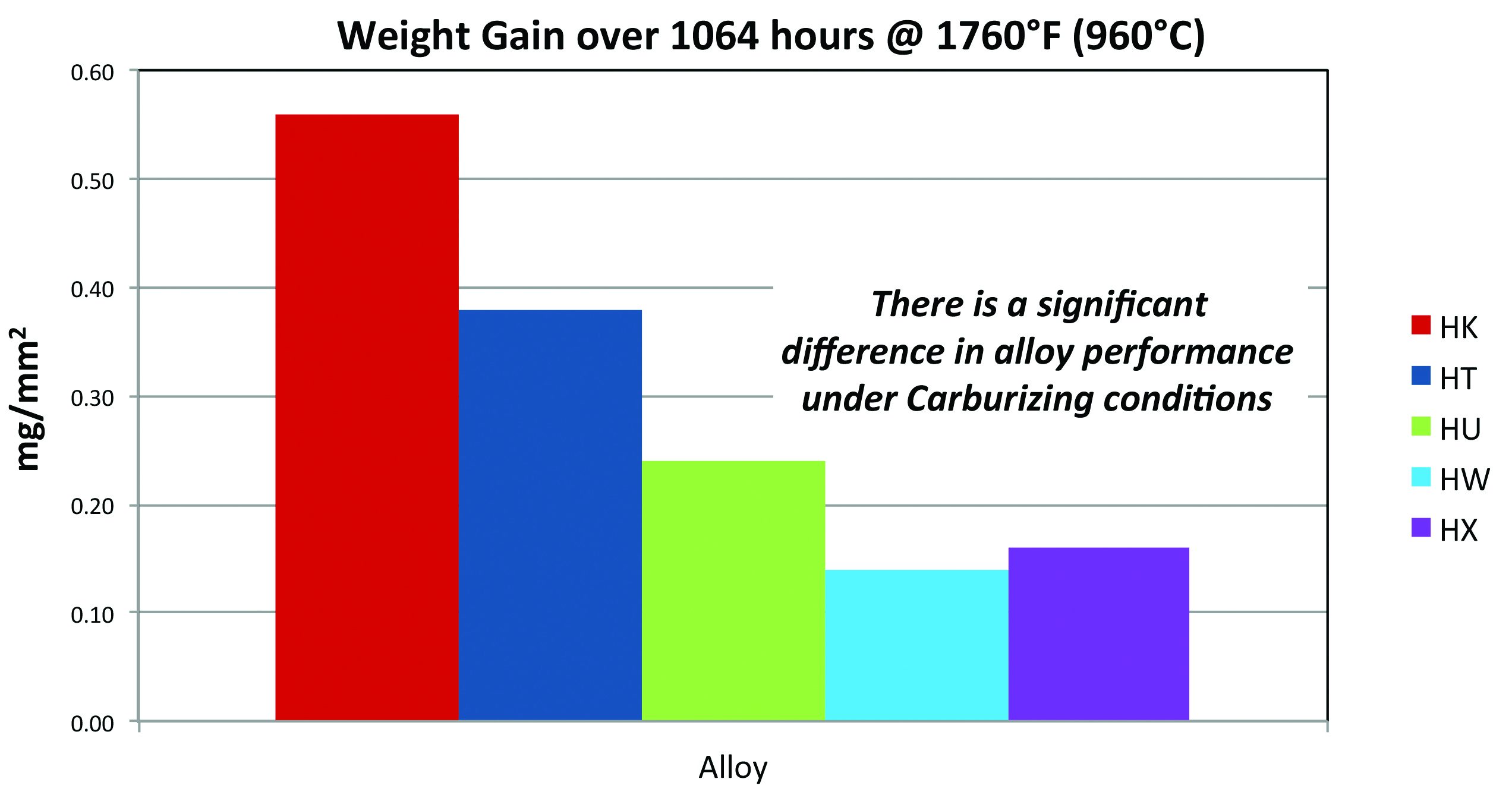
Figure 4 presents the carburization resistance of five common cast alloys: HK, HT, HU, HW and HX. Their performance differs greatly by a factor of four, from best case HW to worst case HK, as indicated by their weight gain over 1,064 hours at1760°F (960°C). Generally the tendency to carburize is decreasing from the left side of graph towards the right as the nickel content of the alloy increases. While the test temperature is reflective of actual carburizing process conditions at many heat treat facilities, keep in mind the radiant tubes actually operate at a significantly higher temperature, and for considerably longer service than 1,064 hours (1½ months).
Excess combustion air as a source of oxidation inside radiant tubes was described earlier. Practically speaking, air also enters the furnace load chamber from a variety of sources including leaky seals or curtains, when the door opens to exchange loads and during weekend burnout of carbon build-up. This chamber-side oxidation also contributes to furnace alloy deterioration. However, Figure 5 shows the Oxidation Resistance of the same five cast alloys differs relatively little as indicated by surface penetration (in mm/year) of air exposure at 1832°F (1000°C).
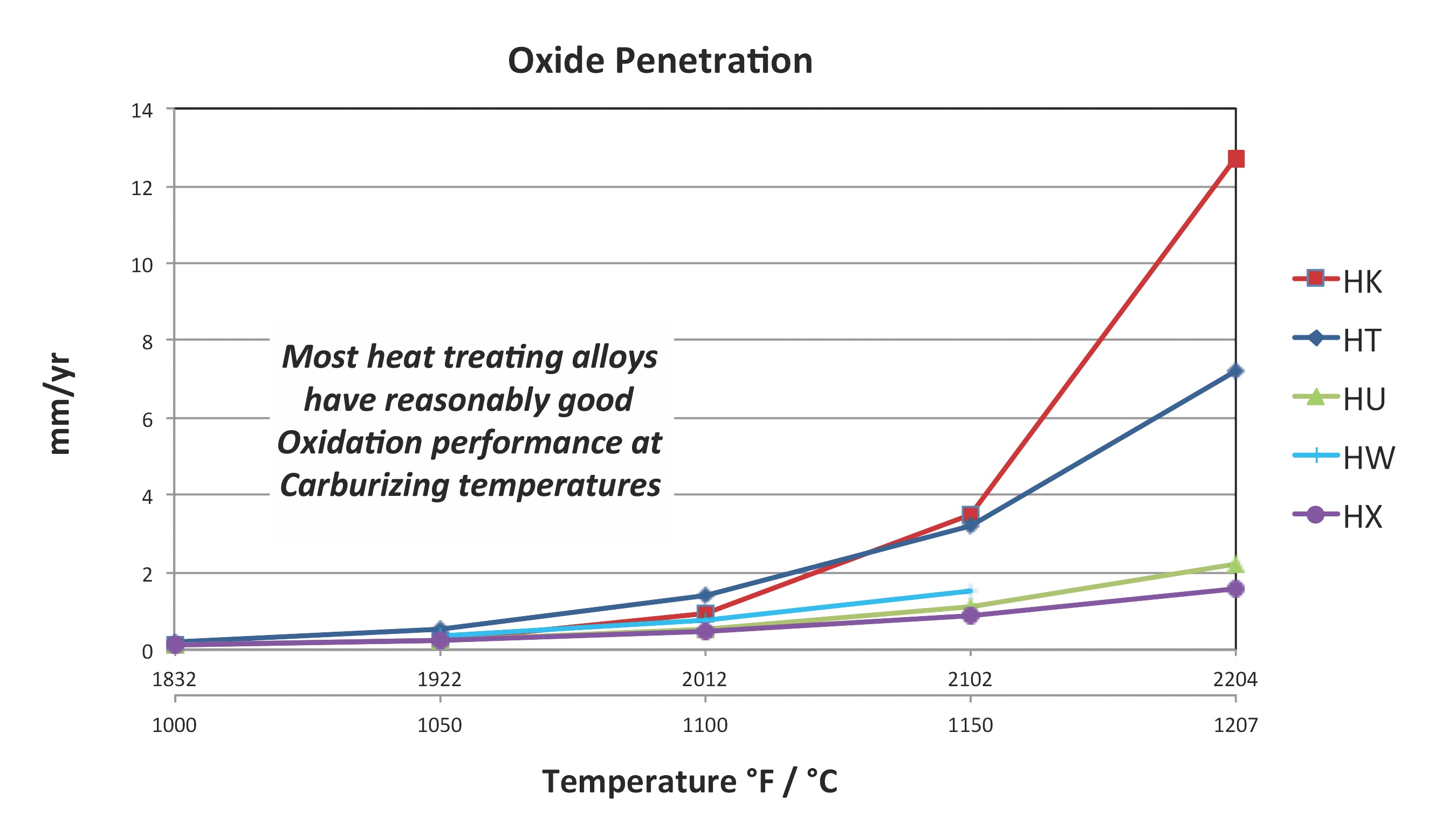
Summarizing recommendations for atmospheric corrosion: 1) Resistance to carburization is a greater factor in metal alloy selection than oxidation. 2) Consider upgrading to HU~333, HW~600 or HX~602 if the increased cost can be justified. However, there is a likely trade-off with Creep Stress performance as shown in the next section. Finally, 3) SiC composites and ceramics are immune to carburization and have excellent creep performance. These should be considered as substitutes for expensive high-nickel content alloys to reduce replacement frequency and life-cycle cost.
Thermo-Mechanical Creep Performance
Figure 6 provides an introduction to creep performance for metal alloys using cast HT as an example. The three dark, dashed curves show the mechanical stress in KPSI (or MPa on the right-hand axis) required to deform an alloy sample 0.01% in one hour, 0.001% in one hour and 0.0001% in one hour as plotted from the top-down respectively. These short-term deformation curves clearly demonstrate how the combination of applied stress and temperature affect the degree of creep. The solid curve is a long-term test showing the stress and temperature required to actually rupture a sample at 10,000 hours (1.14 years of continuous duty). Note how the solid 10,000-hour rupture curve roughly corresponds to the dashed short-term deformation curve for 0.0001% per hour. Rupture occurrence at 10,000 hours X 0.0001%/hr corresponds to about 1% total deformation at catastrophic failure, typical for ductile metals. In heat treating, mechanical stress is supplied by the parts loaded in the tray or fixture, along with weight of the tray, fixture or radiant tube itself. The structural design of the alloy component and its mounting system are also significant factors in the degree of applied stress.
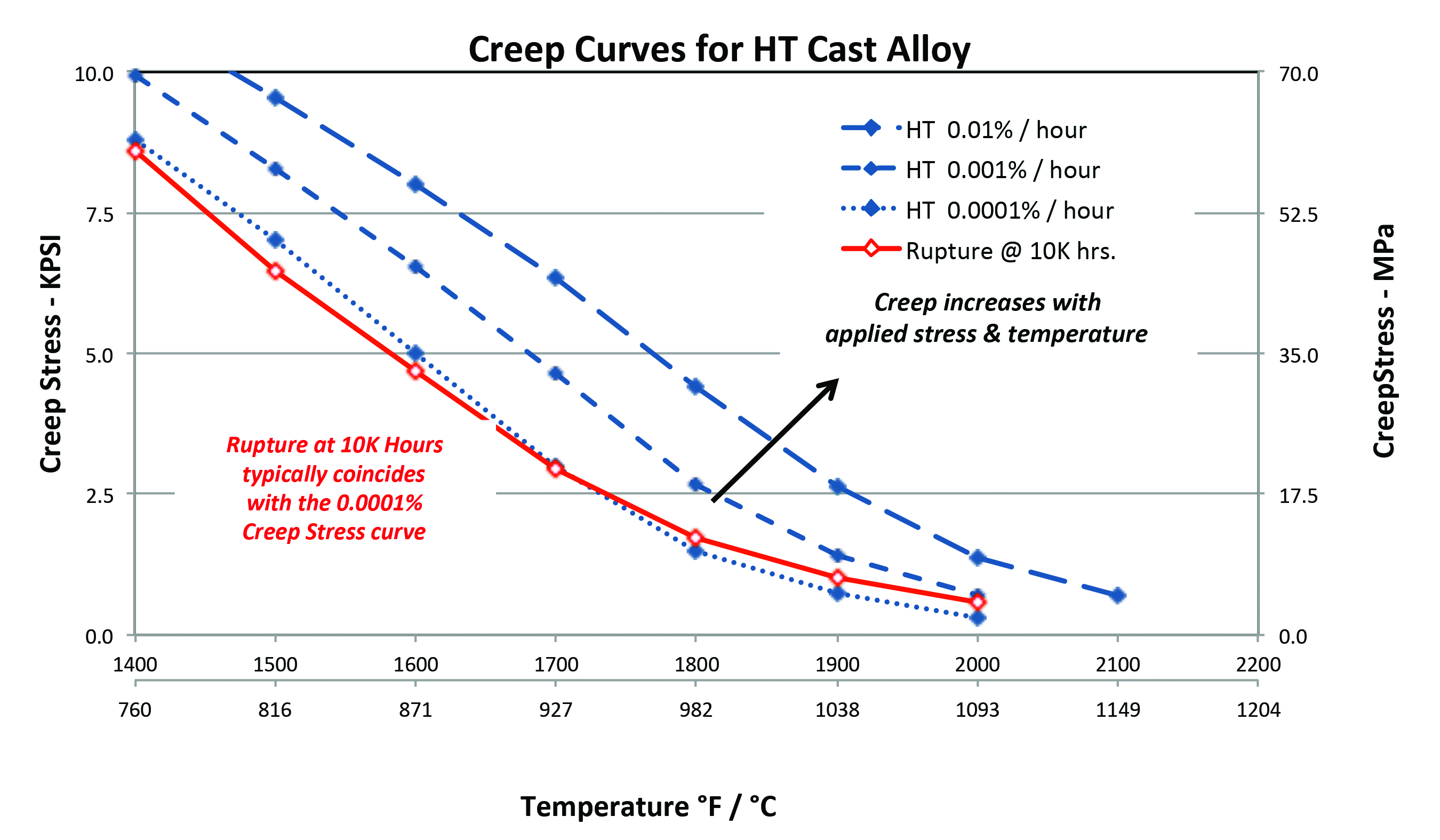
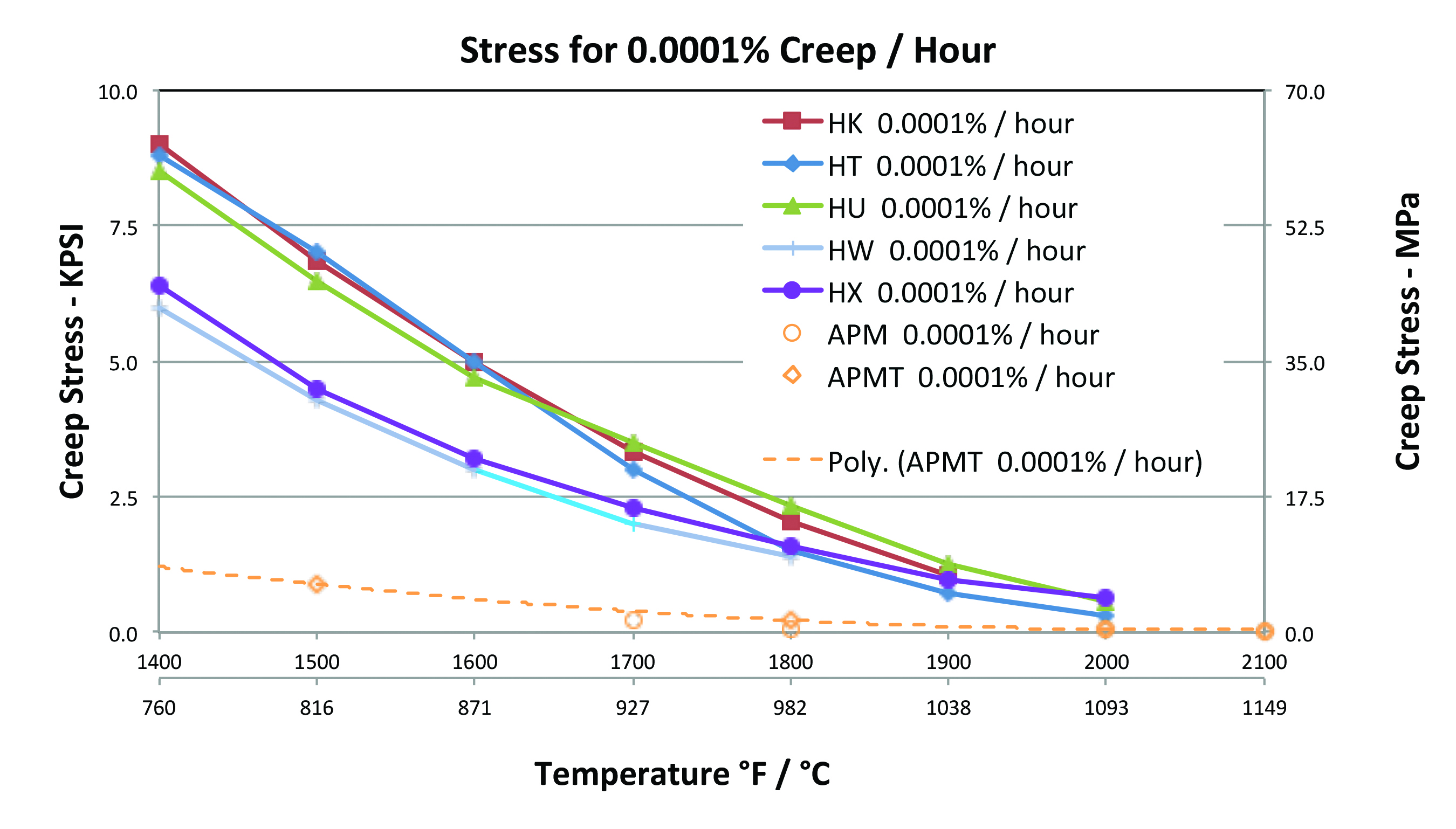
Figure 7 compares the creep performance for the all five cast alloys at 0.0001% per hour. At 1800°F (982°C) and above, HT, HW, and HX all have similarly low resistance to creep, with HW and HX having better carburization performance (per Figure 4). Both HK and HU have somewhat greater resistance to creep stress at 1800°F; however, HK is the most susceptible to carburization. While APM and APMT alloys have excellent high temperature corrosion resistance, their creep performance is relatively poor in this temperature regime. This alloy manufacturer recommends intermediate supports for horizontally-mounted APM and APMT radiant tubes longer than 48 inches (1.2 meters).
An obvious trade-off emerges and we must ask: What is the most critical, life-limiting factor for the specific combination of process conditions and furnace component stresses? To improve life-cycle cost one must evaluate whether embrittlement due to carburization, or deformation/rupture due to creep is the greater problem. Again, keep in mind that the actual surface temperature of radiant tubes is up to 200°F (110° C) hotter than the process setpoint, so they are especially prone to creep failure.
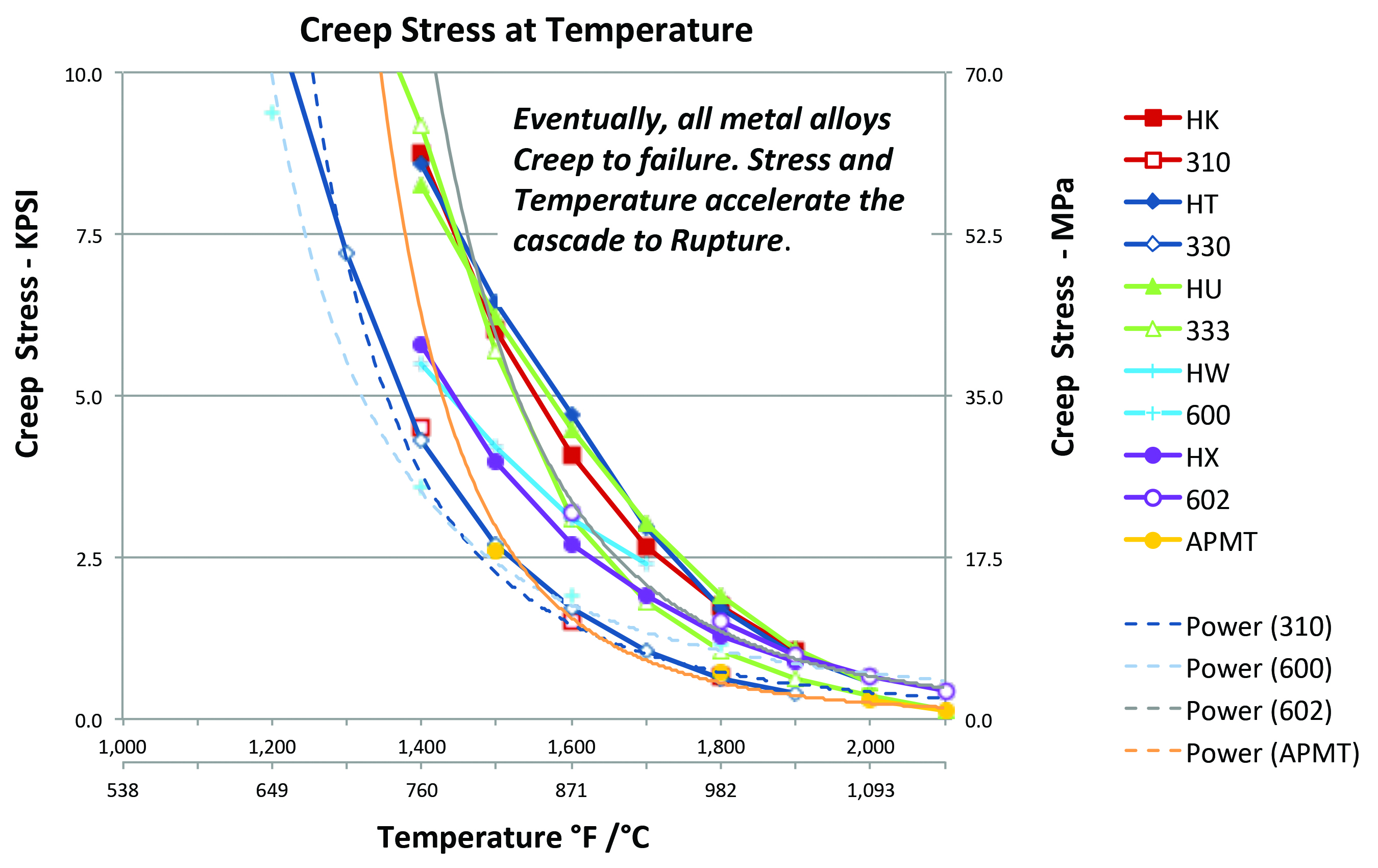
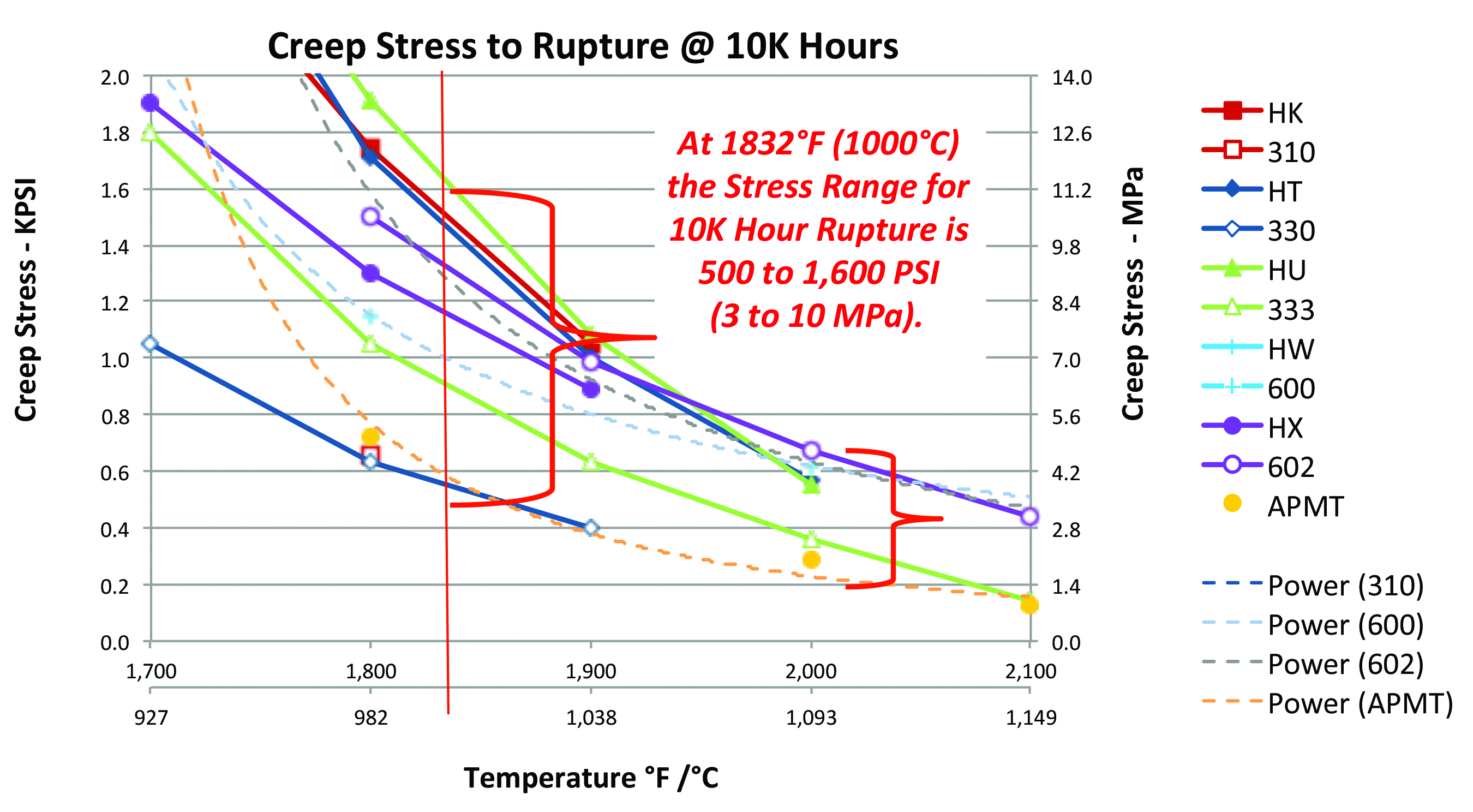
Figure 8 presents alloy creep curves for actual rupture at 10,000 hours (1.14 years). This chart shows that all metal alloys eventually fail above 1800° F (982°C) at relatively low levels of applied stress. Figure 9 enlarges the lower right corner for a more detailed view. At 1832°F (1000°C) the maximum stress at rupture is about 1,600 PSI (11 MPa) for all metal alloys typically used in heat-treating. This is an appropriate temperature for alloy selection when designing trays and fixtures for carburizing service. For radiant tubes operating at 2032°F (1110° C) these same alloys rupture at below 700 PSI (5 MPa). This approaches the stress induced in a metal radiant tube by simply supporting its own weight when horizontally-mounted at each end. Note this is the manufacturer’s data for new alloys as-supplied — not welded, not carburized, and not thermally-cycled.
Figure 10 provides photographic creep evidence from an unconventional perspective comparing Si-SiC composite with high-nickel 600 alloy. The 600 tube at the right is pictured after just one hour at 2462°F (1350° C), while the Si-SiC composite tube on the left is shown after 360 hours under the same conditions. At this extreme temperature no creep deformation, distortion or rupture is observed for the INEX tube.
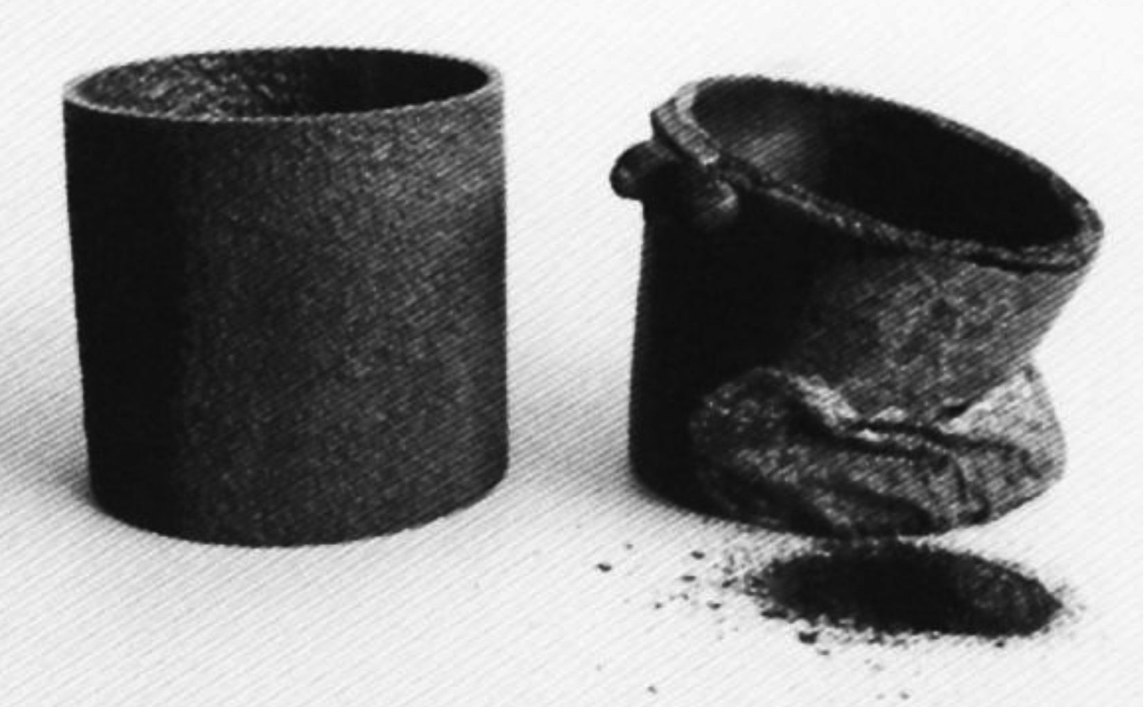
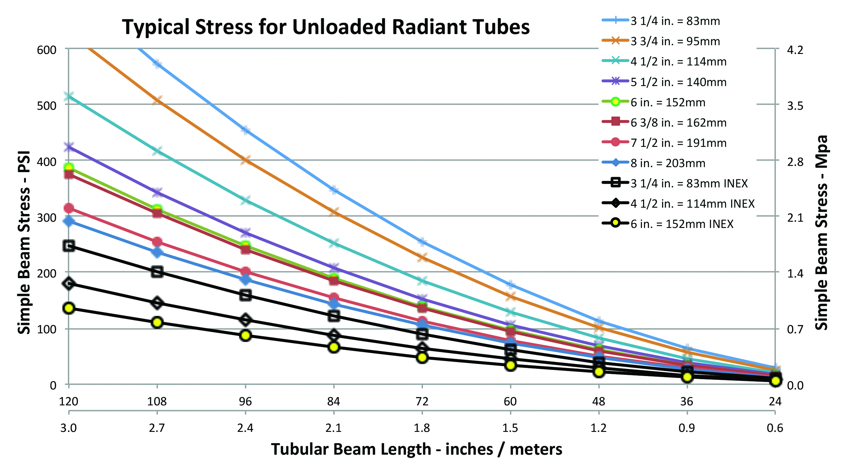
Figure 11 shows the calculated structural stresses for various unloaded, horizontal tubular beams simply supported at both ends. These are induced stress plots for horizontal radiant tubes due to their own weight. The lower black lines are for three standard size Si-SiC composite tubes, which weigh only 1/3 that of comparable metal tubes, and are therefore subject to far less stress. The upper lines are standard alloy tube sizes proceeding top-down from smaller to larger diameter. Tube lengths ranging from 120 to 24 inches (3.0 to 0.6 meters) are shown left to right on the horizontal axis. As expected, the unloaded stress increases with length, and decreases with larger tube OD. At a middle length of 72 inches (1.8 meters) the stresses range from 105 to 255 PSI (0.7 to 1.8 MPa) depending on diameter. This is only one third the tolerable stresses for the new alloys shown in Figure 9— not much of a safety margin against a lifetime subject to the thermal and corrosive severity of carburizing conditions. Sizes for size, Si-SiC composite tubes are subject to much lower stress and have a negligible creep rate.
Summary
Selecting the best alloys for heat-treating trays, fixtures, and radiant tubes is not a straightforward task. While a wide variety of metal alloys are available for carburizing service, each involves a different trade-off between atmospheric corrosion and creep performance. Your choice depends on specific process conditions and which properties are most critical to improving life performance and life cycle cost. Si-SiC composites and slip-cast SiSiC offer excellent performance resisting both corrosion and creep. The trade-off against these advanced ceramic materials is fracture toughness, i.e. susceptibility to mechanical impact. However, when properly installed, Si-SiC composites last indefinitely, usually exceeding the life of the refractory lining, and sometimes outlasting the furnace itself.
Examine the options for your specific process conditions and objectives. Consider the expense of downtime, maintenance labor, and lost production time in addition to the replacement cost of the trays, fixtures, and radiant tubes themselves. Making better material choices improves your process while reducing operational costs and headaches.


 general practice for CQI-9 and AMS2750E")


