


Thermal processing and quenching of steels for hardening is a well-established practice performed by various techniques over the centuries. A common thread has been the unpredictable nature of the size change during the quenching process, which is known as dimensional change or distortion. Material distortion is the undesired trade-off between the development of proper mechanical property and the necessity of rapidly quenching the material from elevated temperatures into a quenching media (i.e. brine, water, polymer, oil, gas, molten salt, etc.). Due to this compromise, users have been attempting to reduce part distortion because, once a component is hardened, it becomes very difficult and costly to remove excess material or form the part back into its original shape.
When one looks at the bearing and gearing industries, materials typically are hardened via austenitizing and quenching. Not only do these components require high hardness and wear/corrosion resistance, they also require high dimensional precision to tight tolerances as well as repeatability of results. One of the most common ways to reduce material distortion when quenching is a method by which a heated component is placed in a special fixture and a steady force is applied to the component. This allows the part to resist material deformation when the quenching media is applied. This method of quenching is known as “press quenching” and requires specialized equipment, manual or robotic handling, custom die sets and high maintenance, as well as being operator dependent to achieve consistent results.
It is well known that machining after heat treatment is one of the most costly and difficult tasks to complete in the entire manufacturing life cycle. This is why an extreme amount of engineering is devoted to the prevention of distortion of a component to ease the post heat-treatment machining operations. With the ever prevailing desire to lower the cost of raw materials and still maintain proper mechanical performance, extreme amounts of pressure are applied to the heat-treatment process to bring up the quality level of the low-cost steel. When using these low-quality steels, they are prone to high levels of distortion during the quenching process, such that they distort more than the allowable amount and either become too challenging to hard machine or are not able to be used all together. Approximately 4 percent of the price of a hardened component is attributed to the removal of post heat-treatment material to so that it meets the finished size requirements. When users can control distortion, they lower the overall cost of the component.
This paper will introduce the latest achievements in the advancement of distortion control by way of 4D high-pressure gas quenching (HPGQ) vs. press quenching. Both processes quench a single part at a time, but the 4D HPGQ process does not subject a part to any clamping forces or issues associated with liquid quenching inconsistencies. The 4D HPGQ process results in every single part being heated and quenched identically the same at surprisingly low gas pressures, thus producing extremely accurate dimensional variation with highly repeatable results. 4D HPGQ systems are easily integrated into current manufacturing environments, and the process is a revolutionary advance in quenching technology, which has been shown to reduce or even eliminate the need for expensive and difficult post hardening
1 Introduction
Quenching of steel for hardening purposes is a metallurgical process that takes place after a material is heated through its phase transformation into the austenitic range and then rapidly cooled, causing the austenite to complete a phase transformation into martensite. During the quenching process, a component experiences a very large temperature gradient throughout its geometry, and if the quench is not uniform, it results in thermal stresses and non-uniform transformation of the microstructure. When quenching is not uniform, the component will experience a large deformation in relation to the pre-heat-treated geometry. To further amplify this phenomenon, a quenching stream that penetrates a batch of parts disperses unevenly, and each part is cooled at a different rate depending on its position in the furnace.
Manufacturers over the years have attempted numerous methods to reduce distortion after quenching, as it is difficult and costly to remove excess material once the component has been hardened. One of the most popular methods of distortion control is the press quench technique, which does not employ batch quenching. Rather, it quenches one part at a time. Press quenching offers very attractive results when it comes to distortion control; however, there are unattractive aspects of the process including safety concerns (handling of hot components), environmental (oil), washing (oil removal), etc., requires special handling and equipment to quench a component after heat treatment.
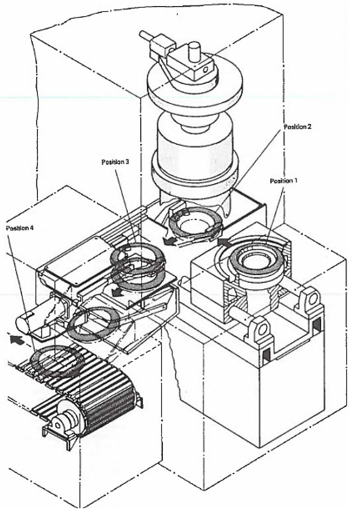
 2 Press Quenching
Press quenching is a process used when batch quenching provides too much distortion where a part’s movement after quench exceeds the additional material left for post heat-treatment removal. These parts consist of case- and through-hardened components (gear, rings, etc.). When components are sensitive to hardening distortion, press quenching offers a versatile way to harden thin cross sections and large geometric parts. They quench one part at a time, providing dimensional stability, controlled distortion, and are very repeatable.
However, press quenching is a special quenching technique designed to control quench process to minimize distortion caused when a part is rapidly quenched after the heating cycle. One of the critical aspects of press quenching is the design and construction of the special dies. These dies are built such that they mechanically align and retain a hot plasticized part with pressure as the die restricts the desired features from distorting when quenching through its phase transformation. Oil flow across the part surface is also important in achieving the desired hardness and microstructure, and as such, the dies must be produced to balance the need for die contact and proper oil flow over the part. Common dimensions that require distortion control are runout, parallelism, concentricity, etc., and when press quenching is done in a proper manner, precise tolerances can be achieved, 0.001” – 0.002” [0.025 – 0.050mm], in relation to the pre heat-treatment dimensions.
3 HPGQ vs. Oil Quenching Power
When discussing quenching, furnace systems will use various quenching processes/media to achieve the desired metallurgical properties. Based on a materials ability — or “in-ability” — to be hardened, more aggressive cooling rates may be needed to reach the required hardness as required for the components end use. The chart in Figure 2 shows the three main types of quenching oil (fast, medium, and slow) in relation to the various quenching gasses (N2, He, H2) used in thermal processing. When we look first at the quench oils, the general quenching capability range across all three oil types is 1,000 – 2,500 α[W/m2K].
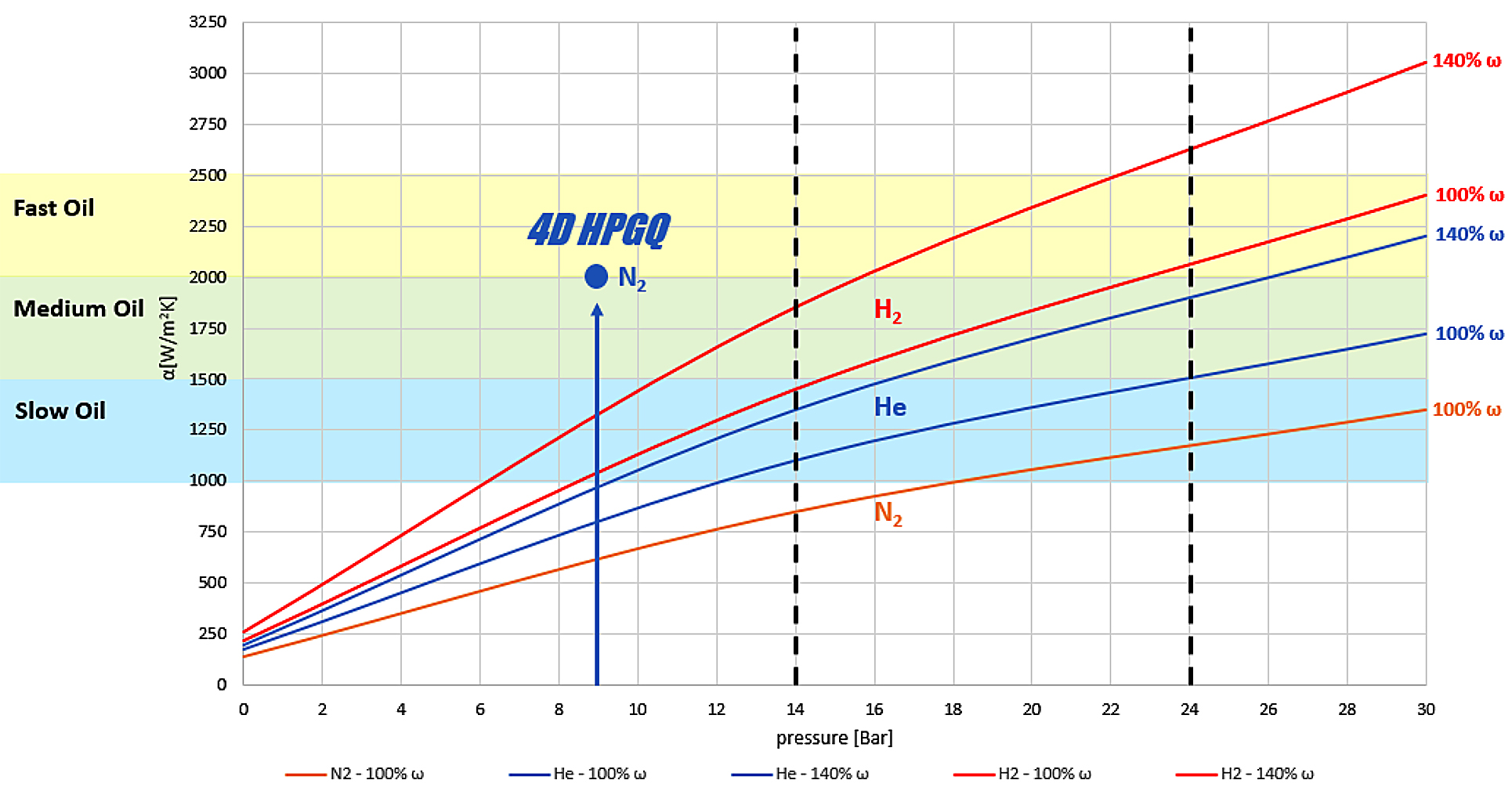
The chart then shows the relationship between the type of gas and how it performs when the pressure increases in the chamber. The vertical dashed lines represent two categories in which vacuum HPGQ furnaces are generally constructed. The dashed line noted at the 14 Bar mark represents a typical single chamber batch HPGQ furnace, and the dashed line noted at the 24 Bar mark is a typical multi-chamber batch HPGQ furnace. Multi-chamber simply means it has a dedicated heating and quenching chamber where the thermally soaked hot zone is not quenched, thus allowing a multi-chamber HPGQ furnace to perform better than that of a single chamber furnace. However, a downside to the multi-chamber batch HPGQ furnace is a more complex and costlier-to-manufacture than that of a Batch HPGQ furnace. When comparing N2 Batch HPGQ vs. Oil, whereas N2 being the most common gas quenching media used for HPGQ quenching, just begins to become as strong as oil when entering the 20-24 Bar ranges. He and H2 round out the other two gasses that both perform better than N2. However, the disadvantages are that He is very costly to purchase and requires expensive reclaiming systems and H2 has its inherent safety regulations and concerns that prevent it from being used in today’s quenching processes. So, where do we go from here? As you can see, 4D HPGQ when only using 9 Bar of N2 quenching gas, has capabilities that fall into the fast-oil quenching range.
4 4D High Pressure Gas Quenching
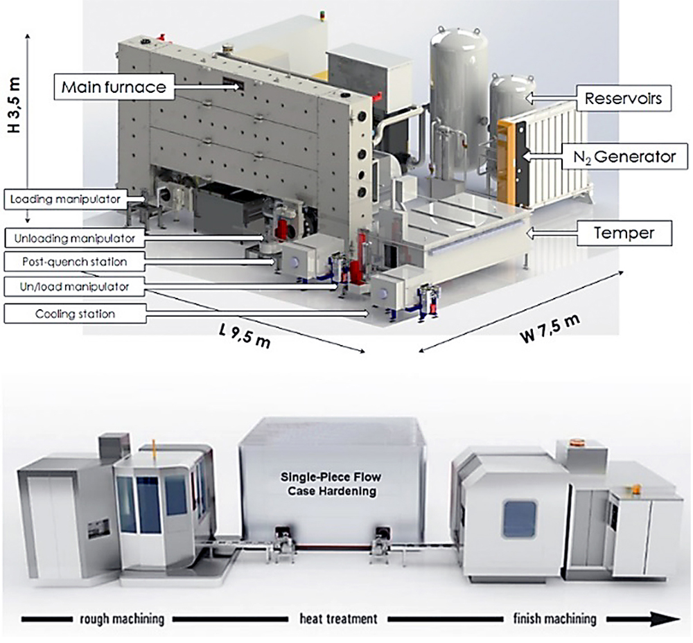
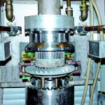
4D HPGQ is a new process that allows for significant improvements to the quenching process with the main focus on reduction of distortion. Distortion reduction is achieved mainly from the use of a high-pressure gas quenching system installed in the quenching/unloading chamber (See Figure 3). The 4D HPGQ quenching platform uses a proprietary cooling manifold and chamber (Figure 4) arrangement that surrounds the part during the quenching process. This approach ensures there is a uniform flow of cooling gas across the part geometry (top, bottom, and side). When talking about top, bottom, and side quenching, this is referred to as “3D” cooling.
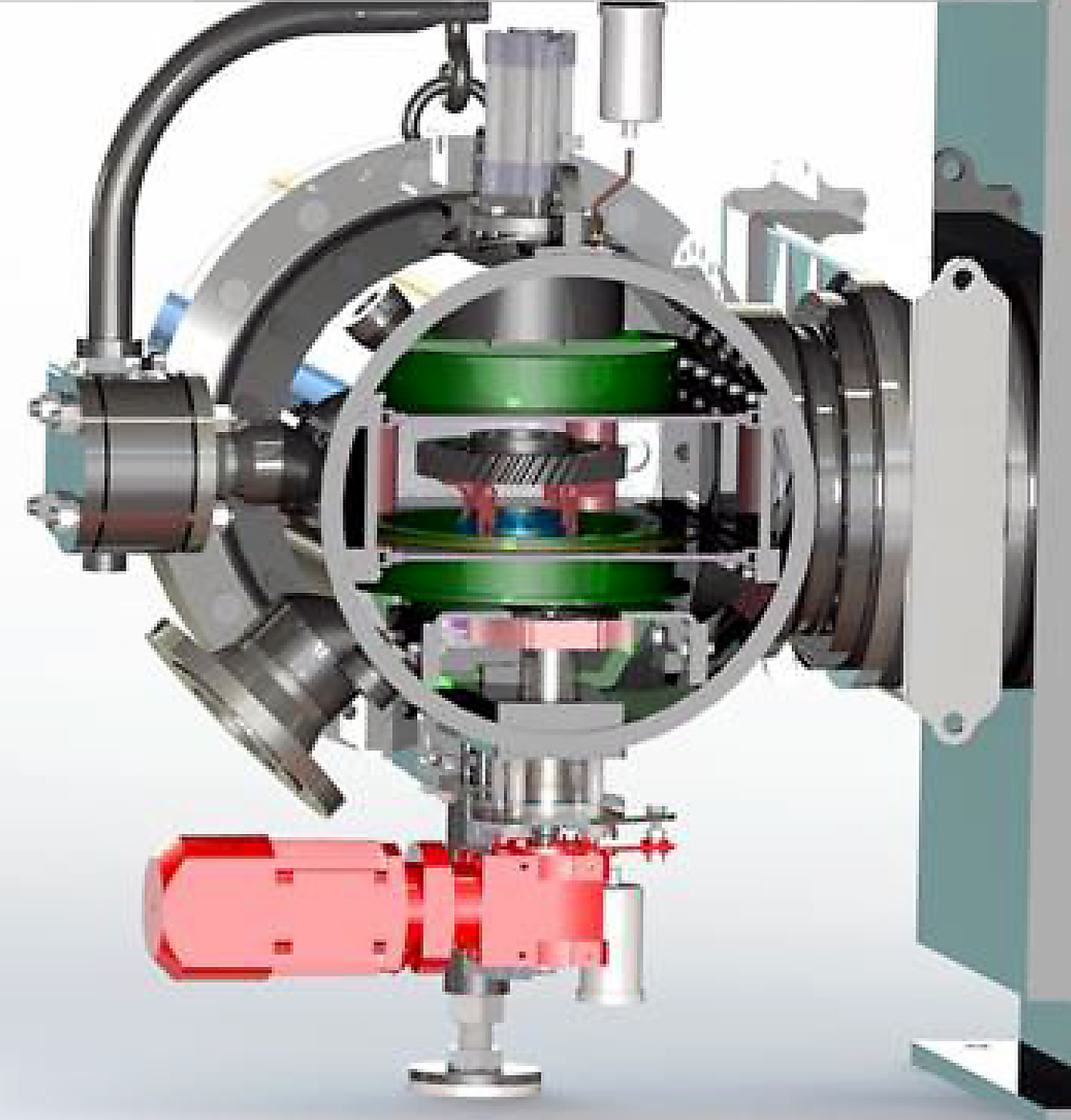
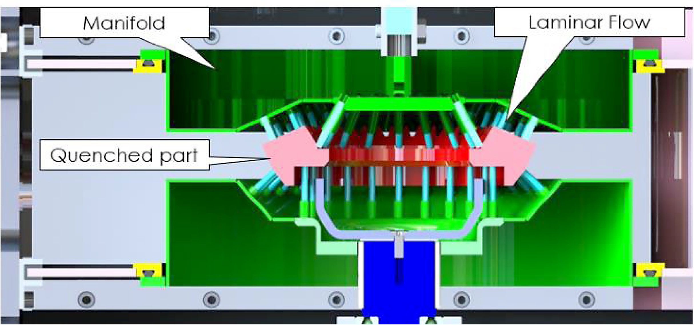
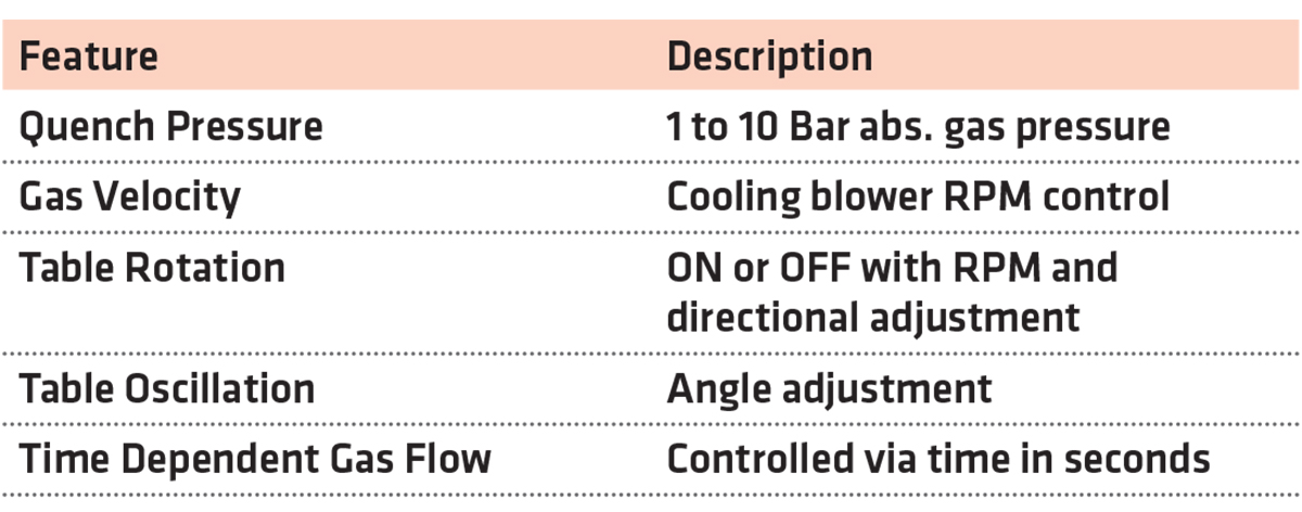
In order to achieve the fourth dimension when quenching, a component is placed in the quenching chamber, the proprietary cooling manifold surrounds the part, and, finally, the support table rotates the component while the N2 cooling gas flows over the part. Tyng both the 3D quenching approach with part rotation, we give birth to 4D quenching, which has the ability to further enhance quench uniformity. With 4D HPQG, it also allows for the best possible quench uniformity to be used. Current 4D quench designs allow for the use of up to 10 bar abs. quenching pressure, where shown previously (Figure 2), 4D HPGQ is now comparable to that of oil quenching without the use of helium. Also, and most importantly, since the cooling nozzles can be adjusted to fit the component’s precise size and geometry, quenching can be fully optimized and distortion significantly reduced.
In addition to the aforementioned features, the parameters in Table 1 are adjustable and can be varied in their combination:
5 Distortion Reduction
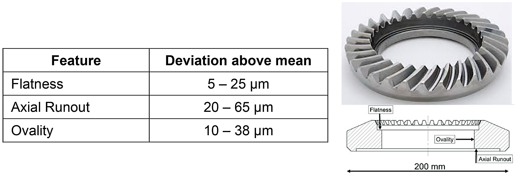
In this section, we will review data from three separate examples. In example #1, the 4D HPGQ process was completed on a series of hypoid ring gears with a 7.9” [200 mm] outside diameter (Figure 5). The requirements were to carburize and quench the gears to obtain an effective case depth of 0.032” [0.8 mm] at 550 HV and tempered at 356°F [180°C].
6 4D HPGQ — Hypoid Ring Gear Distortion Summary
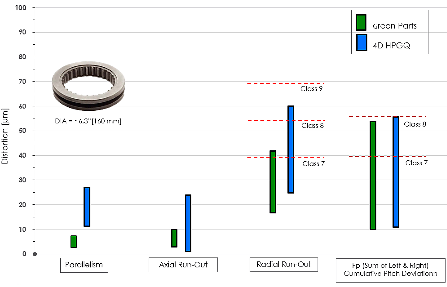
In example #2, the 4D HPGQ process was completed on a ring gear with internal teeth (Figure 6) to compare distortion between pre- and post-heat-treatment conditions. Ring gear dimensions included a 6.3” [160 mm] outside diameter.
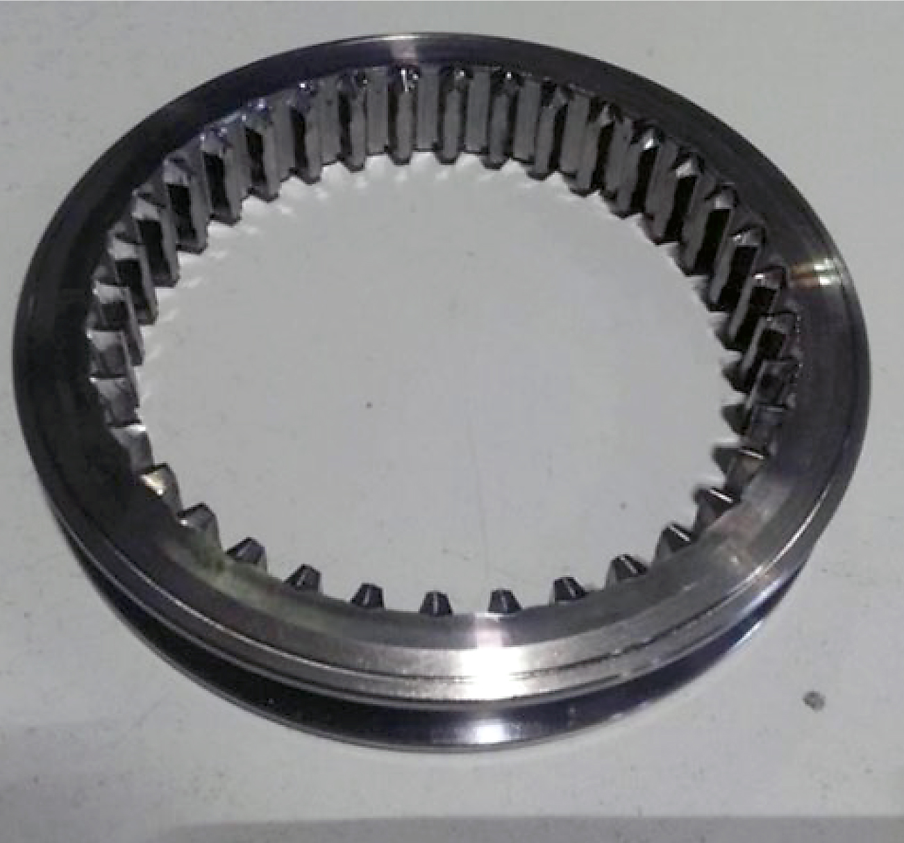
In example #3, the 4D HPGQ process was further improved upon, and tests were conducted on a coupling gear made from 8620 also with a tooth model greater than 3 (Figure 7a). The distortion was compared between pre- and post-heat-treatment conditions. The coupling gear’s dimensions included a 6.0” [152 mm] outside diameter. Associated dimensions measured were radial runout, axial runout, total pitch deviation, total profile deviation, and total helix deviation.
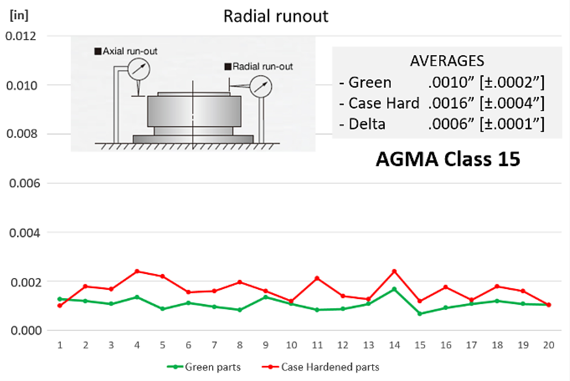
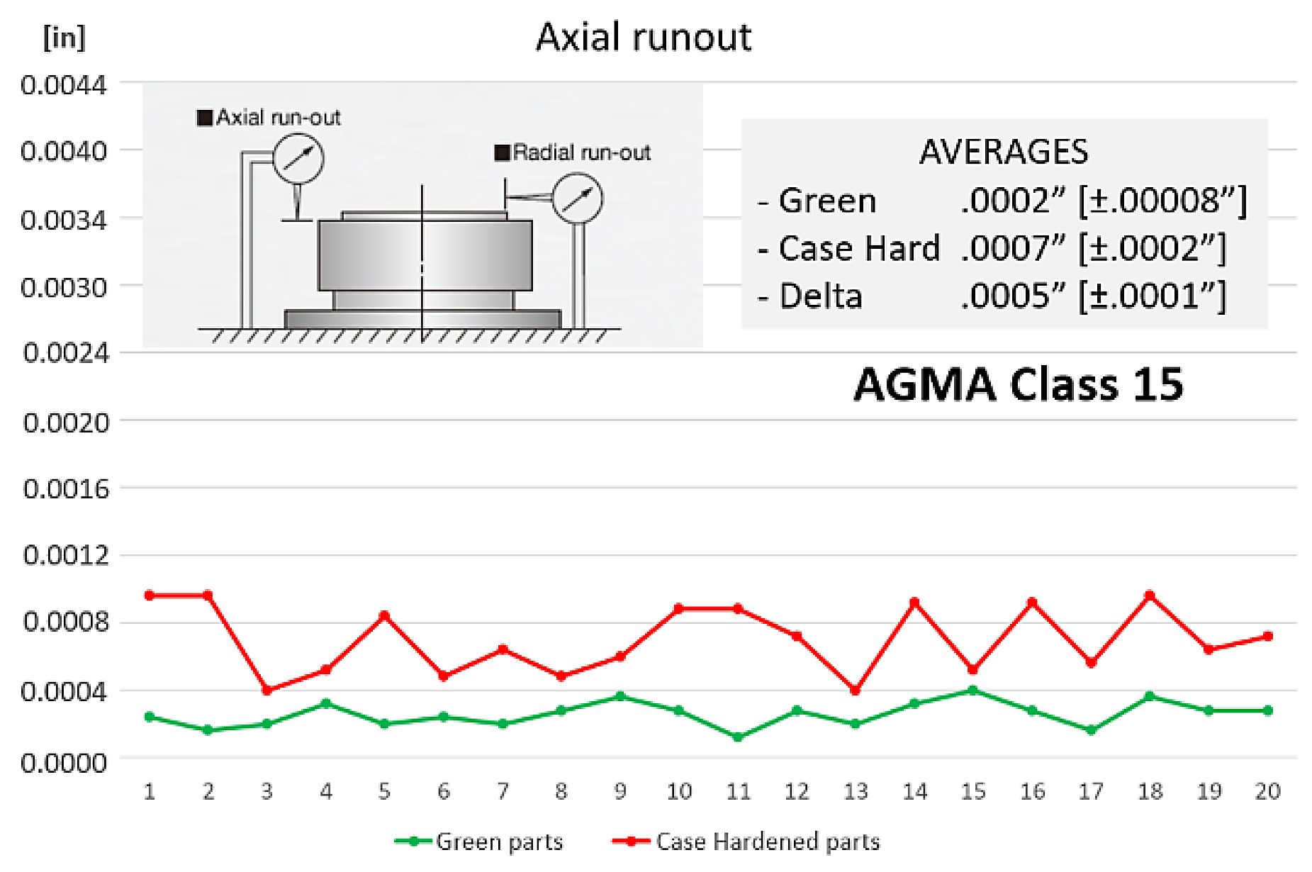
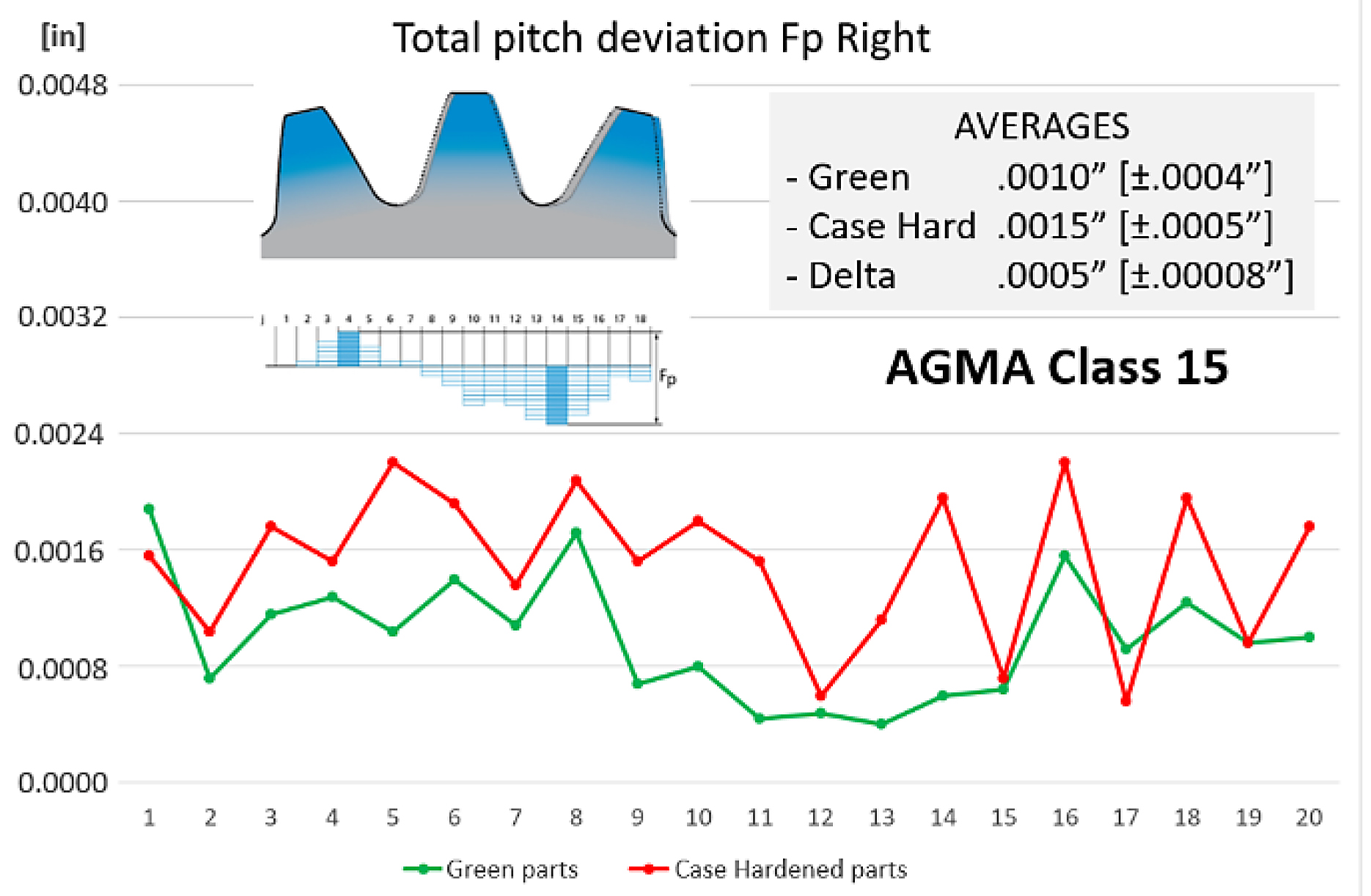
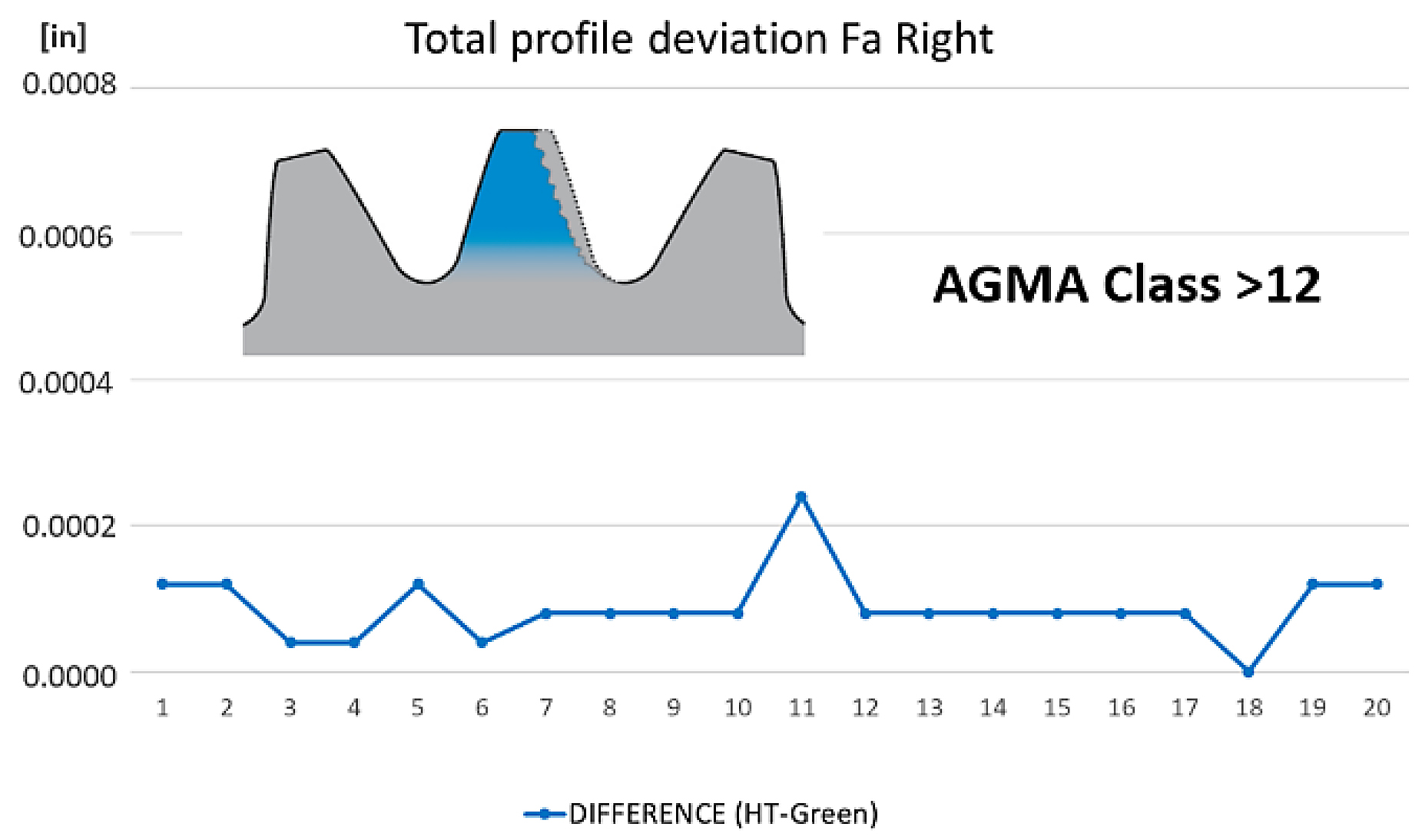
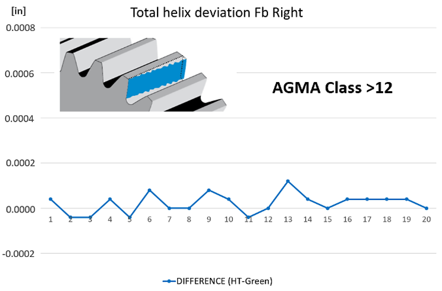
In this trial, it shows that 4D HPGQ can maintain a 12 or higher AGMA gear class quality rating, which is on the same level as press quenching. In general, the 4D HPGQ process proved that it can produce significantly improved distortion results from the hardening process in comparison to its pre-heat-treatment features. Comparatively speaking, the UCM, when configured to its optimum quenching capacity, can provide five times the improvement in distortion to that of batch oil quenching. When distortion is reduced, it flows downstream to the subsequent machining operations, whereas machining and grinding steps can be reduced and/or even eliminated altogether.
7 Conclusion
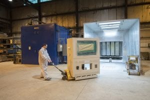
Costs of post-heat-treatment material removal are significant to the overall cost of a finished component from costly machines, special tooling, and skilled labor. It is been estimated that in the mid-1990s that in the automotive industry alone, approximately $22.4 billion [2] was spent on the correction of distortion of hardened components. 4D HPGQ is a new process that gives end users a tool to, not only reduce the distortion of a quenched component, but they can fully optimize the quench process due to the systems flexibility and customization. In addition to the distortion benefits, the system is environmentally friendly, safe to operate, and can be implemented into a machining work cell (See Figure 8). When a 4D HPGQ is implemented in a machining work cell, it can eliminate the need for costly fixturing and material handling expenses associated with batch- and press-quenching platforms.
The weaknesses that come from traditional quenching platforms cannot be overcome. If more improvement is required in terms of precision and repeatability, a new tool can be used to control the process, reduce distortion, and even integrate the in-line to a production setting. This is the first and only way the real single-piece flow heat treatment with 4D quenching can be implemented, which will guarantee ideally the same process parameters for every single part in a series.
Acknowledgments
Research and publications were supported by the National Centre for Research and Development as part of project no. POIR.04.01.04-00-0087/15 entitled: “Equipment for high performance and precise heat treatment with a quenching deformation reduction system for direct application in downstream production chains of mechanical gearing and bearings.”
Bibliography
- 1991, ASM Handbook, Volume 4, Heat Treating, ASM International, Quenching of Steel, p. 108.
- Bremen, 1995, “Economic consequences of distortion.” IWT (Institut fur Werkstofftechnic), Germany.
Printed with permission of the copyright holder, the American Gear Manufacturers Association, 1001 N. Fairfax Street, Suite 500, Alexandria, Virginia 22314. Statements presented in this paper are those of the authors and may not represent the position or opinion of the American Gear Manufacturers Association. (AGMA) This paper was presented October 2019 at the AGMA Fall Technical Meeting in Detroit, Michigan. 19FTM14


 general practice for CQI-9 and AMS2750E")


