


The various forms and fixtures used in vacuum furnaces and various sintering operations nearly all require graphite. Machining some of these graphite components can present challenges. Two of the most common challenges are:
Furnace components: Heating elements and measuring electrical resistivity.
Sintering process: Eutectic melting issues.
First, let’s discuss vacuum furnaces and the purpose of graphite components and graphite tooling.
A vacuum furnace is a type of furnace that can heat materials to very high temperatures. The controlled heating function is designed to carry out metallurgical processes such as heat treatment, sintering, or brazing.
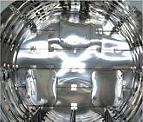
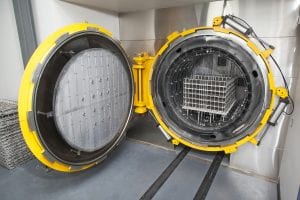
The area where the process heat is produced is called the hot zone. Since the early development of the vacuum furnace, engineers and thermal experts have tried to improve the insulating characteristics and the performance of the components inside the hot zone. Many of the early designs of vacuum furnaces used an all-metal design (Figure 1). The entire hot zone is manufactured completely out of metal components.
As vacuum furnaces became an important production tool, engineers have tried, with varying levels of success, to incorporate alternate materials into designs for vacuum furnaces.
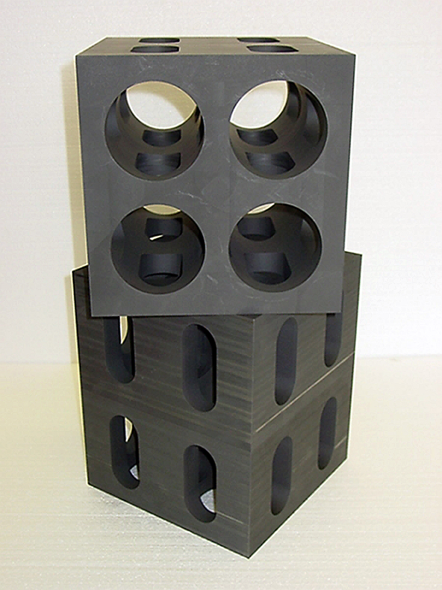
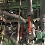
One of the most common types of hot zones manufactured today uses graphitic materials in the form of sheets, felt, or board for insulating purposes. These hot zones also use synthetic graphite components such as heating elements, connectors, and furnace bases. In addition, various tooling used to support or locate material inside the furnace is composed of synthetic graphite. The multitude of acceptable graphite grades that is available, along with many available graphitic insulating components, offers the end user a wide selection of advanced materials options to choose from. Synthetic graphite also allows for complex machining, allowing for intricate designs to be produced relatively fast, and cost effective (Figure 2).
Choosing the correct material
It is very important that with each particular application, the appropriate material is used. Choosing the correct materials characteristics and purity levels will ensure that vacuum furnaces, some of which are capable of running at uniform temperatures up to 5,250°F, can control and maintain an atmosphere with low contamination and minimal power losses.
As graphite has emerged over the past few decades as a highly engineered material, its use in manufacturing hot zone components increased. Vacuum furnace manufacturers, using graphite, were able to change the shapes, and reduce the size and weight of the hot-zone components to increase efficiency. They also incorporated graphite hot-zone components to facilitate intricate part designs that can be manufactured quickly and reliably. Modern purification processes allow for very high purity levels to be achieved with graphite. Synthetic graphite typically has a purity level of 300-500 ppm, but with additional post-production purification, it is possible to reach levels of 0.05 ppm or less. (Furnace fixture engineered with reduced mass to obtain reduced ramp rates and quench rates.)
Measuring electrical resistance
The heating element is a critical component in graphite hot zones. One challenge that has arisen in the production of graphite heating elements is the proper measurement of electrical resistance. The graphite heating element’s purpose is to get hot, reliably and consistently, from element to element.
When designing the manufacturing process for heating elements, one has to think about electrical resistance. In the case of most other graphite components, a print and a material spec sheet would suffice in order to produce the components. That is not sufficient when designing and machining heating elements. Clearly defining the electrical resistance, along with clear designation on how and where the resistance is to be measured, is critical for the efficiency of the hot zone. It is important to understand, though, that electrical resistance can vary between blocks of the same grade of graphite as well as within a single block of graphite. Using highly engineered synthetic graphite from world-class manufacturers does help with reducing variability in electrical resistance, but it doesn’t transform this quality into a constant. Proper measuring and resistance testing of each arc element is the only way to ensure the vacuum furnace hot zone will produce constant temperatures and run efficiently.
The availability of multiple quality graphite grades is a benefit, but it can also pose a challenge as every grade has a different electrical resistance. It is important to note that an arc element’s basic dimensions do affect its final electrical resistance, so setting the final electrical resistance as the mandatory requirement and allowing the part geometry to vary is good practice.
Thinner components have an increased resistivity compared to thicker ones. And then there is the consideration of the best location to measure resistance. Measure in one location and the values are totally different than if the measurement is taken in a different location. Measuring electrical resistance, it turns out, is quite complicated, and the sum of all these variables can pose a challenge for the uninitiated. Graphite component manufacturers need to have a good understanding of all these factors. They must choose the right materials and understand how resistance changes as dimensions change.
It is important for both the customer and vendor to clearly define how and where the target resistance is measured. Defining these parameters is critical to producing an element that will work properly. The burden is on the vendor to not only provide a quality product, but also to educate customers so they can make informed decisions.
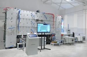
This video shows resistance testing of a graphite arc element at various locations and the corresponding change in measured electrical resistivity: tinyurl.com/semco-carbon.
Eutectic melting
Another common issue encountered in heat treating metal components is eutectic melting and the role of graphite fixtures in the sintering process. Eutectic melting is the process in which an alloy of two or more metals, when heated, completely changes from solid to liquid at the same temperature. There are processes, such as brazing, where eutectic melting is a desired result. In fact, there are thousands of eutectic compositions used in brazing applications. They play a major role when heating a brazing filler metal up to the brazing temperature, as well as when cooling after brazing. During heat-up and melting, the eutectic composition will be the first to melt, and because of its narrow melting range (solids and liquids are at the same temperature), the eutectic composition will flow into the braze joint.
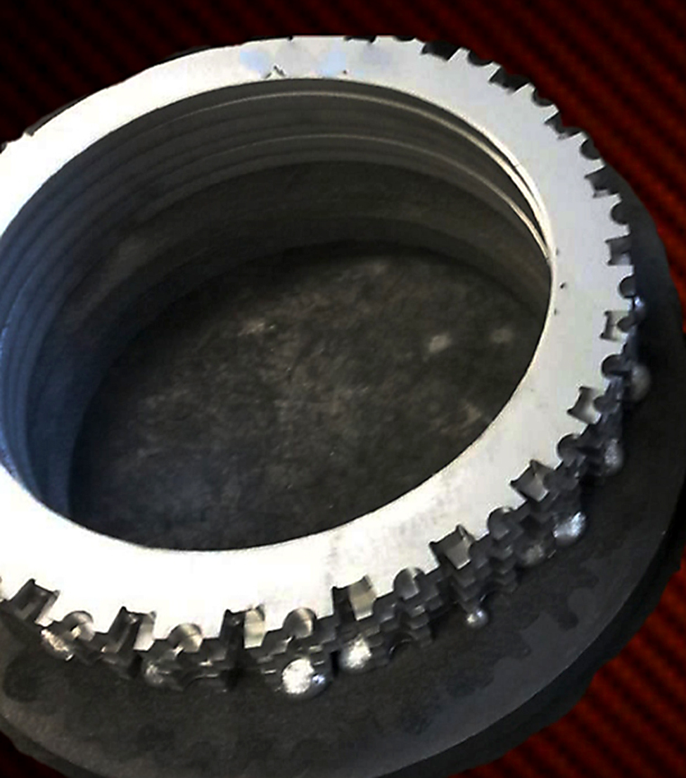
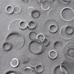
While eutectic melting is sometimes preferred, there are also industrial processes where the eutectic melt is not a desired effect and can actually cause major issues within the process. A bonding effect can occur between various graphite fixtures and the processed materials. Heat-treat processes using graphite fixtures are susceptible to eutectic bonding. The cause of this susceptibility is the interaction between certain elements through solid-state diffusion. When graphite fixtures are present, carbon atoms can transfer from the graphite fixtures to the metal to be treated. This transfer can change the melting point of the metal and create fusion between the working surfaces or even the complete melting of the metal. The near-perfect surfaces on both the metal (especially oxide-free metal surfaces) and the graphite fixtures can contribute to this diffusion (Figure 3).
Eutectic bonding can occur in sintering as well as in vacuum processing with adverse results. In these processes, major consideration should be given to selecting the graphite fixture material and designing the synthetic graphite fixturing that best reduces surface contact.
Solid state diffusion of certain elements can cause the formation of an undesirable lower melting point alloy (eutectic). For example, solid-state diffusion between carbon and nickel can begin to occur at temperatures as low as 1,165°C (2,130°F) and cause local melting and bonding. Under the proper conditions, molybdenum will also combine with other elements to cause eutectic bonding. However, the molybdenum reactions with common elements in steel tend to occur at temperatures well above the normal heat-treating range.
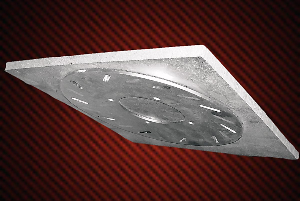
The process of selecting the proper graphite fixture material is not to be underestimated. Severe eutectic bonding reactions can cause extensive damage to workloads. The cost to repair this kind of damage can reach into the tens of thousands of dollars. In the worst cases, entire hot zones need to be rebuilt. In Figure 4, an entire set of graphite fixtures, and the associated stainless-steel parts to be heat-treated, ended up being scrapped. The bonding process was so severe that the graphite plates and stainless-steel parts warped, making them unusable.
Sometimes the easiest solution is the best. Modifying the treat temperature by as little at 5 to 10 degrees F up or down can inhibit the eutectic ally from binding, or from being created altogether, if that is not the purpose of the treat. If the process does not allow modifying the treat temperatures, alternate solutions consist of creating barriers between the potentially reactive materials with non-reactive materials (insulators). These insulators are often available in the form of papers, graphite foils, or other solid shapes upon which the work pieces can be placed. Additionally, coatings of high-purity ceramic materials such as aluminum oxide can be used. These are available in the form of paints and sprays to be applied to the surfaces in contact.
To avoid any undesired effects of the heat-treat processes, consider all these scenarios and be sure to take the precautions recommended.


 general practice for CQI-9 and AMS2750E")


