


Gravity is a nonuniform stress that influences sintering densification, microstructure evolution, final properties, and dimensional uniformity. An early conjecture was that in the absence of gravity, more uniform sintering would be possible. That conjecture proved wrong. The removal of pore buoyancy, grain compression, and substrate friction results in less sintering densification and more distortion. We are finally sensing the large sintering trajectory difference associated with different gravity environments. Toward this end, parallel microgravity and ground sintering experiments are in progress. Samples in these studies are characterized for density, distortion, segregation, and microstructure. Included in the study are computer simulations of the furnace operation, sample densification, and distortion. Extraterrestrial sintering is in progress, offering time resolved densification and distortion data. Variations in sample composition allow extraction of constitutive models needed to map the sintering response with and without gravity. Such models enable predictions relevant to space-based repair and additive manufacturing. Much effort is required to ensure the experiments are safe as they are being conducted on the International Space Station, a manned habitat.
Introduction
Extreme care is needed to ensure safety for manned extraterrestrial experiments. To that end, assessments are performed for vibration, leakage, vapor containment, toxicity, and other concerns using ground-based trials. These are performed by the National Aeronautics and Space Administration (NASA). Access to the International Space Station (ISS) is granted on a competitive basis guided by periodic NASA Research Announcements (NRA). In our case, years passed from our proposal to flight on the SpaceX CRS-14 (Commercial Resupply Service), which launched April 2, 2018.
The science is carefully assessed by independent researchers (Science Concept Review or SCR) and the hardware and assembly procedures must pass careful engineering review. These steps are over. The Low Gradient Furnace (LGF) is provided by the European Space Agency (ESA). It is located in the Materials Science Laboratory (MSL) Materials Science Research Rack (MSRR). The 12 mm diameter by 12 mm high samples are loosely packaged in 15 mm inner diameter alumina crucibles in evacuated Sample Cartridge Assembly (SCA) tubes. Science Reference Module (SRM) ground-based proof experiments are processed at the Marshall Space Flight Center (MSFC) in the Multi Use Ground Sample (MUGS) program. Trial data from Thermal Qualification Tests (TQT), and Ground Flight Tests, such as G2, are applied to make Transient Thermal Predictions (TTP) to assess actual thermal profile versus Set Point (SP) with adjustments via the Adiabatic Zone (AZ) temperature. Note that extraterrestrial research mandates learning a language of acronyms.
Prior Studies
Up to now almost all sintering was performed with gravity acting to compress the grains and make contact with the substrate. For massive components, we long ago recognized gravity induced anisotropic dimensional change. Indeed, gravity is simply an accepted part of sintering.
Formal studies on anisotropic sintering response started with Lenel and co-workers [1,2] using copper compacts heated in different support orientations. Waff [3] found gradients in liquid phase sintered geological structures, including differences in crystal grain size. Subsequently, Niemi and Courtney [4] studied the gravity role in liquid phase sintering (LPS) Fe-Cu alloys with a focus on gravity induced solid-liquid segregation. In a novel variant, Fang et al. [5] relied on a neutral buoyancy system for 1g LPS coarsening experiments.
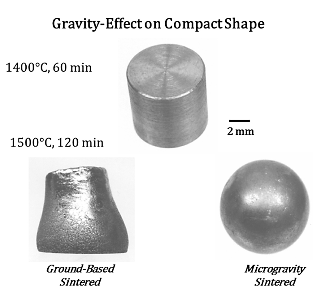
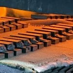
Sounding rocket trials provided first results on liquid phase sintering for 12 to 60 seconds without gravity [6]. Unfortunately, gravity effects take longer, as demonstrated by Kipphut et al. [7], Liuet al. [8], and Lame [9]. Data from microgravity sintering show a different trajectory; microgravity sintering gives incomplete densification, coalesced large residual pores, and large distortion [10-14]. An example of the sintering trajectory difference is captured in Figure 1. This image compares the pre-sintered compact (top center) with the shape after sintering at 1,500°C for 120 minutes in ground (lower left) and microgravity (lower right) conditions for 83W-12Ni-5Fe. The microgravity sample was less dense and more distorted.
With the advent of powder injection molding and additive manufacturing, anisotropic dimensional change from gravity is a problem [15,16]. Accordingly, new models arise with added gravity features [17-19]. These models are awaiting trial data from the current experiments. One long-range prospect is to use extraterrestrial additive manufacturing to construct Martian or lunar habitats. Also, additive manufacturing is anticipated for space-based repairs. These options beg the question on how to accommodate different gravitational situations, including microgravity (µg).
Earth-based sintering (1g) shows densification prior to distortion. Thus, short sintering holds are beneficial to dimensional control. Sintering in reduced gravity leads to incomplete densification since there is an absence of pore buoyancy and grain compression, while there is more distortion due to the missing stress on particle-particle contacts. If extraterrestrial habitats are to be constructed by advanced robotic factories, then problems will occur since we are unable to anticipate size, shape, density, properties, or defects when sintering in space or on the moon or Mars. These points justified the current experimental program, known as Gravitational Effects on Distortion in Sintering (GEDS). The critical questions are as follows:
1. How does gravity influence sintering densification and distortion?
2. Can this behavior be predicted?
3. How will this be included in computer simulations?
4. Will it be possible to conduct meaningful extraterrestrial sintering?
Sintering on ISS
The start of this program came with the 2010 NRA and a formal bid for experiments aboard the ISS. Two years after selection, a science panel was assembled to review laboratory data in a science concept review (SCR). The research idea passed into flight qualification mode in late 2012. Subsequently, interface with the LGF required design of SCA tubes containing the samples. Several issues were addressed and difficulties overcome to allow flight hardware launch in April 2018.
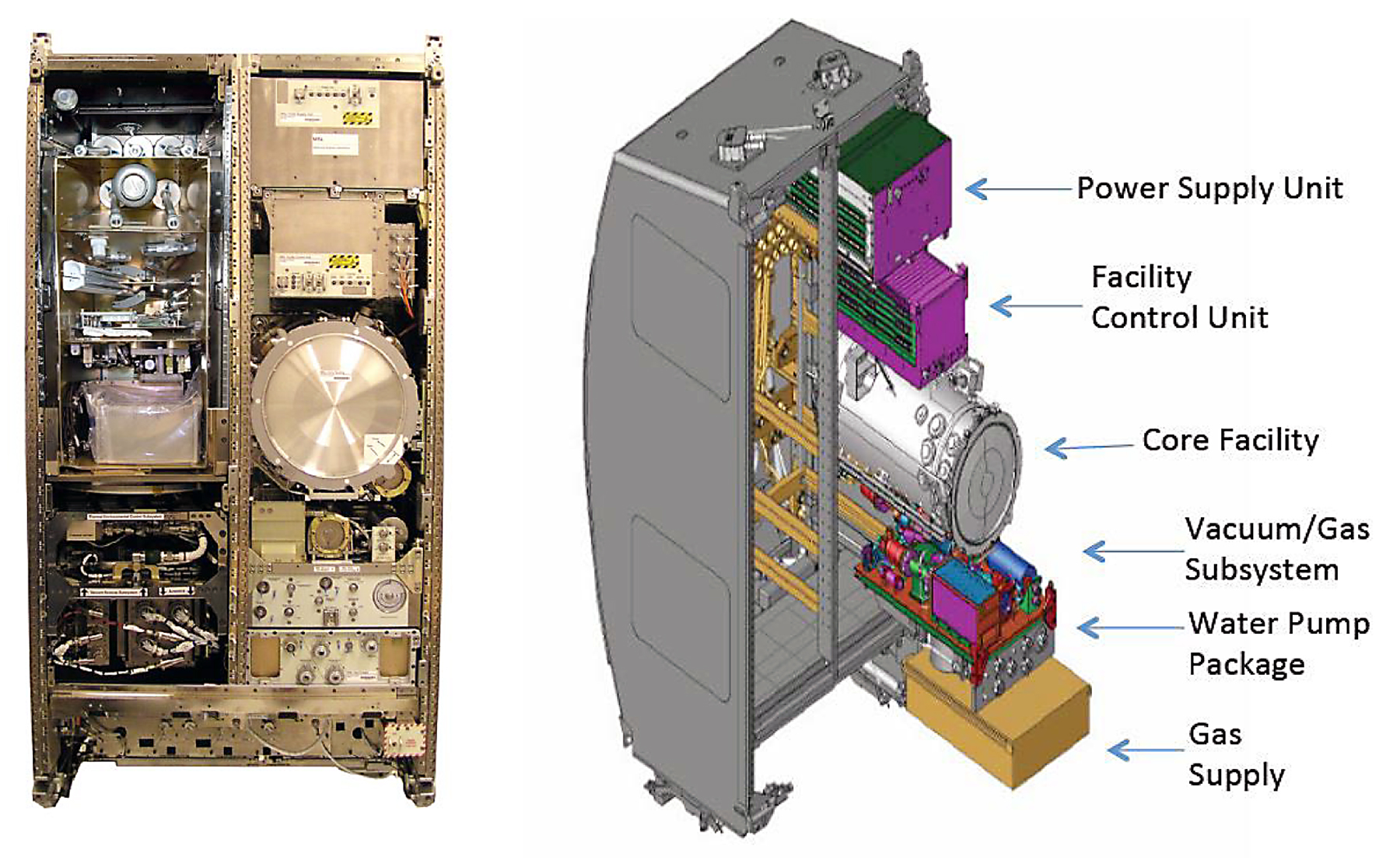
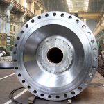
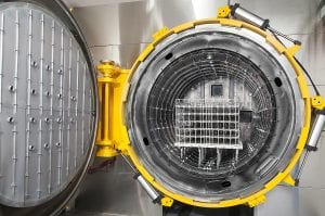
The ESA provided LGF is pictured in Figure 2. It consists of a core furnace with vacuum, power, and support units for water and process gas. The left is a photograph and the right is a layout schematic. Vacuum-sealed SCA tubes containing the samples are inserted in the furnace for each run. The bore is 30 mm with 250 mm heated length; the 30 mm diameter limits sample size, the flight samples are 12 mm diameter. The furnace maximum temperature of 1,200°C as set by thermocouple life. This limitation mandated the search for a tungsten alloy that densifies at 1,200°C. The LGF has temperature stability and uniformity rated at ± 0.5°C.
Samples
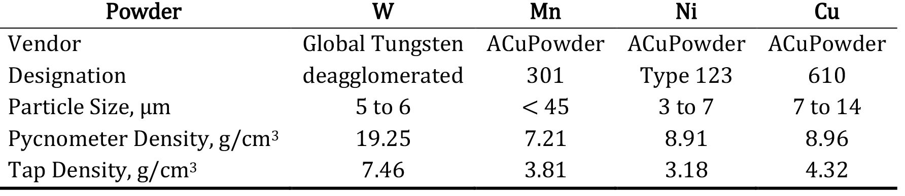
The development of a W-Ni-Cu-Mn heavy alloy for low temperature liquid phase sintering is detailed in prior publications [20,21]. This alloy is compatible with the furnace temperature capability. The density difference between solid (19.2 g/cm3), liquid (10 g/cm3), and porosity (0 g/cm3) accentuates the role of gravity in small samples. Commercial tungsten, nickel, copper, and manganese powders were used as identified in Table 1.
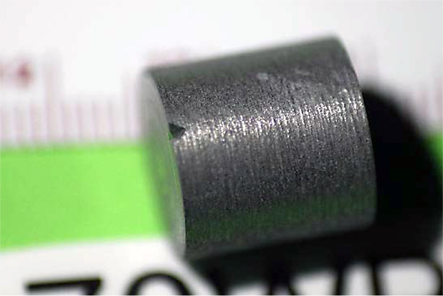
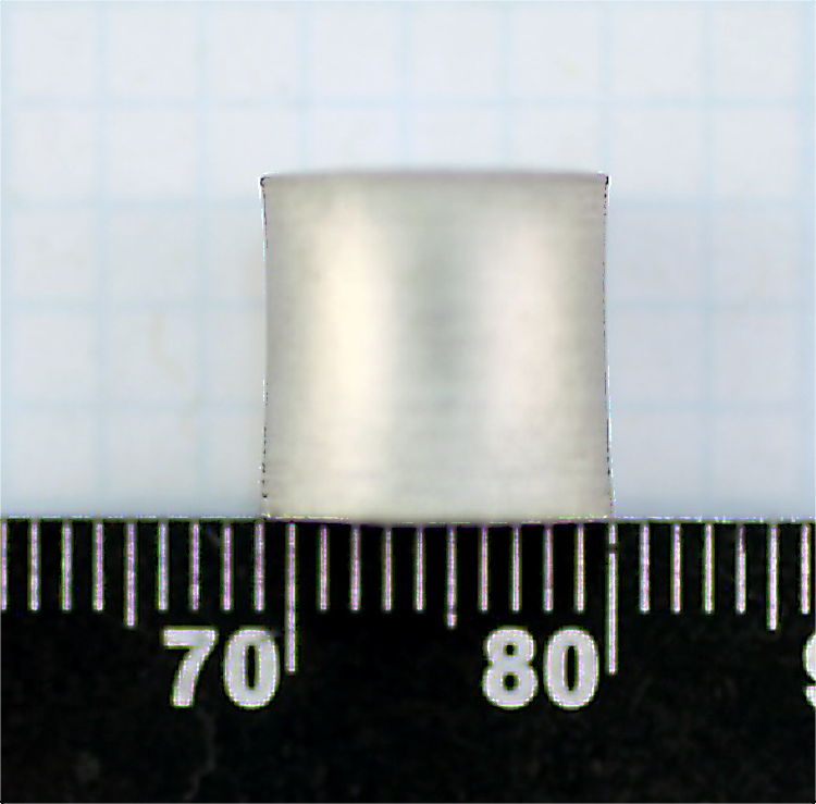
The matrix (Ni, Cu, Mn) powders were mixed in the desired ratios, mechanically alloyed, and milled with tungsten to homogenize each composition. Logs were formed using cold isostatic pressing at 203 MPa. The logs were pre-sintered for 60 minutes (with heating hold of 60 minutes at 900°C) at 1,050°C in hydrogen, giving 63 percent density. The logs were then machined into 12 mm diameter by 12 mm high right circular cylinders with typically 13 g mass at an average 9.8 g/cm3 density. Each sample was cleaned (ethanol), dried, measured for height, diameter at four 45° rotation locations, mass, and vacuum desiccated. A 70W sample (70 wt. % tungsten) is shown in Figure 3, with the “top” registration notch evident.
Laboratory sintering trials show solid migration to the bottom, liquid migration to the top, and considerable pore annihilation. In microgravity, we expect difficulty with densification due to pore coalescence and the absence of pore buoyancy forces. Also, in µg the solid skeleton has less structural rigidity since the solid grains have reduced interparticle compression. The nominal sintering force from surface energy and feature size is 2.2 MPa acting to pull the particles together. Along the vertical axis, the 12 mm sample height at nominally 9.8 g/cm3 density contributes stress at the particle contacts due to gravity in the form of an interparticle compression stress σC defined as follows:

where D is the particle size (5 µm) and X is the interparticle-bond diameter. Setting the gravity-induced compression stress to the 2.2 MPa sintering stress shows gravity is a significant additional stress acting on the particle contacts that are oriented perpendicular to the gravitation vector. As the interparticle bonds grow, the enlargement of X reduces the compressive stress. As an example, solving for when the gravity compressive stress is the same as the sintering stress, by letting σC = 2.2 MPa, results in D/X = 44. For a 5 µm powder this corresponds to X = 0.11 µm. In other words, significantly more sintering and early-particle bonding is expected in the presence of gravity, leading to more structural rigidity to resist distortion while contributing pore buoyancy to eliminate porosity. When gravity is missing, there still is a sintering stress due to capillarity. But the loss of compressive stress on the structure reduces the strong solid-solid bonds that help resist distortion. As another factor, we conjecture the degree of distortion should vary with the dihedral angle. Thus, the design of experiments includes this factor.
Thus, the design of experiments relies on changing the tungsten content to control the solid:liquid ratio at the sintering temperature (roughly the wt. % matrix times 2 gives the vol. % liquid; 30 wt. % results in 50 to 56 vol. % matrix). The alloys range from 70 to 90 wt. % W. The Ni:Cu ratio is adjusted to change the dihedral angle (measured to change from 28° to 41°). Six hold times are employed to capture the sintering evolution. In dilatometry trials and laboratory batch trials, sintering for 1,200°C took the high liquid content (70 and 80 wt. % W) alloys to essentially full density in 60 min of vacuum sintering. Short microgravity experiments are not useful in isolating the gravity effect since the viscosity of the tungsten alloys varies during densification, dropping to about 109 to 1,010 Pa·s [22]. A distorted ground-based sample is shown in Figure 4 after heating to 1,200°C for 60 min in vacuum. The anisotropic shrinkage is largely due to gravity accumulation that induced restrictive shrinkage due to substrate friction. Earlier finite element models were successful in explaining this final shape, but now the challenge is to include variable gravity levels [23-26].
The test matrix consists of 70, 80, 85, and 90 wt. % tungsten samples and three matrix composition ratios where Ni:Cu:Mn is 1.2:0.8:1 (L for low Cu), 1:1:1 (B for base composition), or 0.8:1.2:1 (H for high Cu). The Mn lowers the sintering temperature while the Ni:Cu ratio adjusts the dihedral angle nominally from 28 to 41°. Tungsten is more soluble in nickel-rich liquids, so the high-nickel content will allow more grain boundary wetting, and the low nickel content then gives different grain boundary wetting. Cartridge C0 is designed to reach the temperature (about 1,180°C), where dilatometry first indicates densification. This will document the sample condition prior to significant densification. Cartridges C1 to C6 provide time increments near 1,200°C to nominally capture the sintering trajectory up to an hour. Actual times are calculated using finite elemental thermal analysis pegged to ground sintering trials.
Hardware
The samples are isolated in pure alumina crucibles that allow stacking, with seven samples per assembly. Similar ideas proved successful in prior microgravity experiments. Each crucible is oversized to allow free motion (expansion due to swelling and contraction due to shrinkage) during the flight. Unfortunately, early microgravity experiments only anticipated shrinkage, so crucible contact restricted distortion.
The stack is loaded into a quartz tube, vacuum outgasses, and sealed under vacuum. A fibrous ceramic packing is used to provide a cushion for expansion and contraction. The stacking idea is evident in Figure 5. This assembly is inserted into a molybdenum – 41% rhenium plasma sprayed sleeve over a zirconium boride lined alumina mandrel. Each cartridge assembly has three type N thermocouples accurate to ±2°C.
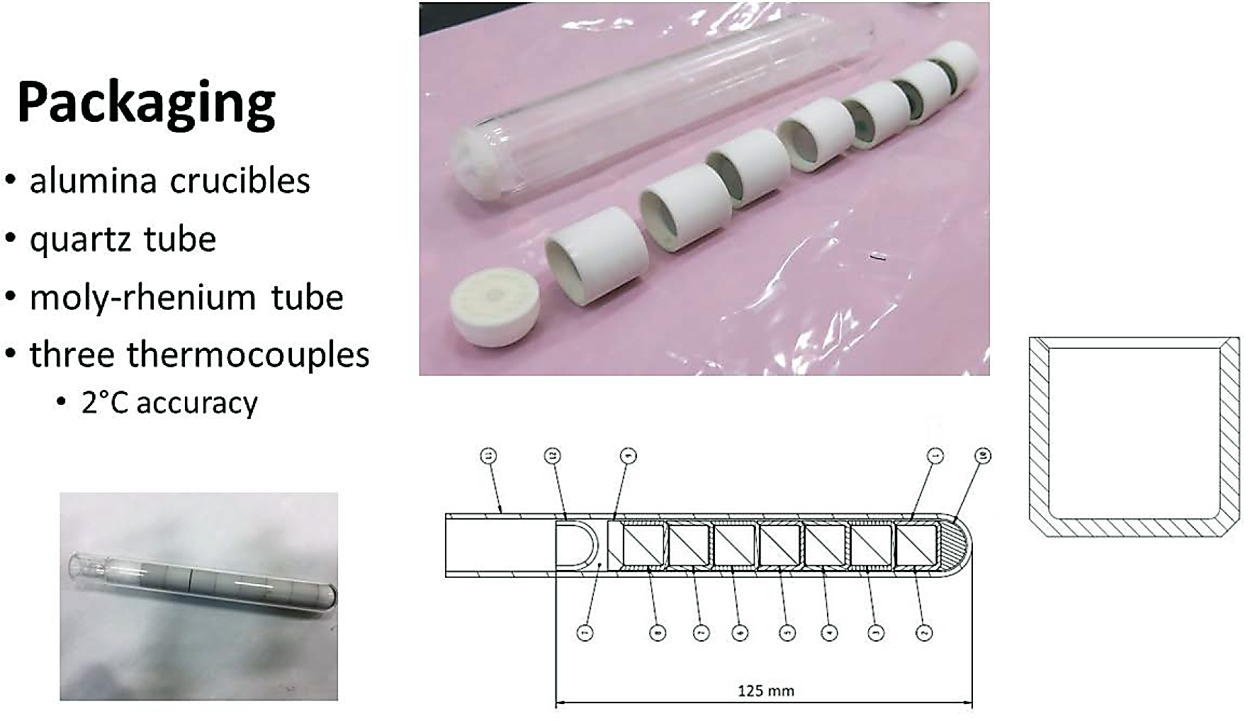
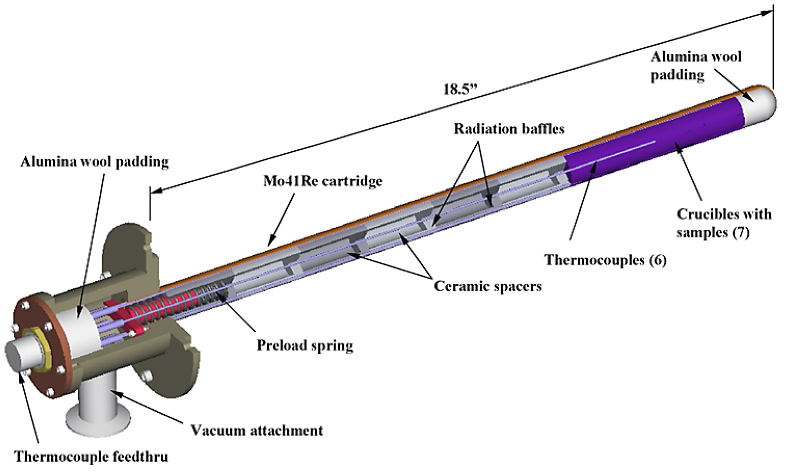
A layout of the assembly is given in Figure 6.
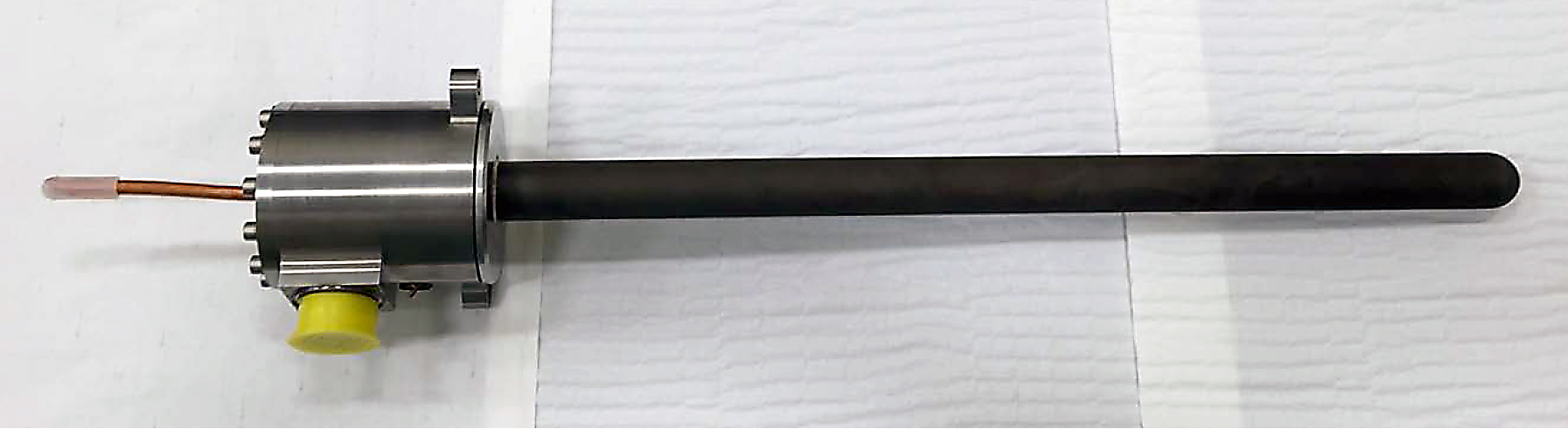
A photograph of the assembled cartridge is given in Figure 7. The overall length is planned to be 575 mm.
Ground Proof
Trials were conducted to prove out the hardware, cartridge integrity, and experiment design. An early problem in 1g was sample sticking to the crucible, largely cured by more care in sample placement and cartridge handling. Some early quartz containers ruptured, and this was cured by adding fibrous ceramic packing in at the end of the sample stack. Instrumentation provided data for thermal analysis, and that identified a role of the adiabatic zone temperature on the temperature profile in the crucible stack. Off-gassing was a concern, as cartridge gas emission peaked just as the sintering temperature was reached. Since much of the cartridge is not involved in sample containment, the decision was to lower the adiabatic zone temperature to 1,050°C to reduce gas loads. Finally, oxidation of the manganese is a remaining concern, where the oxygen is transferred from the tungsten to manganese, since this is a volatile oxide. Thus, the hydrogen treatment used in sample fabrication.
Samples from 1g trials were analyzed for density, distortion, and microstructure. Dimensions are captured using a touch probe coordinate measuring machine. Figure 8 shows the sintered samples, and traces the starting 12 mm by 12 mm size and the sintered size. The top example is 85 wt. % W (85W), next is 80W, and the bottom is 70W. The rest of the sample designation identifies the ratio of matrix (L, B, or H as mentioned earlier) and the sequential identifier number of the approximately 20 replica samples. The selection of samples for flight versus ground was largely random. During test development, secondary quality samples were used to help understand the thermal load and to cure experimental difficulties. Various parameters are calculated to summarize the findings. For example, distortion is calculated from the nonuniform final dimensions.
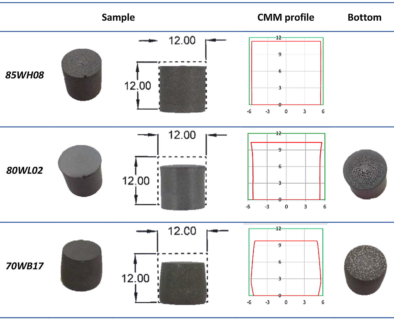
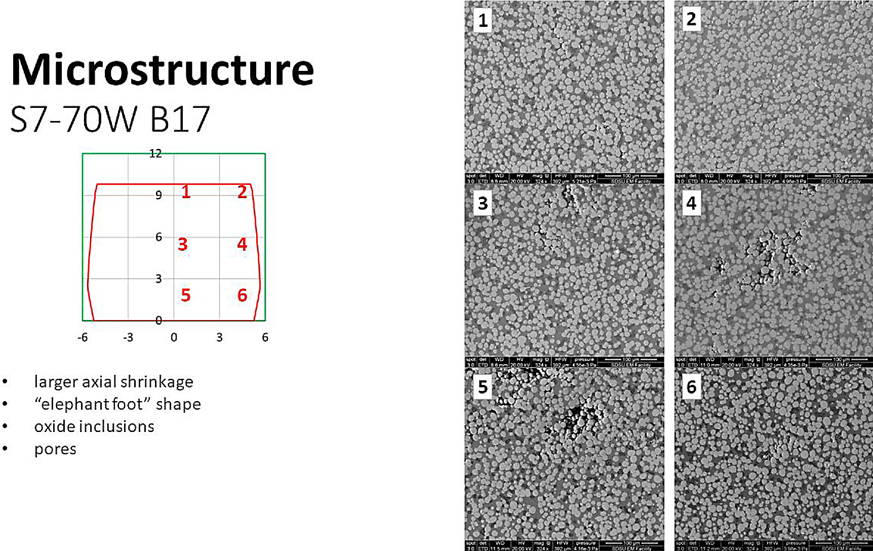
Segregation of solid is detected in the microstructures. For example, the 80W composition had a 0.956 ratio of tungsten at the top versus the bottom (bottom had more tungsten as expected), indicating settling of the dense grains along the gravitational vector. The higher liquid contents distorted more, and the classic elephant foot shape was noted. The progressive increase in compressive stress with position from the sample top caused spreading of the body, but friction with the substrate resisted spreading at the bottom. Figure 9 provides micrographs and dimensional traces for a 70W sample. The micrograph locations are marked by the red numbers on the sintered profile.
The real payoff comes when microgravity sintered samples are returned for comparison.
Simulations
Finite element analysis for temperature versus time and position is employed to ensure the experiments match the desired science parameters. This requires detailed analysis of dimensions and materials so that relevant thermal attributes were included. Material properties include cartridge, thermocouple, ampoule, crucible, and sample properties of emissivity, opacity, conductivity, density, and specific heat.
Adjustments made to the adiabatic cold zone help adjust sample thermal profiles. Various heating and hold cycles enable calculation of the thermal history for each sample in each cartridge. Calibration of the model relies on test data taken during the ground based MUGS trials. The type of thermal profile simulated is illustrated in Figure 10.
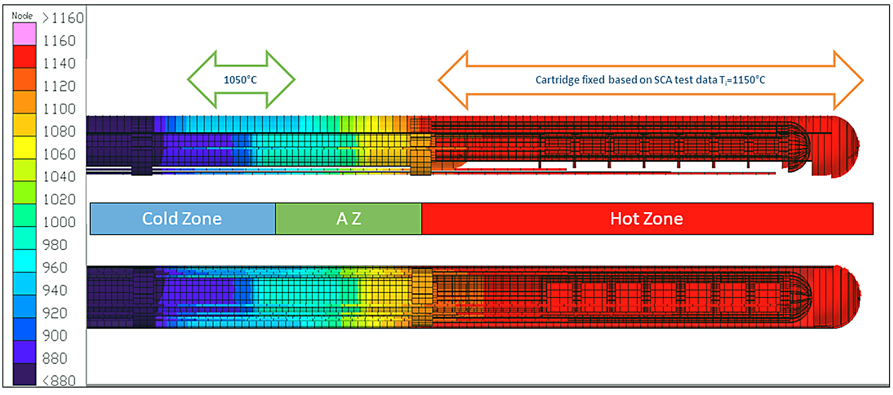
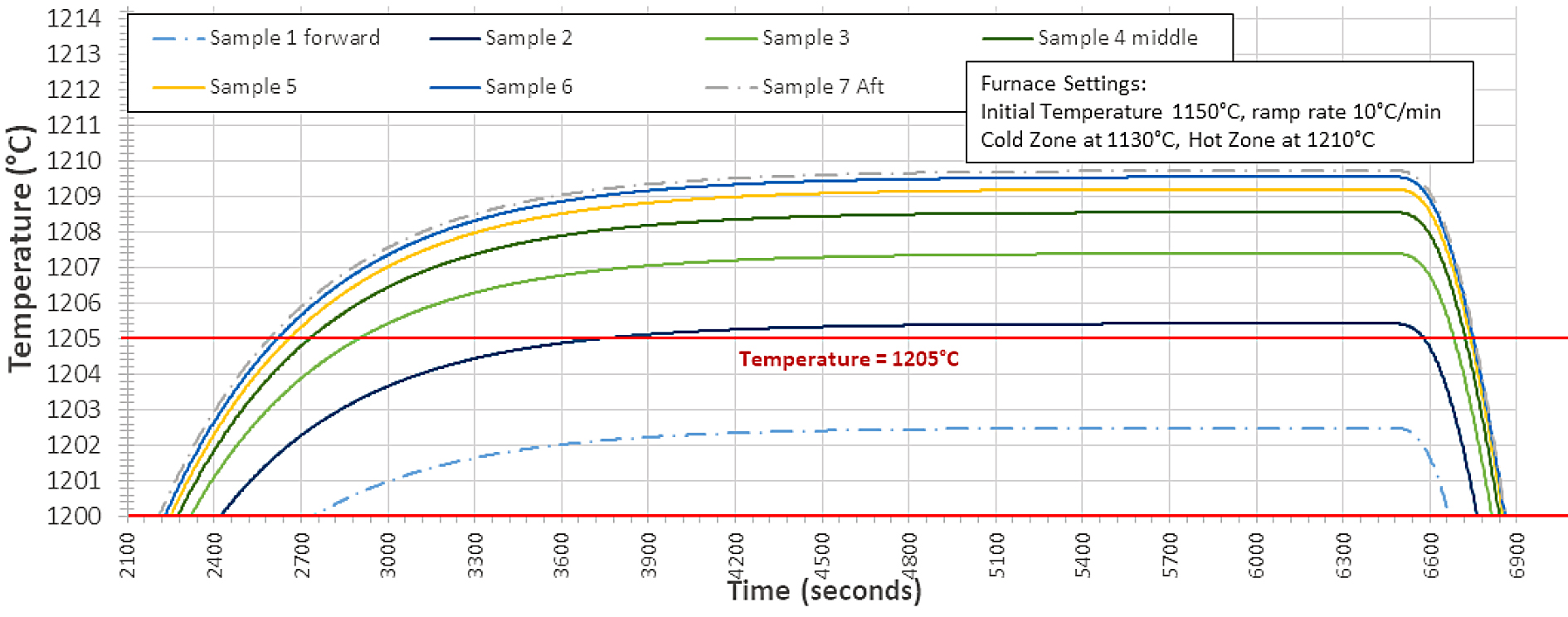
Test data and simulation predictions compare favorably. In the hot zone the finite element analysis proved as accurate as the thermocouple capability. An example of the plots of heating versus position and time are given in Figure 11. On this basis, final decisions were made on the heating cycles.
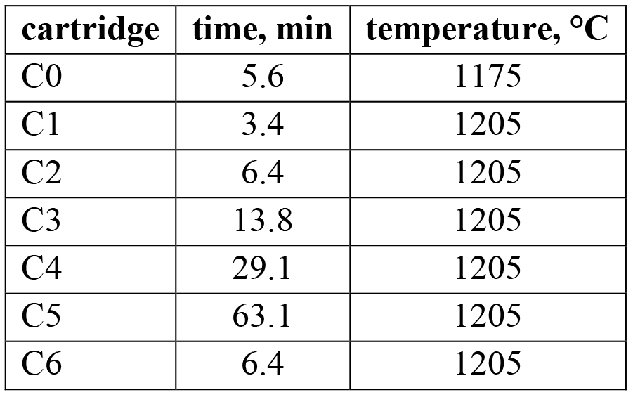
Nominally, the thermal cycle results are summarized in Table 2 below benchmarked to Sample 3 in the stack. In each cartridge the peak temperature and exposure time varies with position. Note the intent is to capture sintering from the onset C0 in logarithmically spaced time intervals to 60 min C5, with C6 being a spare that can be used as a replica run for C2.
Flight Details
The rare opportunity to perform microgravity sintering is a reality. The samples are fabricated, packaged, and the flight cartridges are on the ISS (International Space Station). It is a long process to reach this status, and one that requires diligence and a tremendous support team. The first cartridges on SpaceX CRS-14 (Commercial Resupply Service) launched April 2, 2018, as part of the nearly three-ton payload. The second launch is on SpaceX CRS-15.
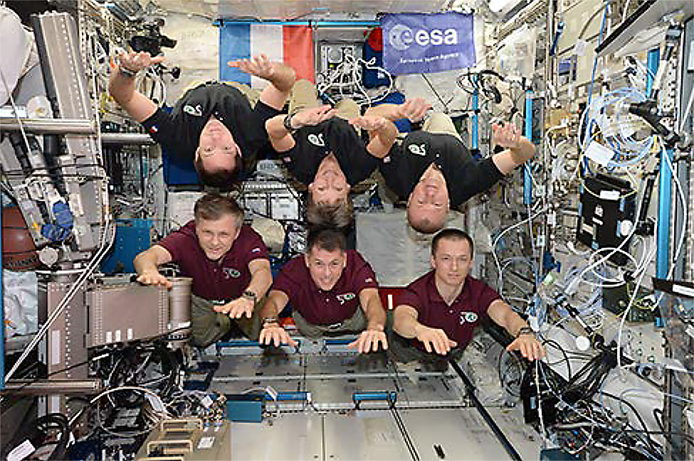
Return of all sintered cartridges from ISS was targeted by December 2018. During the mission, payload specialists, such as shown in Figure 12, inserted and swapped out the cartridges, placing the sealed samples in padded suitcases for return to Earth. There was no measurement burden on the crew.
The project ends in December 2019. The research team has much analysis and modeling to perform when the samples are returned. There is nothing routine about extraterrestrial sintering, so we can only anticipate more surprises. Conceptualizations of extraterrestrial sintering using lunar or Martian resources are important to realize if exploration is to advance, and one must realize the current experiments are baby steps toward the eventual launch of robots for sintering materials harvested off-world [27].
Acknowledgements
We are appreciative of the support team at the Marshall Space Flight Center that provides technical and management support for these experiments (NNX16AK21G). The project is conducted under the guidance provided by Biliyar Bhat, Shawn Regan, and Jan Rogers.
References
- F. V. Lenel, H. H. Hausner, O. V. Roman, G. S. Ansell, “The Influence of Gravity in Sintering,” Transactions of the Metallurgical Society (AIME), 1963, vol. 227, pp. 640-644.
- F. V. Lenel, H. H. Hausner, E. Hayashi, G. S. Ansell, “Some Observations on the Shrinkage Behaviour of Copper Compacts and of Loose Powder Aggregates,” Powder Metallurgy,1961, vol. 4, pp. 25-36.
- H. S. Waff, “Effects of the Gravitational Field on Liquid Distribution in Partial Melts within the Upper Mantle,” Journal of Geophysical Research, 1980, vol. 85, pp. 1815-1825.
- A. N. Niemi, T. H. Courtney, “Settling in Solid-Liquid Systems with Specific Application to Liquid Phase Sintering,” Acta Metallurgica, 1983, vol. 31, pp. 1393-1401.
- Z. Fang, B. R. Patterson, M. E. Turner, “Influence of Particle Size Distribution on Coarsening,” Acta Metallurgica et Materialia, 1992, vol. 40, pp. 713-722.
- L. B. Ekbom, “Results from the Melting of Tungsten Composites Under Microgravity in Space (Texus 10 Flight),” International Journal of Refractory Metals and Hard Materials, 1987, vol. 6, pp. 231-232.
- [7] C. M. Kipphut, A. Bose, S. Farooq, R. M. German, “Gravity and Configurational Energy Induced Microstructural Changes in Liquid Phase Sintering,” Metallurgical Transactions, 1988, vol. 19A, pp. 1905-1913.
- J. Liu, Y. Liu, A. Lal, R. M. German, “Shape Distortion Induced by Gravity in the Initial Stage of Solid Phase Sintering,” Scripta Materialia, 1999, vol. 40, pp. 1221-1227.
- O. Lame, D. Bouvard, H. Wiedermann, “Anisotropic Shrinkage and Gravity Induced Creep during Sintering of Steel Powder Compacts,” Powder Metallurgy, 2002, vol. 45, pp. 181-185.
- R. M. German, R. G Iacocca, J. L. Johnson, Y. Liu, A. Upadhyaya, “Liquid Phase Sintering under Microgravity Conditions,” Journal of Metals (JOM), 1995, vol. 47, no. 8, pp. 46-48.
- Z. Xue, S. L. Noojin, J. G. Vanderfrift, A. K. Kuruvilla, J. E. Smith, “Microgravity Liquid Phase Sintering and Pore Evolution,” Materials Transactions, 1996, vol. 37, pp. 1084- 1090.
- Y. Liu, R. G. Iacocca, J. L. Johnson, R. M. German, S. Kohara, “Microstructural Anomalies in a W-Ni Alloy Liquid Phase Sintered Under Microgravity Conditions,” Metallurgical and Materials Transactions, 1995, vol. 26A, pp. 2484-2486.
- P. Lu, R. M. German, R. G. Iacocca, “Presintering Effects on Ground-Based and Microgravity Liquid Phase Sintering.” Metallurgical and Materials Transactions, 2001, vol. 32A, pp. 2097-2107.
- R. M. German, J. L. Johnson, “Replication Experiments in Microgravity Liquid Phase Sintering,” Metallurgical and Materials Transactions, 2016, vol. 47A, pp. 2286-2299.
- M. R. Wegmann, E. Olson, W. Z. Misiolek, “Dimensional Control in Powder Injection Molded Fe2%Ni,” Advances in Powder Metallurgy and Particulate Materials – 1993, vol. 5, Metal Powder Industries Federation, Princeton, NJ, 1993, pp. 133-142.
- W. E. Gurwell, “Heavy Metal Alloys Containing 30% to 90% Tungsten,” Progress in Powder Metallurgy, 1985, vol. 41, pp. 327-346.
- J. A. Alvarado-Contreras, R. M. German, A. L. Maximenko, E. A. Olevsky, “Coupled Densification-Shape Distortion Analysis of Liquid Phase Sintering Affected By Gravity,” Metallurgical and Materials Transactions, 2014, vol. 45A, pp. 927-933.
- J. A. Alvarado-Contreras, E. A. Olevsky, A. L. Maximenko, R. M. German, “Kinetics of shrinkage and shape evolution during liquid phase sintering of tungsten heavy alloy,” Journal of Materials Science, 2014, vol. 49, pp. 1130-1137.
- J. A. Alvarado-Contreras, E. A. Olevsky, R. M. German, “Modeling of Gravity Induced Shape Distortions during Sintering of Cylindrical Specimens,” Mechanics Research Communications, 2013, vol. 50, pp. 8-11.
- T. H. Young, W. Li, E. A. Olevesky, J. McKittrick, R. M. German, “Densification and Distortion of Tungsten Heavy Alloys Using Low Sintering Temperatures,” Advances in Powder Metallurgy and Particulate Materials – 2012, Metal Powder Industries Federation, Princeton, NJ, 2012, part 5, pp. 34-44.
- R. M. German, “Lower Sintering Temperature Tungsten Alloys for Space Research,”International Journal of Refractory Metals and Hard Materials, 2015, vol. 53, pp. 74-79.
- R. M. German, P. Suri, N. Erhardt, S. H. Chung, “Gravitational Effects on Distortion in Liquid Phase Sintering, “ Advances in Powder Metallurgy and Particulate Materials – 2004, Part 5, Metal Powder Industries Federation, Princeton, NJ, 2004, pp. 41-50.
- R. Ganesan, A. Griffo, R. M. German, “Finite Element Modeling of Distortion during Liquid Phase Sintering,” Metallurgical and Materials Transactions, 1998, vol. 29A, pp. 659-664.
- R. Raman, R. M. German, “A Mathematical Model for Gravity-Induced Distortion during Liquid Phase Sintering,” Metallurgical and Materials Transactions, 1995, vol. 26A, pp. 653-659.
- C. Binet, K. L. Lencoski, D. F. Heaney, R. M. German, “Modeling of Distortion during LPS Using Navier-Stokes Equations Coupled with a Free Surface,“ Proceedings Sintering 2003, C. Cornwall, R. M. German, G. Messing (eds.), Materials Research Institute, Pennsylvania State University, University Park, PA, 2003.
- S. J. Park, S. H. Chung, J. L. Johnson, R. M. German, “Distortion Simulation of Liquid Phase Sintering on Earth, on the Moon, on Mars, and In Space,” Advances in Powder Metallurgy and Particulate Materials – 2006, Metal Powder Industries Federation, Princeton, NJ, 2006, Part 5, pp. 14-24.
- M. P. Bodiford, M. R. Fiske, W. McGregor, R. D. Pope, “In Situ Resource-Based Lunar and Martial Habitat Structures Development at NASA/MSFC,” Proceedings American Institute of Aeronautics and Astronautics First Exploration Conference, Orlando, FL, 2005, paper AIAA-2005-2704.
Reprinted from Advances in Powder Metallurgy & Particulate Materials — 2018, ISBN 978-1-943694-15-0, © 2018 Metal Powder Industries Federation, 105 College Road East, Princeton, New Jersey, USA.


 general practice for CQI-9 and AMS2750E")


