


Newly employed heat-treat engineers, designers and practitioners may need an appreciable amount of time to gain the required knowledge and experience in understanding the subtleties of induction hardening. Underestimating specific geometrical features of parts and hardness patterns by novices, as well as negligence in understanding an impact of different process factors on the outcome of heat treatment may produce faulty results. Finding that your completed parts have cracked after heat treating is frustrating, wasteful, and expensive. The goal of this two-part article is to minimize the impact of a workplace generation gap by helping new induction heat-treat professionals better understand the factors related to steel cracking and the actions to be taken to avoid it.
It is important to learn that crack initiation within the heat-treated components, its growth, and propagation is affected by a number of factors. This includes specifics of the component’s geometry, its chemical composition and microstructure, processing temperatures, quenching subtleties, hardness pattern, inductor design, magnitude and distribution of initial, transient and residual stresses, design of tooling/fixtures, etc. Cracking can be caused by a single factor or by an undesirable combination of several factors.
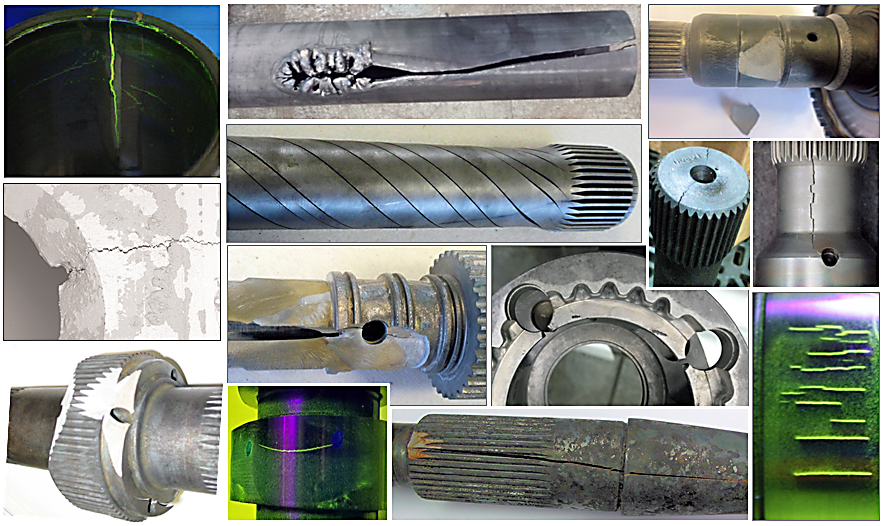
There is virtually an endless variety of components that are routinely induction hardened (IH). Certain geometries may be associated with a tendency toward crack initiation requiring careful selection of process recipes and an equipment design. As an example, Figure 1 shows a few examples of typical cracks caused by improper process recipes or inductor designs or that have been caused by underestimation by heat-treat practitioners on specific geometrical features of heat-treated components.
Cracking and fractures can be classified in different ways, including ductile and brittle fractures, environmentally affected crack initiation, fatigue fractures, delayed crack initiation, and others. It would be appropriate to review a case study at this point.
Case study
A heat treater had a run-off of an induction hardening machine on a Friday evening. All components that had been induction hardened were checked, and no problem had been found. NDT eddy current testing, as well as magnetic particle inspection (MPI), did not reveal any presence of cracks. However, after the weekend, it was found that a certain percentage of heat-treated parts developed cracks just sitting on a pallet. This is a typical example of delayed crack initiation, and measures should be taken to prevent such failures. Other examples of delay cracking may be associated with fractures that occur during assembly of heat-treated parts.
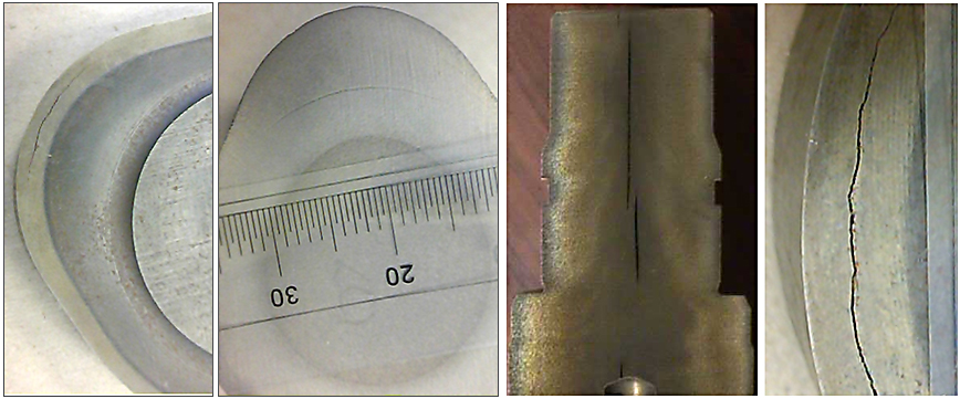
Some practitioners may also distinguish transverse, longitudinal, or circumferential fractures, as well as surface cracks vs. subsurface or internal cracks. As an example, Figure 2 illustrates subsurface cracking, which often are not visible to the naked eye, and only appropriate NDT inspection (e.g., ultrasound/acoustic inspection) or destructive examination may reveal their presence in order to prevent a premature failure of the component during its service life.
In recent years, light-weighting initiatives have become common in automotive, off-road, and agricultural vehicle designs, as well as aerospace and other industries. To minimize weight and cost of steel components, designers might choose to drill holes, reduce cross sections, make grooves, cutouts, and re-entrant corners, as well as to use custom shapes and alloys to accomplish these goals [1]. In some cases, in an attempt to reduce costs, designers create a component’s geometries that might be prone to cracking during heat treating.
Failure analysts are also dealing with parts that failed prematurely in service. Why? Perhaps something had not been done properly during heat treating or perhaps inadequate equipment and/or a process recipe were used for a particular component without appropriately addressing its geometrical features or hardness pattern requirements resulting in a compromised outcome of the heat treatment that might not be easy to detect.
Factor of Component’s Geometry
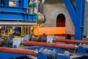
Induction scan-hardening is one of the most popular techniques to strengthen steel components. An increased popularity of scan-hardening is associated with several distinguished advantages of this technology, including but not limited to a lower capital cost compared with alternative processes. Scan hardening exhibits impressive process flexibility with respect to the workpiece length and, to some extent, variations in a part’s diameter. In scan hardening, the inductor or workpiece (or both) can move linearly relative to each other during the hardening cycle [2]. Depending on workflow, the system can be built vertically, horizontally, and at an angle, though vertical-scan hardening is the most popular design for a number of reasons, including a reduced equipment footprint and natural quench flow due to gravity.
The advantage of scan hardening is that only a small portion of a component’s needed hardened length is heated at a given time, enabling the hardening of elongated parts using relatively small (and generally less expensive) power supplies. Conventional scanning systems offer the ability to vary scanning speed and power during the process, which controls the amount of heat applied to different areas of the workpiece. Induction scanners incorporate a number of different elements with inductor design, quenching conditions, and power supply having the most significant impact on hardening results.
Geometrical irregularities and discontinuities (that are very typical for a great majority of modern components) can distort the electro-magnetic field generated by an inductor, potentially causing several undesirable phenomena associated with reaching excessive temperatures and thermal gradients.
Overheating is one of the most common causes of cracking. Extreme temperatures result in grain boundary liquation (incipient melting) associated with liquation of low-melting phases and steel’s impurities concentrated at grain boundaries, leading to a degradation of those boundaries. Weakened grain structure significantly increases the steel’s brittleness, sensitivity to developing intergranular cracking, and negatively affects the overall metallurgical outcome of IH [2].
The phenomenon of grain boundary liquation can be amplified by the segregation of manganese, sulfur, copper, and some other elements to the austenitic grain boundaries. Both phosphorus and sulfur markedly affect the steel overheating temperatures, increasing steel’s tendency for a crack initiation.
As an example, Figure 3 (left) illustrates steel microstructures exhibiting grain boundary liquation. A network (chains) of liquated areas located at the grain boundaries is easily visible. As a comparison, the image in Figure 3 (right) shows a so-called “clean” structure.
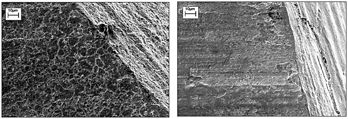
Different magnitudes of overheating cause various degrees of grain boundary liquation and are commonly designated as slight, moderate, or severe. This designation is relatively subjective and might be different for different corporate standards.
Certain geometrical features could make a component become prone to localized heat surpluses during austenitization, which could cause a crack initiation during subsequent spray quenching. Longitudinal or transverse holes, keyways, flanges, undercuts, splines, sharp edges, shoulders, and corners are typical examples of such geometrical irregularities and discontinuities.
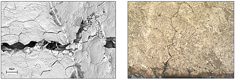
Nevertheless, such features are not unique as they are commonly found on many transmission and engine components [1,2]. Therefore, it might be unavoidable to have a certain degree of incipient melting at grain boundaries when induction hardening complex geometries. In cases like this, some corporate standards might allow a slight amount of grain-boundary liquation. The presence of compressive residual stresses of appreciable magnitude that is quite typical in induction surface hardening applications is often sufficient in preventing “opening” slightly liquated grain boundaries. Severe grain boundary liquation must be avoided, because it is associated with extreme brittleness, notch sensitivity, and poor fracture toughness, leading to failure caused by intergranular cracking (Figure 4).
Factor of Inadequate Selection of Equipment
and/or Process Parameters
Another example of an impact of very common geometrical irregularities on results of heat treatment would be a scan hardening of stepped shafts consisting of multiple diameter changes, sharp shoulders, as well as a combination of solid and hollow sections and wall thickness changes. The user may also specify appreciably different hardness case depths along the length of a workpiece for multifunctional, complex geometry components.
All these geometrical features are quite typical and can produce unwanted deviations in hardness patterns, metallurgical structures, magnitude, and distribution of stresses, which could unfortunately develop favorable conditions for a grain boundary liquation and a crack development. Therefore, a capability to control not only heating intensity but also the depth of heat generation during scan hardening is imperative for a great majority of modern IH applications.
Temperature distribution across the radius/thickness of a workpiece is primarily a function of the applied frequency, power density, and the heat time/scan rate. Frequency is a single most critical factor that affects the depth of heat generation in induction heating, because frequency determines depth of eddy current penetration. In addition, the frequency exhibits a potent impact on a reduction of heat surpluses when dealing with the most geometrical irregularities and discontinuities.
In a majority of cases, an optimal frequency that would appropriately address all geometrical features and hardness depth requirements of modern components simply does not exist. This is why conventional scan hardening equipment applying a fixed frequency must always compromise between achieving the desired metallurgical quality, process capability, production rate, distribution, and magnitude of transient and residual stresses as well as developing structures free of cracking and excessive distortion.
Besides that, global competitiveness demands that heat treaters be extremely flexible. Long-term customers may move their production at a minute’s notice, and heat treaters must be flexible to a market demand [1]. For example, today, you might need to surface harden 12 mm (∼0.5 in.) diameter pins with an effective hardness case depth of 1.6 mm (0.0625 in.). This would normally require a frequency in the 50-60 kHz range. Tomorrow, the product might change, and you need to run a 30 mm (1.2 in.) diameter shaft with a nominal 5 mm (0.2 in.) hardness case depth requiring a frequency of 5 to 7 kHz range to ensure more in-depth heat generation. However, the day after that, you might need to through-harden both: 8 mm and 25 mm diameter pins.
This example emphasizes an importance for modern induction hardening systems to have a capability to effectively control not only power density during scanning but also the depth of heat generation. Unfortunately, the majority of commercially available medium- and high-frequency power sources are designed to deliver a certain frequency, which cannot be instantly (practically speaking) and deliberately changed to an appreciable degree during scan hardening [1].
New generations of inverters (Statipower® IFP™) developed by Inductoheat eliminates this drawback and simplifies achieving the required hardness pattern without compromising metallurgical quality [1-3]. This innovative technology enables instant, independent adjustment of power and frequency (5-60 kHz) in a preprogrammed manner during the heating cycle optimizing electromagnetic, thermal, and metallurgical conditions of your products and offering numerous considerable benefits (Figure 5).
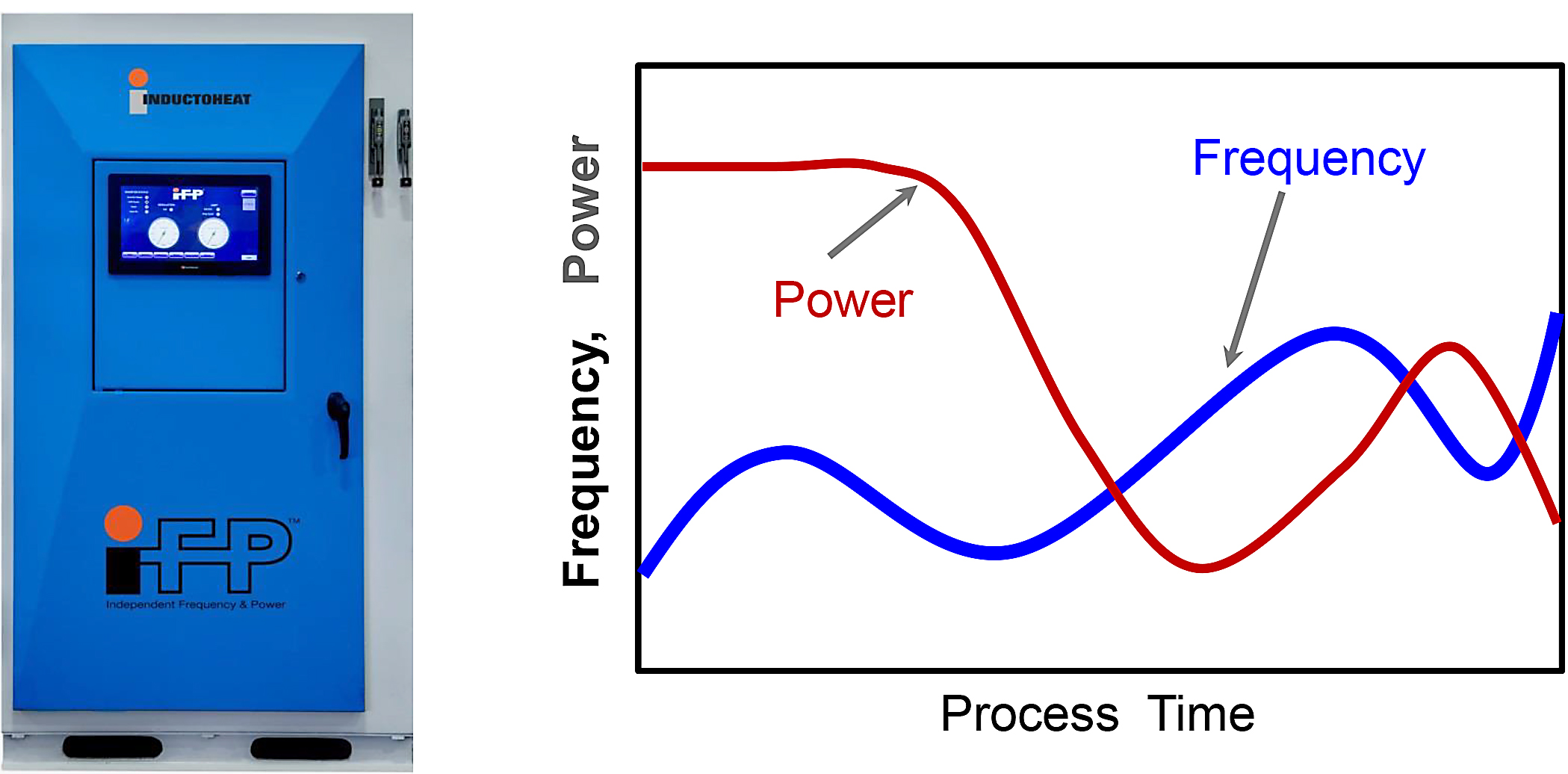
IFP technology (Independent Frequency and Power control) effectively addresses industry needs for cost-effectiveness and superior process flexibility, greatly expanding induction equipment capabilities, simplifying process development, and enhancing metallurgical quality.
Therefore, if one automotive company comes to a processing company and then, a day after tomorrow, another one with a totally different requirement needs processing; a component supplier would be able to process those parts using the same equipment available at their shops.
In induction heat treating, the coil is commonly dedicated to a particular component’s geometry, but its cost is relatively small compared to the cost of the entire system and, in particular, an inverter. Thus, if the power supply will provide greater flexibility, then it will be a big cost-saving deal in our highly competitive world. The extent of projects that can be undertaken with Inductoheat’s patented technology is widening as the company works to introduce new models that expand coverage of different ranges of frequencies and maximum powers.
Stresses, Their Appearance, and Impact
on Crack Initiation and Propagation
Stresses are prime causes of cracking. It is imperative to have a clear understanding regarding nature and causes of stresses while discussing a subject of cracking in heat treating.
Stresses can be classified in several different ways. Depending on the distance over which they extend, stresses can be “macroscopic” or “microscopic.” Macroscopic stresses typically appear at a distance that exceeds several grains. In contrast, microscopic stresses take place within a grain and include stresses that appear on the atomic level. Studies of residual stresses in steel heat treating typically focus on the distribution and magnitude of macroscopic stresses [1,4].
On the basis of their cause in IH, several types of stresses are encountered, including thermal stresses, phase transformation stresses, and applied stresses. Thermal stresses are caused by different magnitudes of temperature and thermal gradients, as well as unequal metal expansion/contraction.
Phase transformation stresses primarily occur because of volumetric changes accompanying the formation of different phases such as austenite, bainite, martensite, and others.
Applied stresses during IH are associated with the specifics of tooling/fixture of heat-treated components during heating and quenching. For example, cylinder workpieces (such as shaft surface hardening) experience compressive and torsion stresses during their rotation in single-shot or scan-hardened systems.
In applications requiring through hardening, a workpiece firmly held between two holders, centers, or nests, will “try” to expand during the heating cycle, potentially causing disproportionate applied stresses and developing favorable conditions for an excessive distortion (due to buckling) and potential cracking. Allowing for a part growth by using a low-pressure spring on one of support/tooling end could help reduce those stresses and solve this problem.
Although stresses are three dimensional (3D) in nature, having axial, circumferential (hoop), and radial components, a discussion is often simplified by considering them as one-dimensional stresses (highest magnitude stress).
On the basis of the timing of their appearance, stresses can be divided into three groups: initial, transient, and residual stresses.
Initial stresses. Initial stresses are “hidden” within the “green” part. Their distribution and magnitude depend on the manufacturing steps preceding IH (casting, forging, welding, rolling, upsetting, drawing, etc.). For example, the maximum of tensile stresses is commonly located in the core of hot-forged components. During heating, initial stresses of appreciable magnitude may combine with transient stresses and develop crack initiation resulting in subsurface cracking. Thus, if in doubt, stress relieving of a workpiece before IH should be done.
Transient stresses. In addition to initial stresses, there are transient stresses, which occur during IH due to volumetric expansions and contractions associated with temperatures, thermal gradients, and the phase transformations. Our experience shows that in IH, the transient stresses are responsible for the great majority of cracking.
Residual stresses. These stresses remain within the workpiece after the IH process is completed. Thus, residual stresses are the product of initial and transient stresses, and they exist in an absence of external force or temperature gradients. In many cases, these stresses can be very beneficial, complementing desirable microstructural changes in providing needed engineering characteristics. In other cases, magnitudes and the distribution of residual stresses may be harmful, increasing crack sensitivity, facilitating crack initiation and propagation, causing delay cracking, and shortening the component’s service life.
These stresses can elevate or reduce the mean stress occurred during the component’s service life. Surface-compressive residual stresses are considered desirable in most applications. Among other factors, these stresses are important for improving the fatigue properties of the workpiece, delaying the crack initiation and the propagation of micro-cracks, and providing desirable protection against geometrical stress risers (e.g., scratches, notches) as well as microstructural heterogeneities. Compressive residual stresses are particularly beneficial to parts that experience bending, impact, and/or torsion in service. They enhance the fatigue resistance because the applied stresses in service are often tensile, and the presence of the compressive residual surface stresses helps minimize the magnitude of the sum of both decreasing the mean stress.
It is important to remember that the residual stress system is self-equilibrating; that is, there is always a balance of stresses within the workpiece owing to static equilibrium. If certain regions have compressive residual stresses, then somewhere else there must be offsetting tensile stresses. If the stresses were not balanced, “movement” would then result; this is bad.
Tensile residual stresses of a certain magnitude and location can be dangerous, making a negative impact on fatigue resistance, and they may also cause stress-corrosion cracking in the presence of a corrosive environment. These stresses are combined with the load stresses in service, amplifying the magnitude of the total stress, which may exceed the strength of material resulting in a crack development.
In applications where only surface hardening is required, the maximum of the tensile residual stress is commonly located just beneath the hardened case within the transition zone, and it is often responsible for subsurface crack initiation.
The greater magnitude of residual tensile stresses of the surface hardened component is usually associated with increased brittleness and notch sensitivity, reduced toughness, and fatigue strength. This is one of the reasons for specifying a stress relief/tempering after IH, which helps reduce the peak of the tensile residual stress and shift it farther from regions of applied stress, while retaining the useful surface compressive stresses.
In contrast, in through-hardening applications, the surface residual stresses are frequently tensile, but under certain quenching conditions, they can be reversed into compression.
Mathematical modeling is an essential tool that helps assess the complexity of transient and residual stress distributions, taking into consideration the intricacy of the kinetics of displacive and reconstructive transformations based on thermodynamic and phenomenological approaches and has been discussed in many publications. Some of the most intensive computer-modeling studies of stresses in induction heat treatment are those conducted by scientists from companies such as DANTE Solutions, Inc.
Fishbone Diagram of Cracking in Induction Hardening
Virtually an endless variety of components routinely induction hardened call for a corresponding, almost endless, variety of process recipes and inductor designs. Each of these components has its own “personality” that affects the outcome of heat treatment, including a propensity to cracking. Figure 6 shows the “fishbone” diagram of cracking and prevention related to IH, revealing the complexity of this very broad subject [2,5].
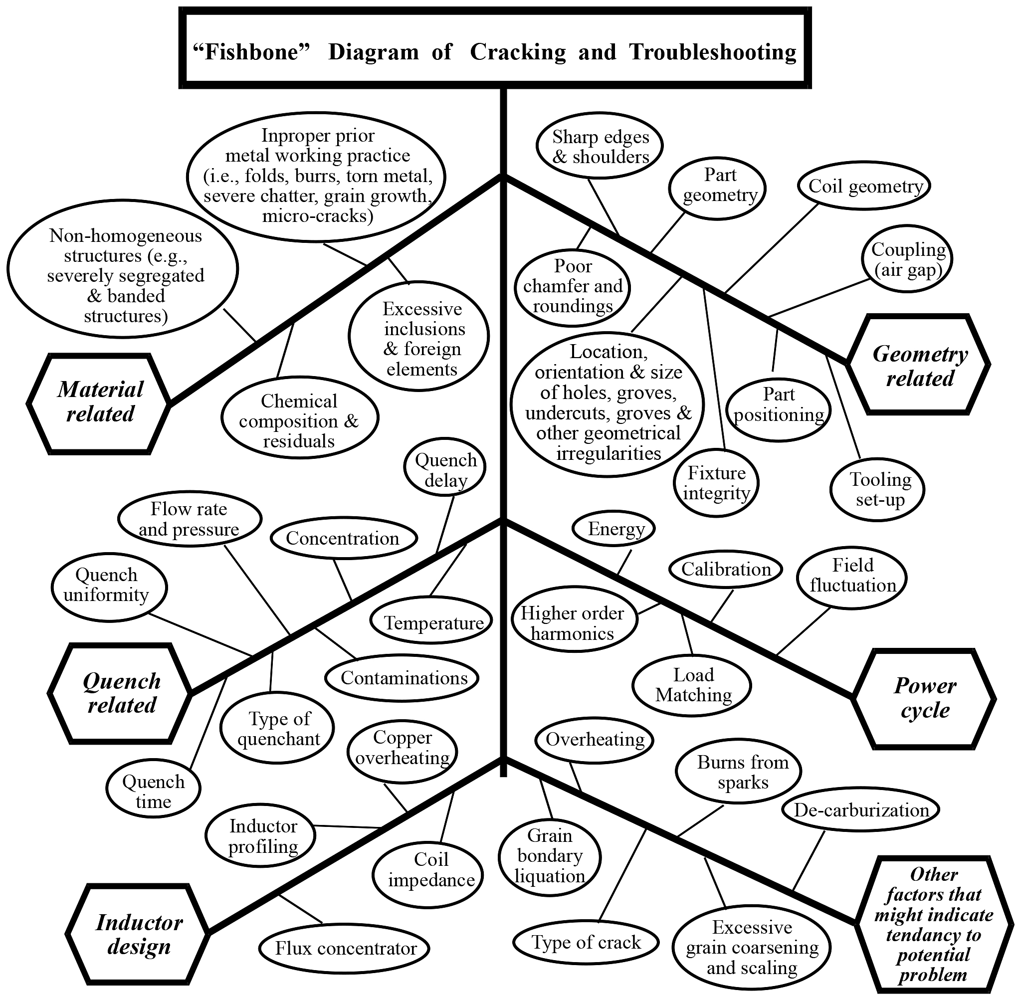
We hope readers of this article would never experience a cracking problem. but if such an event occurs, then this fishbone diagram might be helpful since one or several factors of this diagram might be causing a crack initiation.
As can be concluded from the fishbone diagram, the potential causes of cracking can be categorized into seven main groups:
- Material related.
- Geometry of the workpiece.
- Power/energy cycle (heating stage) and unspecified heating conditions.
- Improper quenching conditions (including quench severity and uniformity).
- Inadequate inductor design.
- Improper accessories, tooling, fixtures.
- Other factors.
Even a cursory look at Figure 6 unveils the intricacy and challenges in determining the root cause and the consequential factors associated with cracking. If cracking occurs, there may be a number of interrelated factors responsible for its appearance. Understanding a broad spectrum of factors associated with various failure modes is an important step in developing crack-free processes. At a minimum, an analyst must have knowledge in failure analysis, electromagnetics, metallurgy, materials science, mechanics, heat transfer, chemistry, spectroscopy, and other disciplines. It is difficult to overestimate an importance to have a sufficient degree of familiarity with the hardening equipment and process specifics of a particular machine under investigation.
Cracks that occur very infrequently are usually the most difficult to fix because some of those occurrences may take place so rarely they may be considered as a statistical event, and their root cause(s) is often associated with previous stages of a manufacturing chain. Each preceding stage of manufacturing exhibits a potential for certain problem(s) for which the IH is sometimes blamed.
It is much easier to determine the root cause of cracking if crack initiation can be turned “on” and “off” by modifying process parameters.
If, for some reason, steel does not respond to heat treatment in an expected way, developing cracking, then one of the first steps in determining the root cause for such unexpected behavior is to make sure the steel has the proper chemical composition, homogeneity, and initial prior microstructure, as well as appropriate thermal history. In some cases, what is supposed to be the same grade of steel purchased from two different suppliers may have appreciable variations of composition and properties.
In real-world needs, producers of IH equipment should have the experience and analysis necessary to help heat-treat practitioners with specific problems.
An interested reader can find numerous publications and words of wisdom shared by industry experts to avoid a part’s cracking. Some of the recommendations and simple remedies to eliminate or minimize the probability of cracking will be outlined and explained in Part 2 of this article.
References
- G.Doyon, V.Rudnev, C.Russell, J.Maher, Revolution – not an evolution – necessary to advance induction heat treating, Advance Materials & Processes, September, 2017, pp. 72-80.
- V.Rudnev, D.Loveless, R.Cook, Handbook of Induction Heating, CRC Press, 2017.
- www.inductoheat.com
- ASM Handbook Volume 11: Failure Analysis and Prevention, ASM International, 1998.
- V.Rudnev, Troubleshooting cracking in induction hardening, Heat Treating Progress, ASM Intl., August, 2003, pp.27-28.
- About the author
- Gary Doyon, Dr. Valery Rudnev, Randall Minnick, and Tim Boussie are with Inductoheat Inc., an Inductotherm Group company.


 general practice for CQI-9 and AMS2750E")


