


The principles behind how and why a thermocouple functions were beginning to be understood in the early 1800s with most significant developments taking place in Europe. In 1800, Alessandro Volta built a voltaic pile of dissimilar metals, silver and zinc, separated by cloth that had been soaked in salt water. This stack created a small electrical current, 1-2 volts. A group of piles, called a battery, could be assembled and connected with metal to provide for a higher current or energy source. The significance of this discovery was that a source of steady and reliable current was now available, and it was understood there was a phenomenon that took place when dissimilar metals were in contact with each other. This enabled others to perform more advanced research with electricity.
Hans Christian Oersted discovered in 1820 that a current of electricity flowing in a wire in proximity to a magnetic needle had the power to move the needle. This led to much interest in experimentation in the mechanical effects of current. Subsequently, Andre Ampere demonstrated that one electric current had a magnetic influence upon another showing that magnetism was an electrical phenomenon.
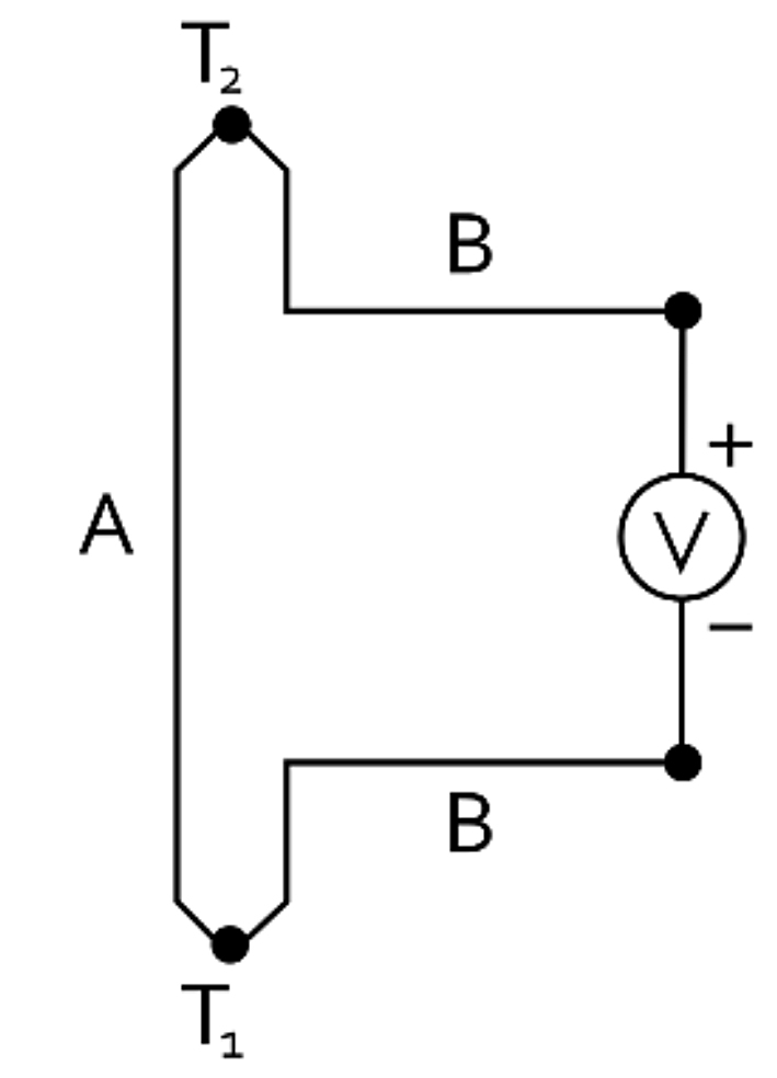
In 1821, Thomas Seebeck announced he had discovered that when two dissimilar metals were placed in a closed loop and one of the junctions was exposed to a change in temperature, an electric current was produced. This production of electromagnetic force and electric current is known as the Seebeck Effect. It was much later before this was fully understood and could be expressed correctly mathematically; however, because of this discovery, Seebeck’s name will forever be associated with the discovery of thermoelectricity and the thermocouple. This electromagnetic force or EMF is the basis for modern day thermocouples. (See Figure 1)
Subsequently, these experiments were repeated and refined by people such as Michael Faraday, George Ohm, Claude Pouillet, and Antoine Bequerel. In fact, Bequerel is the first person known to suggest using Seebeck’s discovery for measuring high temperatures. He proposed the strength of a current generated in these closed loops of dissimilar metals was proportional to the change in temperature. Using a discovery made decades earlier by Humphry Davy that all metals have positive temperature coefficients of resistance and that platinum was an excellent temperature detector, Antoine Bequerel settled on platinum and palladium as the best combination for his experiments. Edmond Bequerel followed up on his father’s work and, in the mid-1860s, used a platinum-palladium thermocouple in conjunction with an air thermometer during research on the melting point of various materials. He also postulated a mathematical expression for the relationship between temperature and EMF as his father had suggested earlier. Peter Tait conducted experiments in thermoelectricity using iridium-platinum alloys and determined small amounts of impurities or even stress on the wire could alter results significantly.
Rise of the modern thermocouple
Henry Le Cliatelier is considered by many to be responsible for the way we think of thermocouples today. He was the first person to use rhodium-platinum alloy. He also was first to suggest calibration of thermocouple devices against fixed or known points of melting or boiling materials. At that time, the late 1880s, temperatures above 500°C could not be measured accurately. He spent significant time and energy developing a thermocouple pyrometer and collaborated with Carpentier of Paris in its construction, making it available to others including the steel and glass industries in North America.
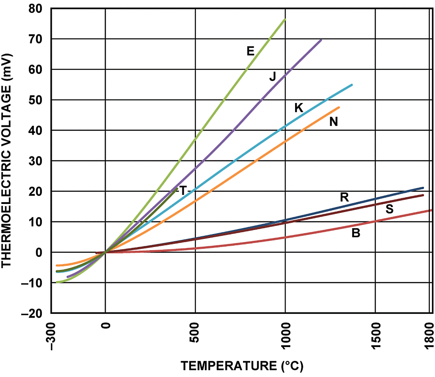
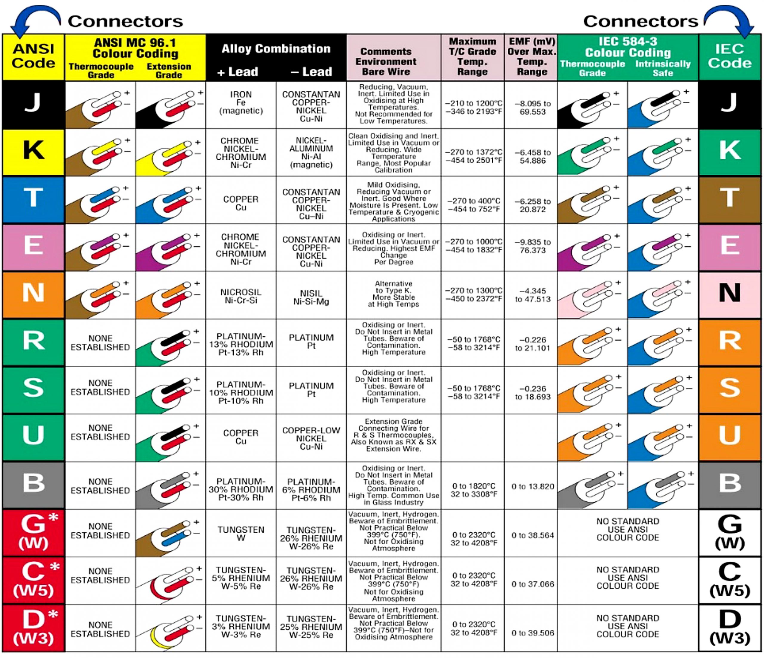
At the turn of the 20th century, there were more processes than just those in the glass and steel industries that would benefit from accurate and rapid temperature measurement. The use of noble metals, comparatively costly rare elements, began to give way to base metals and alloys, which were more economical and readily available in applications where the high temperatures were not extreme. Examples of noble metals include platinum, rhodium, gold, tungsten, and rhenium. Base metals are relatively inexpensive, and include common metals such as nickel, copper, iron, and chromium. In 1905, Albert Marsh invented Chromel, a nickel-chromium alloy. Names such as Hoskins Manufacturing and Harrison Alloys appeared. Type J, an iron and copper-nickel thermocouple, was the first base metal thermocouple type widely accepted. Over the years, other thermocouple types were developed and accepted. By the middle of the century, standardization was taking place regarding types with color coding for the positive and negative legs of the different types coming shortly thereafter. By this time also, much more was understood about the relationship between EMF and temperature, and the relationship could be expressed mathematically and predicted. (Figure 2)
Electromotive force or EMF is simply the electrical action produced by a non-electric source. The source can be chemical like a battery, mechanical as in a generator, or, in the case of a thermocouples or thermocouple wire, it is temperature related. A thermocouple is really a transducer that changes temperature differences into a small amount of voltage. This voltage is measured in millivolts. Theoretically, any two dissimilar metals will work and produce an EMF if they are in a closed loop; however, for the sake of accuracy, consistency, and predictability, the purity and choice of the compositions of the metals used is critical.
Common types of thermocouples
The most common types of thermocouples can be split into base metal and noble metal as mentioned previously. Base metal types are E, J, K, N, and T. These can be used in cryogenic applications and in temperatures up to 1,400°C, depending upon the type. Base metal thermocouple types are selected based on their EMF output or sensitivity, temperature range, and application environment. Noble metal types include Type B, R, S, C, D, and G. These are used in high-temperature environments over 1,400°C and up to 3,000°C for brief periods. Their expense and low sensitivity typically restrict their use to very high-temperature applications. Generally speaking, base metal thermocouples have higher sensitivity than noble metal thermocouples; however, they are limited to temperatures below 1,400°C. Noble metal thermocouples, especially platinum-based are generally the most stable, significantly more expensive, more suitable for elevated temperatures, and less sensitive, especially at lower temperatures.
Type E thermocouples have nickel-chromium and copper-nickel legs. Type E has a wide functional temperature range and the highest EMF per degree of any base metal thermocouple. It would be good for oxidizing atmospheres but would be vulnerable to sulfur attack. Type E would work well for cryogenic temperatures. It would be more stable than Type K.
Type J thermocouples have iron and copper-nickel legs. It has a narrower temperature range than Type K and would have a shorter life span at higher temperatures. Type J has a higher sensitivity than Type K, which it would be most often compared to. Type J is low cost; however, the iron leg is susceptible to oxidation.
Type K thermocouples have nickel-chromium and nickel-aluminum legs. The alloys make Type K more expensive than Type J. Type K has the widest application temperature range and performs better than Type J at higher temperatures. It would be suitable for oxidizing atmospheres because of the alloy composition. Type K is probably the most popular general-purpose thermocouple in use.
Type N thermocouples have nickel-chromium-silicon and nickel-silicon legs. It is a relative newcomer to thermocouple types and is considered an improvement over Type K. The temperature range of Type N would be similar to Type K; however, it would have better repeatability between 300°C and 500°C. Type N would be good in oxidizing environments and would have less drift than Type K. Type N is more expensive than Type K.
Type T thermocouples have copper and copper-nickel legs. It is a very stable thermocouple type and performs very well in cryogenic applications. The functional temperature range of Type T is narrow and should be limited to under 400°C. It performs extremely well from minus-200°C to 200°C, and it should function well in oxidizing atmospheres.
Types B, R, and S have legs that are platinum and platinum-rhodium-alloy based. They are expensive. These types are most suitable for high-temperature applications. They are the most stable thermocouple types but have low sensitivity. Because of their stability and repeatability, they are often used as calibration standards.
Types C, D, and G are tungsten-rhenium based. They were designed for use at extremely high temperatures in reduced atmosphere or vacuum environments. They are expensive, difficult to manufacture, fragile, and should not be used in the presence of oxygen above 260°C because of reaction rates that will cause them to be brittle.
Achieving desired EMF outputs
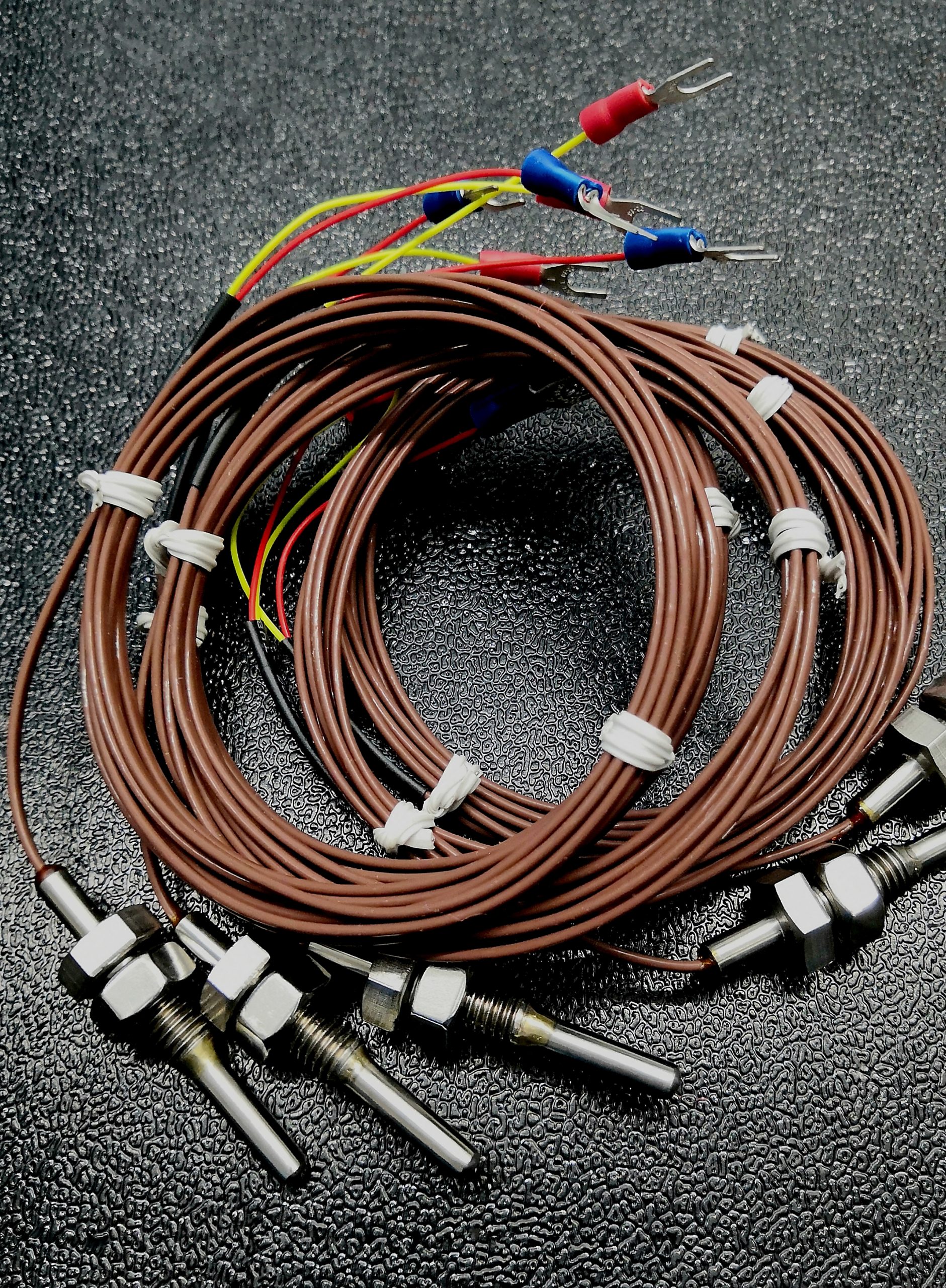
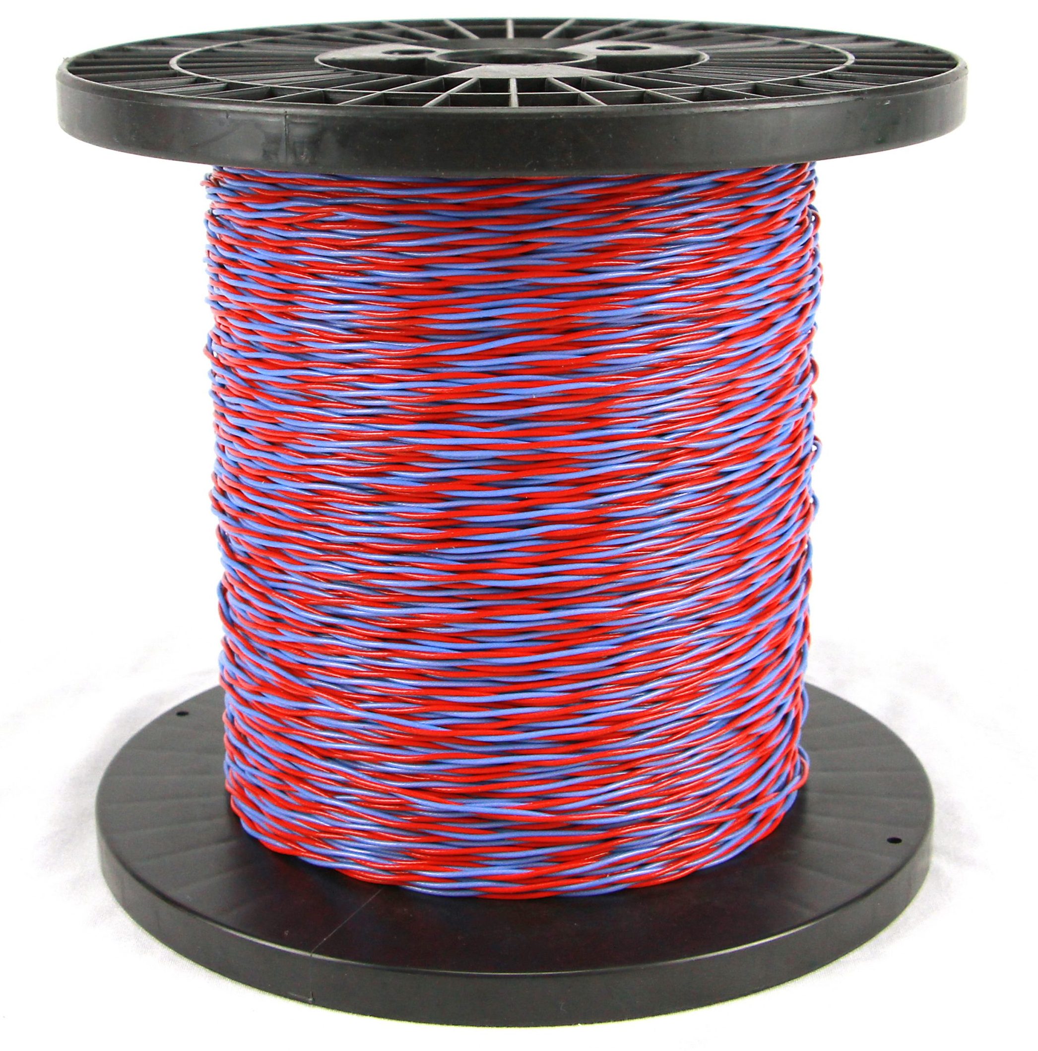
It has taken decades for thermocouple wire producers, the melter, to perfect the chemical composition of each thermoelement or leg to achieve the desired EMF outputs (Figure 3). The positive and negative legs of a thermocouple must work together predictably to produce accurate and reliable temperature measurements for the end user. Raw base and noble metal elements such as platinum, tungsten, chromium, nickel, iron, copper, manganese, and others are melted and combined in previously determined ratios or percentages to form the individual legs. These chemical recipes are relatively precise and aim for a desired EMF result.
The result of the melting of one leg and corresponding EMF data influences the melting of the opposing leg with the goal of maximizing accuracy. Within the melting process, there is room to adjust the melt or heat so the legs can be matched. ASTM E230 Standard Specification for Temperature-Electromotive Force Tables for Standardized Themocouples is the standard used to classify the accuracy of a thermocouple pair. The EMF data used to match the legs is recorded and typically posted on the thermoelement spool prior to sale. This enables the user to keep the pairs matched and provides traceability.
Matched pairs
It is important to understand the melter sells thermocouple legs in matched pairs. Selling in matched sets allows the producer to guarantee the total EMF output and if the pair meets a desired Limits of Error standard. There are two Limits of Error classifications to be concerned with: Special Limits of Error and Standard Limits of Error. These two Limits of Error apply to extension grade wire as well. While the melter uses time-proven and precise recipes for producing thermoelements, there are factors that can affect the results of a melt and, in turn, affect EMF output. Impurities in raw material, for example, can be an issue. Melting practices, the condition of the furnace, and even human error may have an impact. As a result, not all wire melted within a certain type will have exactly the same EMF output. The EMF tables within ASTM E230 help sort this out.
Accepted tolerances
In measurement systems, there are accepted tolerances, and temperature measurement with thermocouples is no exception. These Limits of Error are defined by ASTM E230. Simply the tolerance for Special Limits of Error is tighter or less forgiving than for Standard Limits of Error. The tables within ASTM E230 dictate what meets Special Limits of Error and what meets Standard Limits of Error. Calculations using the EMF data of the individual legs of a thermocouple are made in conjunction with the ASTM tables.
The EMF outputs for both legs are added to each at specific temperature points, for example 400°C. The total EMF for the positive and negative legs at that temperature point is then subtracted from the ASTM specified total EMF at that temperature point. That Delta is then divided by a millivolt factor specific for a type of thermocouple wire. Each thermocouple type will have its own designated millivolt factor. The quotient is then compared to the tolerances in the ASTM table for Special Limits of Error and Standard Limits of Error for that thermocouple type at those specific temperatures. If it falls within the plus-or-minus tolerance for Special Limits of Error, then the thermocouple will be classified as such. If not, then it will drop into the Standard Limits of Error Classification, assuming it meets those tolerances.
A cautionary part of this is that it is possible for a thermocouple to meet Special Limits of Error tolerances at one temperature but fall out at another. If the wire falls out anywhere, then it should not be classified as Special Limits of Error. The same would be true for Standard Limits of Error. If a thermocouple does not meet the standard at all calibration points, then it does not meet the standard.
Matching up unmatched pairs
It is possible to match up unmatched pairs of thermocouple legs, but care must be taken. The EMF data on spools can be an indicator that the two legs may produce a favorable result, but the data and calculations should be verified by actual lab calibration of the wires. Calibration results are often required by end users involved with critical processes in the heat treating and pharmaceutical industries, for example. Calibration can be performed by wire fabricators who purchase wire from the melter or by thermocouple sensor manufacturers.
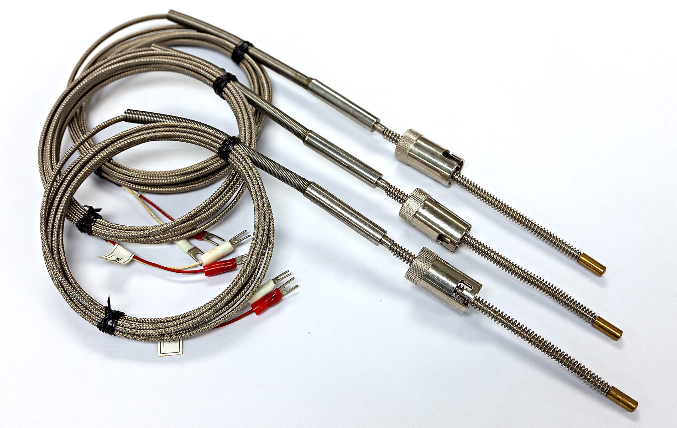
A well-equipped calibration lab will have three elements: It is necessary to have a temperature medium, a reference thermometer or standard, and a way to capture the outputs of the reference device and thermocouple being tested. The temperature medium can be, for example, liquid nitrogen for cryogenic calibration, an oil bath, or a dry block oven or tube furnace for elevated temperatures. Reference devices can be platinum-resistance thermometers or platinum-based thermocouples, which were mentioned earlier as being commonly used as standards in calibration because of their stability. The third element is a device for reading and recording the temperatures of the reference and the thermocouple under test at specific temperatures.
So equipped, a wire fabricator or sensor manufacturer can assure an end user that the thermocouple wire they are using is accurately interpreting the temperatures in their process.


 general practice for CQI-9 and AMS2750E")


