


Chromium was introduced as a potential alloying element for powder metallurgy (PM) steels in the 1990s. Since then, numerous chromium-containing alloy systems have been introduced and standardized in the North American market. While applications have been successful in using the benefits of these materials, the overall growth has been limited due to perceived concerns relating to the oxidation sensitivity of chromium-containing materials during sintering. In this study, test specimens were prepared from the FL-5108 and FL-5305 material systems and sintered in various commercial sintering furnaces located at North American PM-component manufacturers using their current sintering conditions. Results of the study show that most commercial sintering conditions in North America are adequate to achieve the expected mechanical properties and microstructures for these materials.
Introduction
As chromium is a carbide-stabilizing element, it is commonly used in wrought low-alloy steel production to provide improvement in hardness and strength over plain carbon steels [1]. Numerous, low-alloy steel compositions using chromium are available and well-documented on the benefits they provide with regards to strength, toughness, and hardenability. In concentrations above 11 percent with iron, chromium can provide stainless properties through the formation of an adherent chromium-rich oxide surface film. Stainless steel materials are one of the largest applications of chromium in wrought-steel metallurgy.
Chromium was first used by PM in the creation of stainless steel powders in the 1930s [2]. Initially, elemental powders were mixed to make the stainless steel compositions.
However, these mixes were quickly replaced via water atomization due to the long sintering times required to achieve chemical homogenization. Water-atomized stainless steel powders were introduced in the 1940s. Further research resulted in powder manufacturing improvements resulting in improved powder properties. This improvement allowed for the first major growth in PM stainless steel to happen in the 1980s with the adoption of antilock brake sensor rings manufactured by ferritic PM stainless steel [2]. Further adoption of stainless steel PM solutions followed soon after with exhaust flanges and sensor bosses.
The initial studies completed on how best to use chromium in PM low-alloy steel compositions followed a similar trend to PM stainless steels. Initial studies looked at using master alloys or ferroalloys containing chromium in combination with traditional low-alloy base irons to create new low-alloy steel compositions [3]. As the chromium was tied with other materials, typically high-temperature sintering was required in order to achieve sufficient diffusion of the chromium. In many cases, the time and temperature required did not allow for full homogenization to take place, so the full benefit of chromium was never realized. Attempts were also made using oil atomization to manufacture chromium alloys, although these materials did not reach full commercial benefit [4-5].
For the pre-alloying technique, alloying elements are added to the molten steel and stirred with argon prior to water atomization. Pre-alloying results in a homogenous distribution of alloying over each powder particle. Traditionally, pre-alloyed PM steels used molybdenum, nickel, and manganese in different levels to provide numerous alloying compositions. These alloying elements were chosen due to their impact on hardenability and the ability to sinter in a wide range of sintering atmospheres, particularly those containing high amounts of oxygen. With the advent of nitrogen/hydrogen sintering atmospheres and the resultant low dew points, elements that were more sensitive to oxygen were able to be explored for new alloys. Pre-alloyed chromium-containing alloying systems were introduced in the late 1990s as a new alloying family [6].
When the new alloys were introduced, instructions were given with regards to the requirements for the sintering atmosphere [6-10]. Thermodynamic calculations were made for the recently introduced alloys to determine the theoretical allowable partial pressures of oxygen in the sintering atmosphere for conventional sintering temperatures of 1,120 °C (2,050 °F). The focus on oxygen in the sintering atmosphere is important as the partial pressure of oxygen in the sintering atmosphere determines whether a metal is oxidized or if the metal oxide is reduced. This chemical reaction happens in accordance with Equation 1.
![]() After the de-lubrication step in sintering, the oxide layer requires removal in order to allow the particles to neck together, forming the strong bonds that will be the foundation for the final strength of the component. With oxygen-sensitive elements such as chromium, the partial pressure of oxygen must be low in order for the oxides to be sufficiently reduced. As dew point is more commonly used to monitor the sintering atmosphere, the oxygen-partial pressures were used to calculate the maximum allowable dew points for successful sintering of chromium containing materials [8]. Examples of the dew-point curves generated are shown in Figure 1.
After the de-lubrication step in sintering, the oxide layer requires removal in order to allow the particles to neck together, forming the strong bonds that will be the foundation for the final strength of the component. With oxygen-sensitive elements such as chromium, the partial pressure of oxygen must be low in order for the oxides to be sufficiently reduced. As dew point is more commonly used to monitor the sintering atmosphere, the oxygen-partial pressures were used to calculate the maximum allowable dew points for successful sintering of chromium containing materials [8]. Examples of the dew-point curves generated are shown in Figure 1.
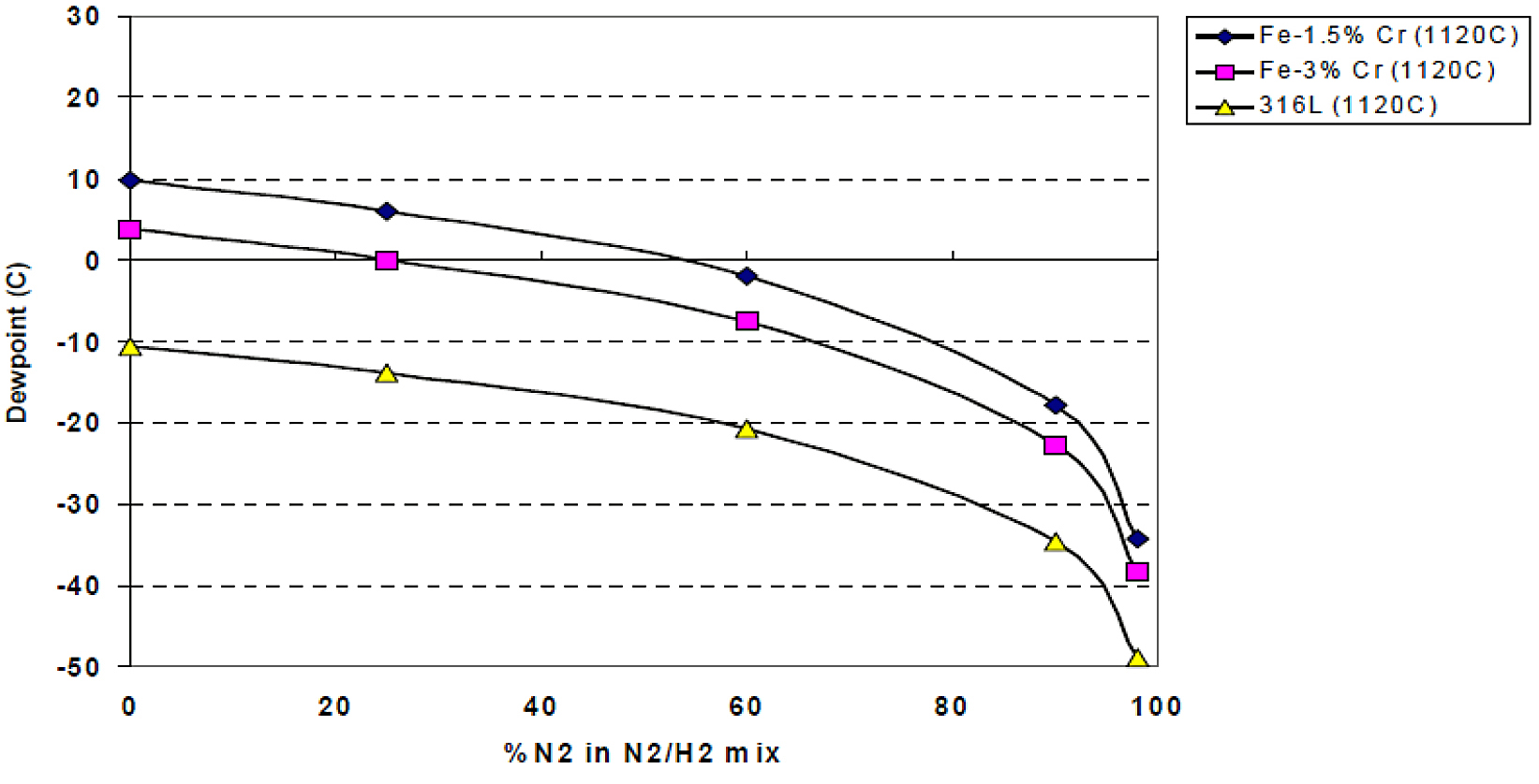
As hydrogen is the more expensive constituent of a nitrogen/hydrogen sintering atmosphere, most component manufacturers use just enough during sintering to accomplish the oxide reduction process. With the pre-alloyed chromium materials, stricter requirements for dew point are required as the hydrogen level is reduced as shown in Figure 1. As much focus was put on this, the initial acceptance of these materials was slow, although many components were successfully realized [11-12]. One of the main reasons for the slow acceptance of these pre-alloyed chromium materials was the reported controls required on sintering atmosphere.
As the majority of sintering atmospheres in North America used a synthetic blend of pure nitrogen and hydrogen, a blind-sintering study was conducted to assess the current sintering situation in North America. Five component manufacturers who are known to sinter in a nitrogen/hydrogen atmosphere agreed to participate in the blind study. These locations would be compared against two locations with many years of experience in sintering chromium-containing materials. The commercial-sintering locations were not made aware of the composition of the bars they were sintering other than they were low-alloyed PM steels. Results show the chromium materials were able to be sintered easily and minimum properties as stated in MPIF Standard 35 were met for all but one location [13].
Experimental procedure
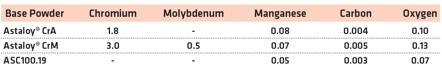
For this study, two pre-alloyed chromium powders were evaluated in MPIF standard compositions [13]. A plain, iron-based copper steel was also evaluated at the same time as a reference material. The chemistries of the base powders used for the study are shown in Table 1.
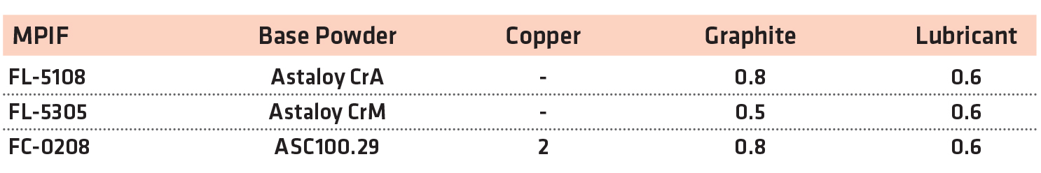
From these base powders, premixes were manufactured using synthetic graphite (F-10, Imerys) and lubricant (Intralube® E, Höganäs). To manufacture the copper steel, water-atomized copper powder was used (Cu-165, Royal Metal Powders). The mix compositions are shown in Table 2.
For each mix, flat, un-machined tensile specimens and rectangular impact specimens were compacted to a green density of 6.9 g/cm3[14].
As the purpose of this study was to evaluate the response of the chromium materials to various sintering conditions, a number of locations were used to conduct the sintering. Two Höganäs Technical Centers (North America and Asia) sintered bars as a baseline for the study. Five PM component manufacturers were sent green specimens to perform sintering at their standard conditions in production mesh-belt furnaces. They were not made aware of the exact composition of the bars. The instructions for sintering were to process the bars at their standard manufacturing conditions and report what conditions were used. As they were not aware of the presence of chromium in the alloys, no adjustments were made to their furnaces to accommodate the presence of chromium in two of the material systems. For confidentiality reasons, the component manufacturers have been given a letter code. The sintering conditions used in this study are summarized in Table 3.
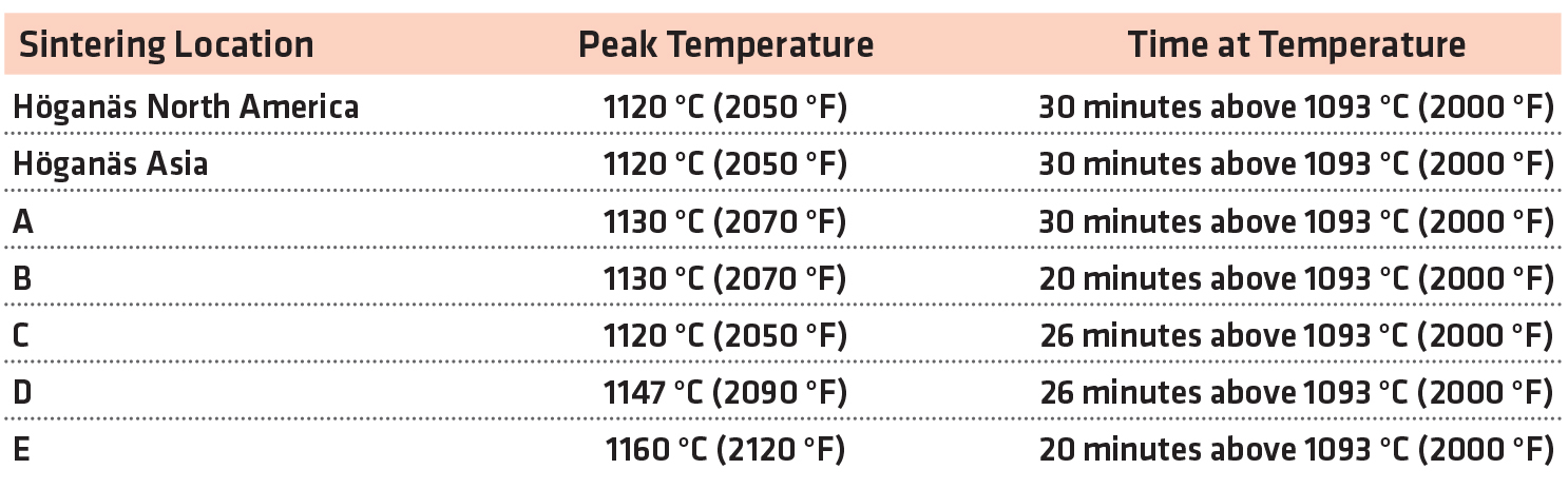
All of the atmospheres were predominately nitrogen with a small amount of hydrogen (3-10 v/o). Standard cooling speeds were used in all cases.
After sintering, the specimens were evaluated for tensile and impact properties in accordance with ASTM E8 and E23 respectively [15-16]. Apparent hardness, micro-indentation hardness, and sintered-density measurements were done in accordance with MPIF standards [14]. The carbon and oxygen levels were determined on the impact specimens in accordance with ASTM E1019 [17]. Microstructure determination was made using light-optical microscopy.
Results
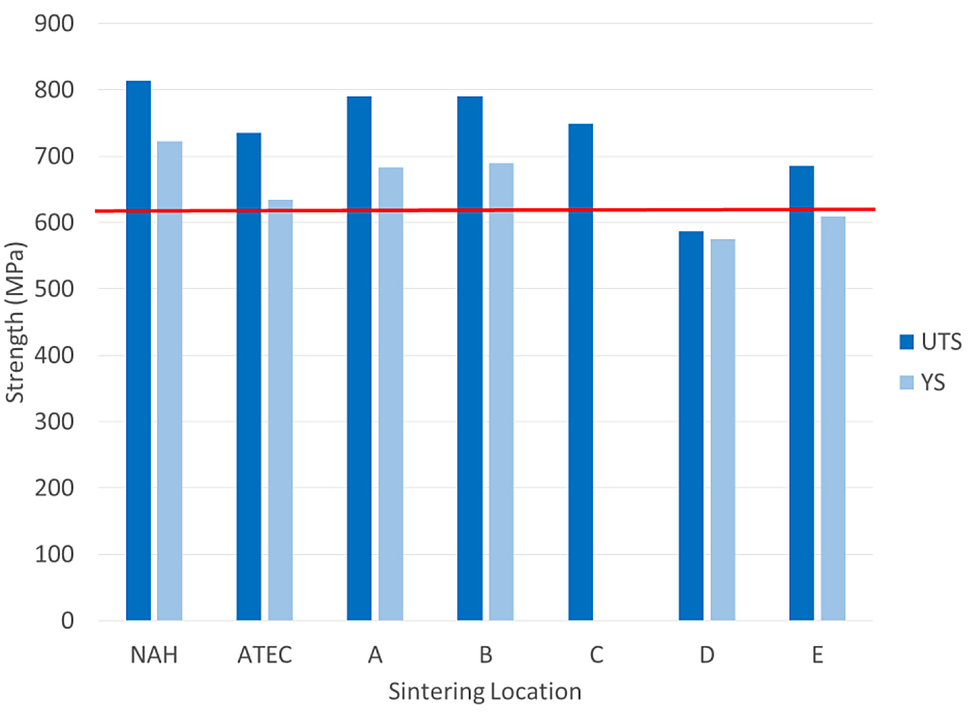
The tensile results for the FC-0208 material are shown in Figure 2.
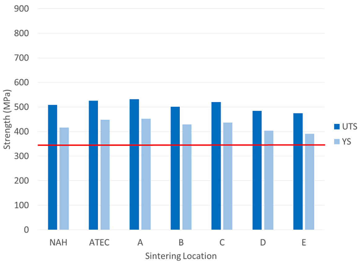
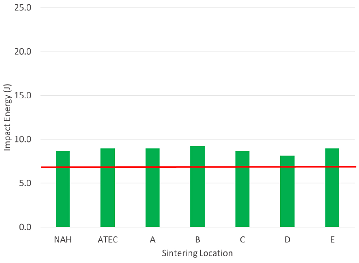
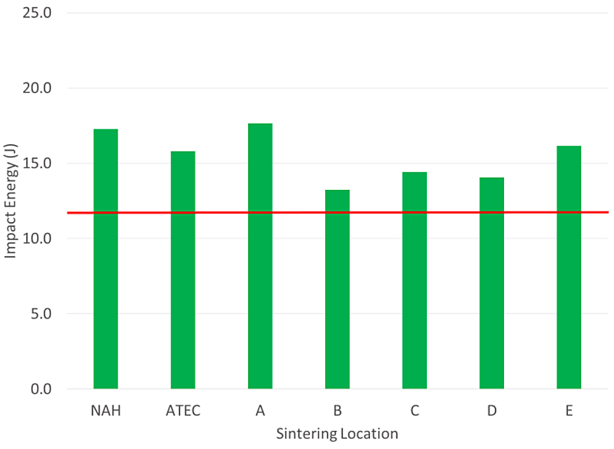
The tensile properties for the FC-0208 material all met the MPIF minimum for yield strength. All locations, except for location E, were above 400 MPa for yield strength. The impact results for the FC-0208 are shown in Figure 3.
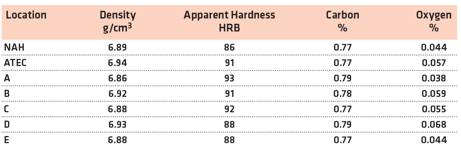
For the FC-0208, all of the lab results met the typical value for impact energy at this density level. All of the labs were similar in the impact value. The results for density, hardness and chemistry of the FC-0208 are shown in Table 4.
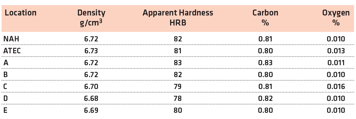
The physical and chemical properties of the FC-0208 materials were similar for all sintering locations.
The tensile results for the FL-5108 are shown in Figure 4.
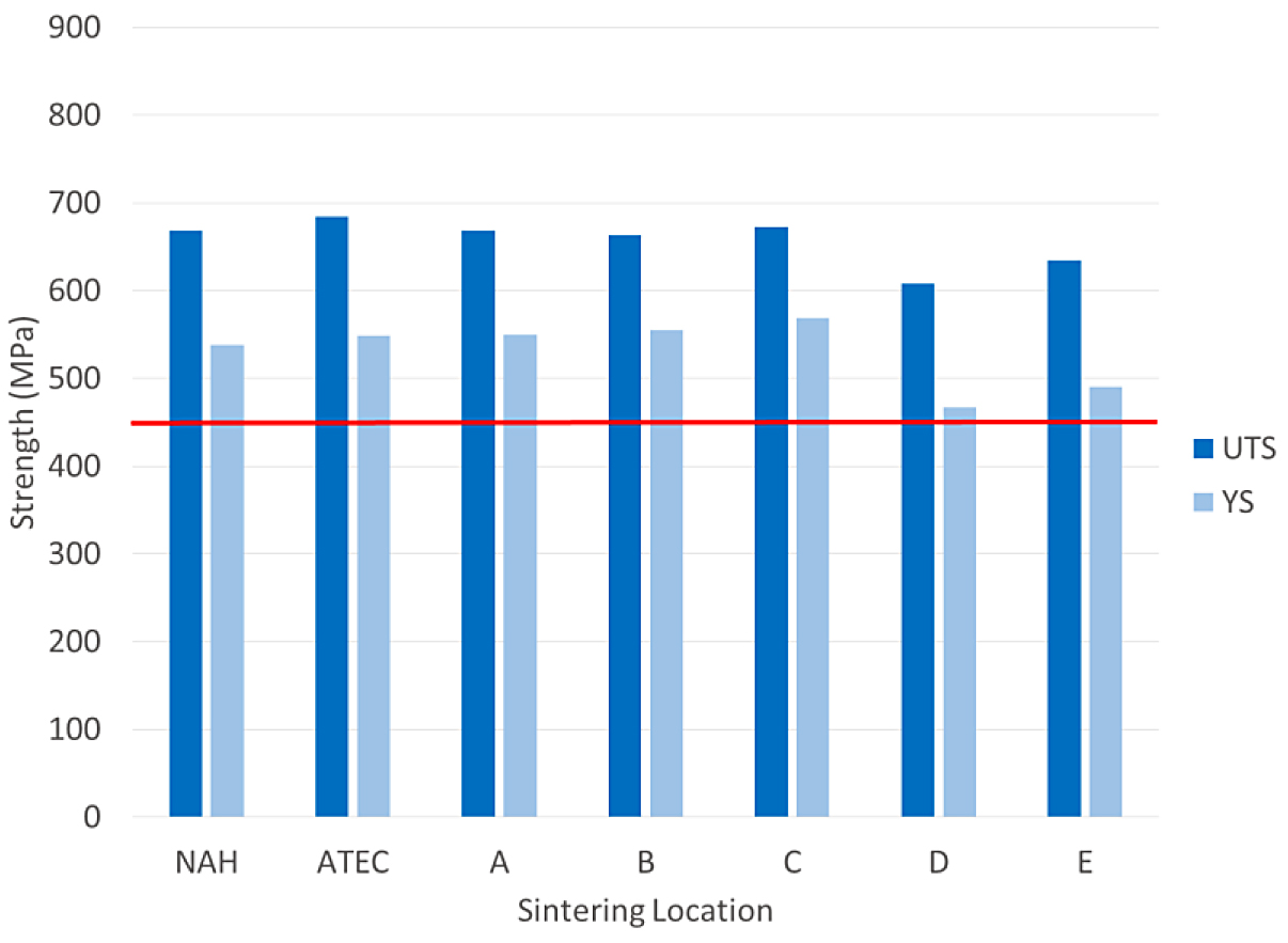
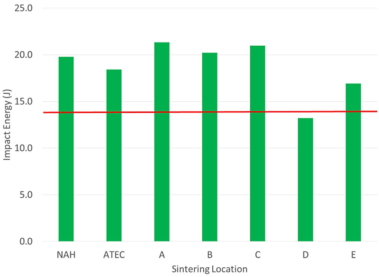
The tensile results of the FL-5108 all met the MPIF minimum for yield strength. In this case, location D was nearest to the minimum yield strength requirement. The impact results for the FL- 5108 are shown in Figure 5.
All of the sintering locations were above the typical value for impact energy. The physical and chemical results of the FL-5108 materials are shown in Table 5.
The density and hardness levels were similar between the sintering locations. As expected, the oxygen levels were elevated compared to the FC-0208. However, all of the values were typical for this material system and sintering conditions.
The tensile results for the FL-5305 are shown in Figure 6.
The tensile results for the FL-5305 were more mixed compared to the other materials. There were three locations that did not meet the minimum yield-strength requirement. The tensile bars sintered at location C did not yield and no values were measured. Location E was just short of the minimum required value for this material. The impact energy results for the FL-5305 material are shown in Figure 7.
For the FL-5305, one sintering location did not meet the MPIF typical value for impact energy (Location D). The other locations were well above the typical value stated in MPIF Standard 35.
The physical and chemical properties for the FL-5305 are shown in Table 6.
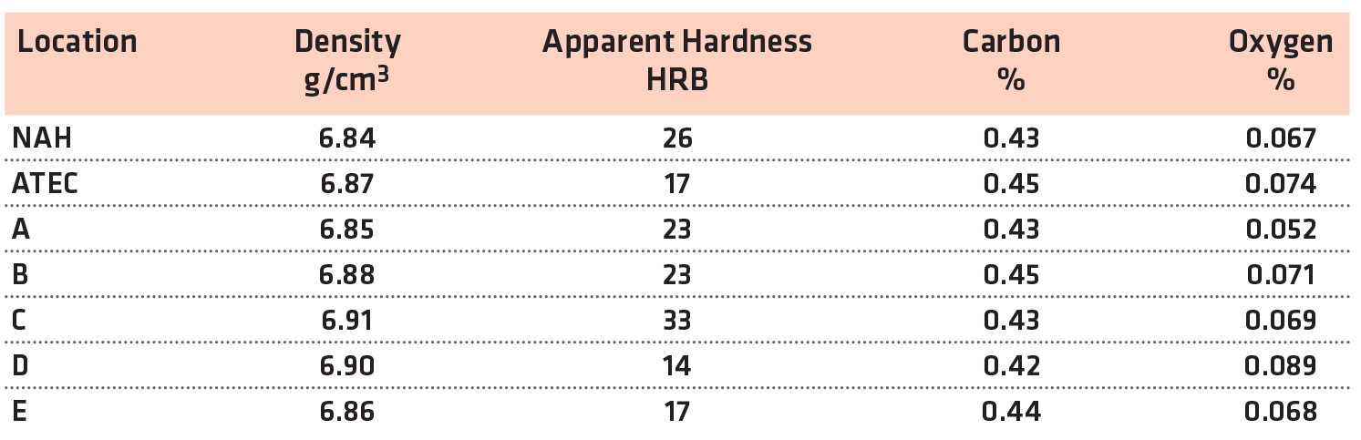
The apparent hardness measurements showed a large range between the sintering locations. The apparent hardness ranged from a low of 14 HRC to a high of 33 HRC. All of the carbon levels were similar. The oxygen levels after sintering were higher than the FL-5108 as expected but within the typical range for this material and sintering conditions.
Discussion
Each of the material groups was evaluated for variation on the ultimate tensile strength within the group and then compared. The average strength results, the overall variation, and the coefficient of variation for each material group are shown in Table 7. There were two statistical outliers in the FL-5305 data set and were removed for the data presented in Table 7 and Figures 8 and 9.
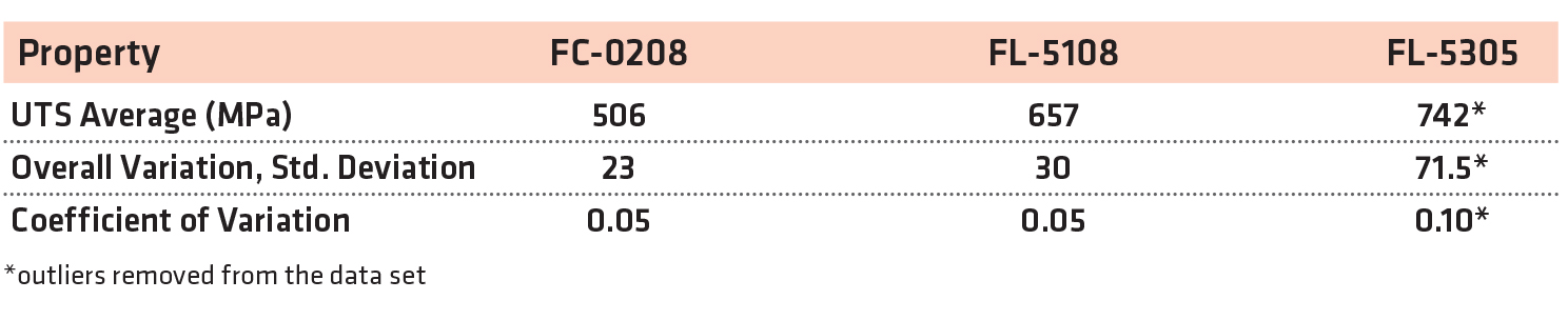
Calculation of the overall variation and the coefficient of variation found the FL-5305 to have higher variation compared to the FC-0208 and FL-5108. The FL-5305 data contained more than twice the variation compared to the other two materials even with the statistical outliers removed.
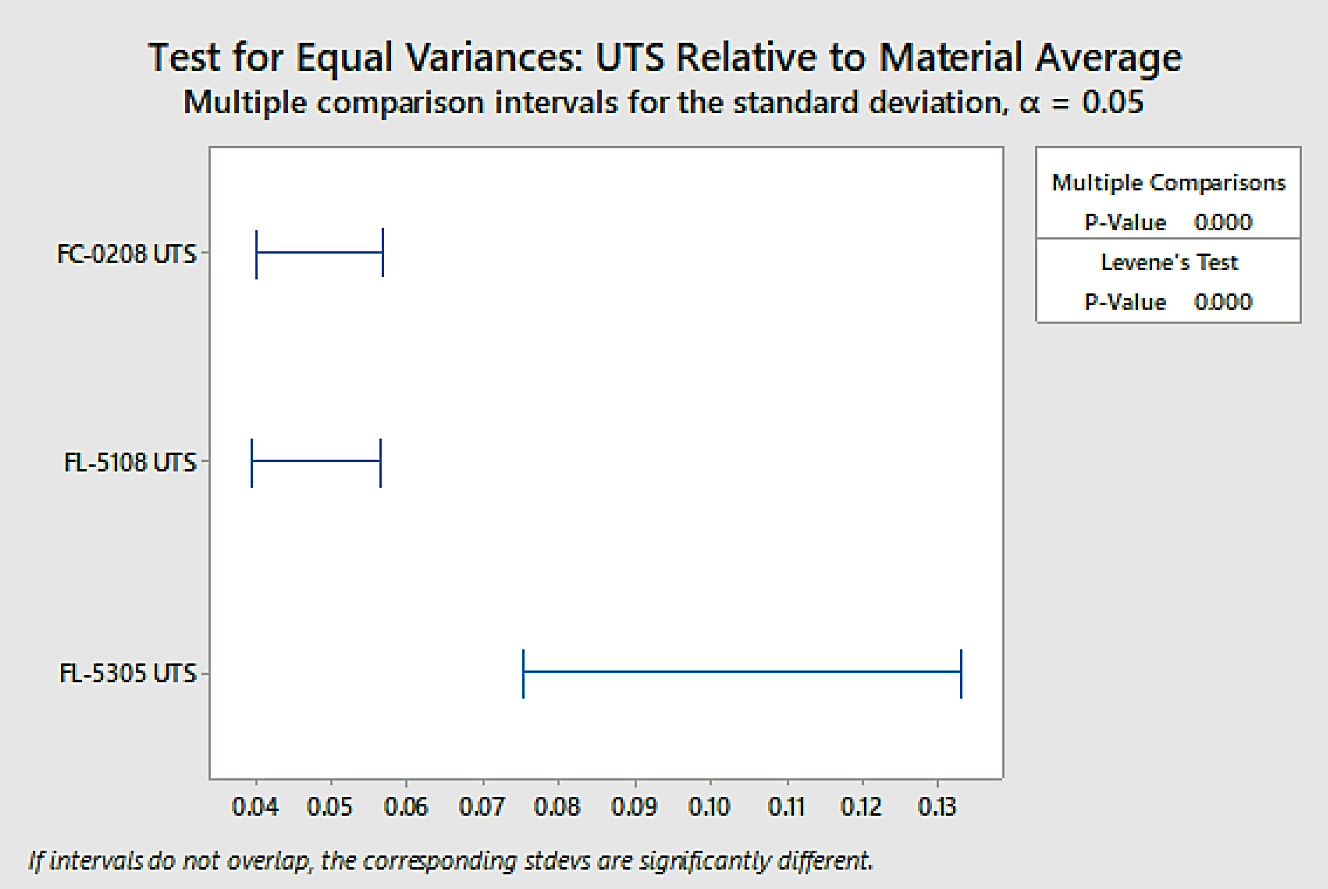
Analysis was also conducted for overall variation to determine if the difference in variation between material groups was statistically significant through test for equal variances. The data is shown in Figure 8.
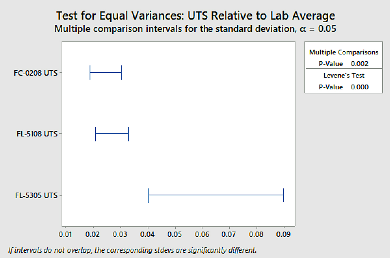
The difference in overall variation between the FL-5305 and the other two material groups was found to be statistically significant using a confidence level of 95 percent. To determine variation within sinter locations, a test for equal variance was again performed. Those results are shown in Figure 9.
The difference within sinter location variation between the FL-5305 and the other two material groups was found to be statistically significant using a confidence level of 95 percent. There was no statistical difference observed between the FC-0208 and the FL-5108 material groups within sinter location variation as their confidence intervals overlap using a 95-percent confidence level. The statistics confirm what was easily observed through a quick glance at the strength data.
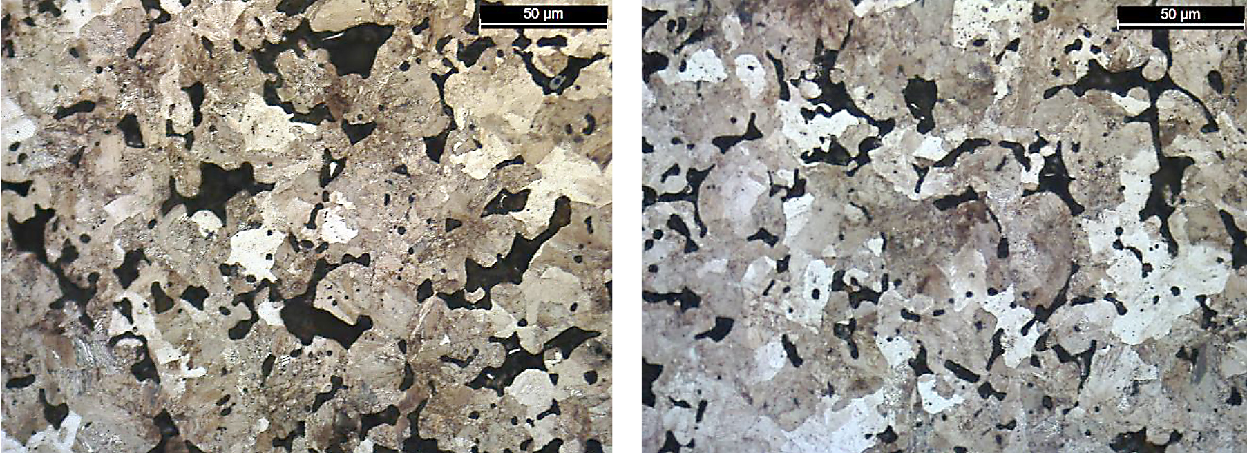
Along with the ultimate tensile strength values, the apparent hardness values of the FL-5305 also had a wide range even though the density and carbon values were similar. As expected, the hardness values directly related to the resultant microstructure. For these bars, the higher apparent hardness values correlated directly to the amount of martensite in the material. Photomicrographs for the lowest strength (Location D, 587 MPa) and highest strength (North American Höganäs, 794 MPa) sintering locations are shown in Figure 10.
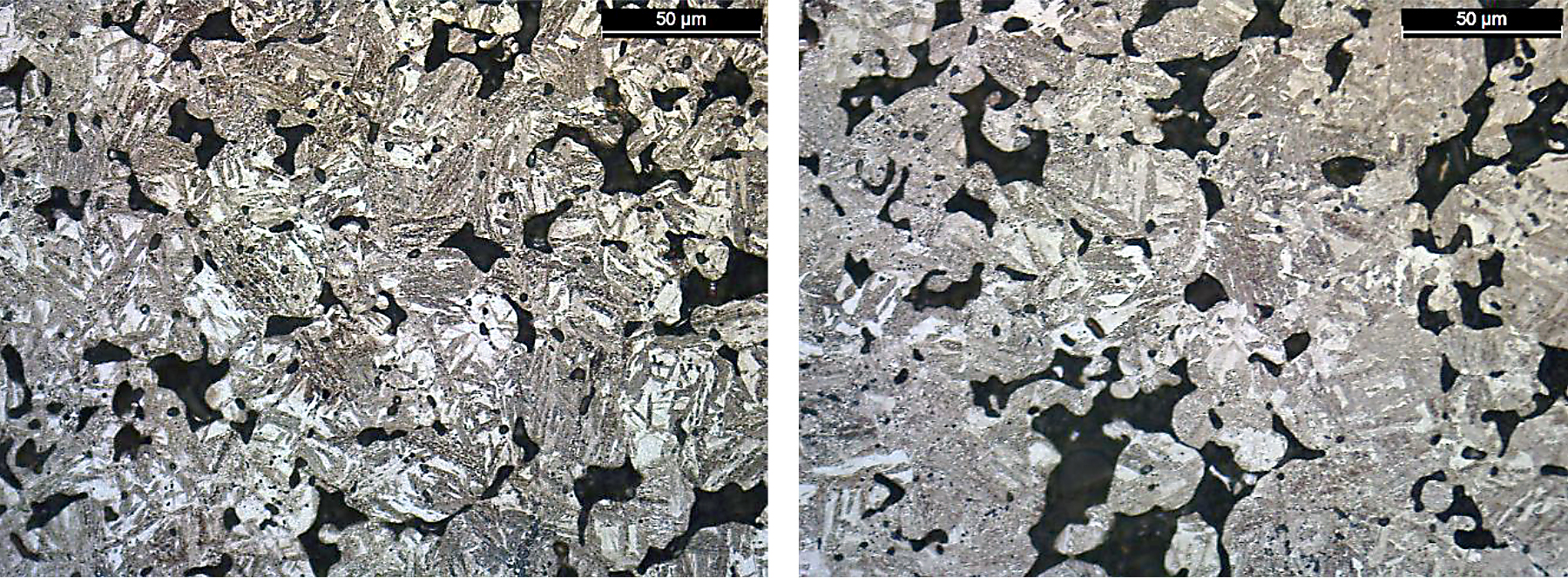
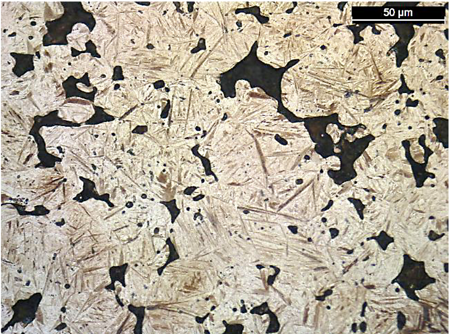
There was a difference in the amount of martensite present for these two sintering locations. For location D, the amount of martensite was significantly lower compared to the bars sintered at North American Höganäs. When using color segmentation analysis to determine the phase percentage, the amount of martensite was found to be 5 percent for location D compared to 20 percent for North American Höganäs. As Location C did not yield during tensile testing, these bars were also evaluated for microstructure. A photomicrograph for this material is shown in Figure 11.
Here, a predominately martensitic microstructure was observed. While this resulted in the highest apparent hardness value for the different sintering locations, the ultimate strength was only fourth highest between the labs. This is likely due to the dog-bone tensile specimen used.
MPIF Std. 10 indicates that martensitic materials tested using this specimen configuration typically result in lower values than a machined round specimen. The tensile bars were also not tempered after sintering, which also plays a role in the lower tensile results for Location C [18].
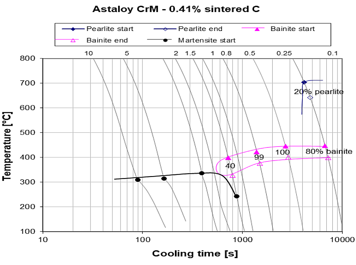
From the microstructure analysis, it was found that Location C and Höganäs North America had higher cooling rates during sintering compared to the other locations. Evaluating the microstructures of Location C and Höganäs North America against the continuous cooling transformation diagram for this material system and carbon level (Figure 12), the microstructure indicates location C had a cooling rate of approximately 1°C/s, Höganäs North America was approximately 0.8°C/s and Location D was 0.5°C/s.
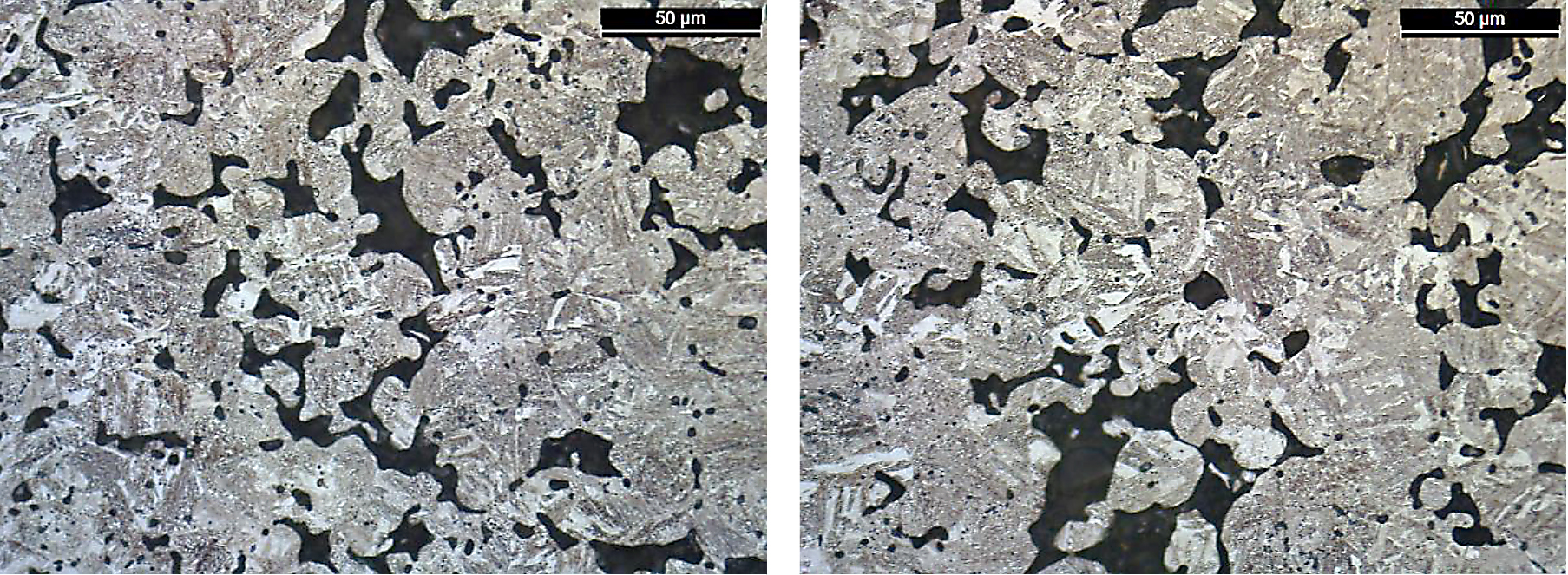
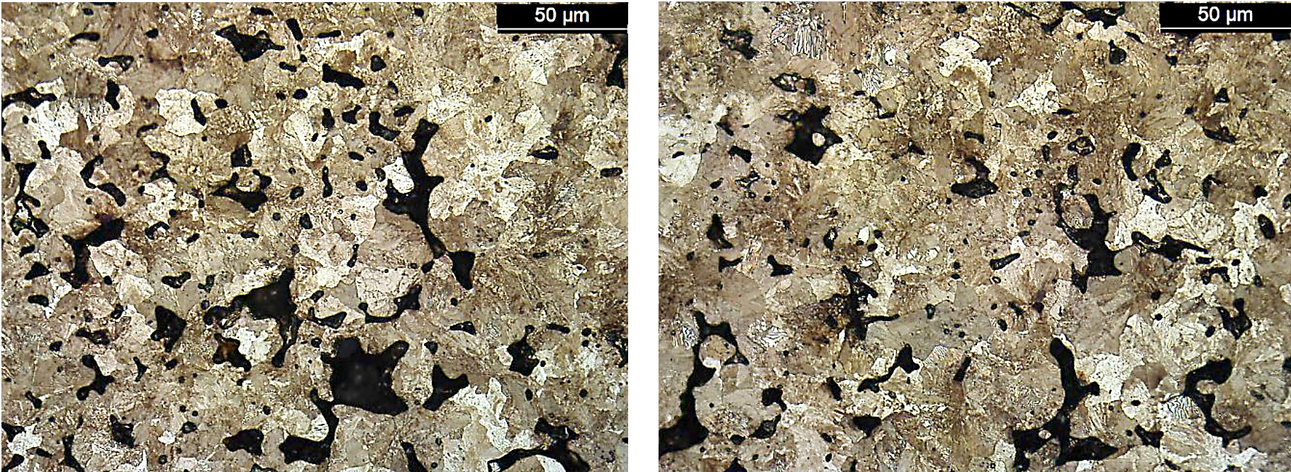
Location A, which had a high-tensile strength of 789 MPa to location D, did not show a large difference in microstructure. Both materials are shown in Figure 13.
As the amount of martensite was similar in each location, microstructure phase formation doesn’t entirely explain why location D had the lowest ultimate tensile strength values. The sintered oxygen levels (Table 6), which in turn relate to sintering connection formation, were also highest for location D.
The microstructure sensitivity for the FL-5305 is an order of magnitude higher compared to the other two materials evaluated. Both the FC-0208 and FL-5108 exhibited a pearlitic microstructure, and no large differences were observed between the highest and lowest strength sintering locations. Photomicrographs for these material systems are shown in Figures 14 and 15.
For the FL-5108, again location D had the lowest strength results and highest sintered oxygen values. However, the values were in line with the other sintering location as shown through the variation analysis of the results.
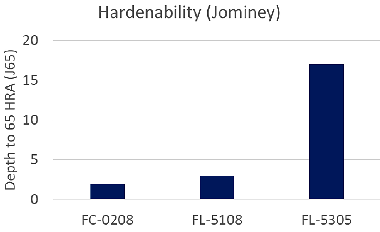
The FC-0208 and FL-5108 were both very similar in the variation-in-strength results and microstructure. They are also very similar in hardenability as documented in MPIF Std 35. The FL-5108 value isn’t listed; however, a similar alloy (FL-5208) was used for comparison understanding it would be slightly higher due to the addition of molybdenum. The comparison of hardenability is shown in Figure 16.
Conclusions
From this study, it was shown that pre-alloyed chromium steels could be conventionally sintered under standard industry conditions present today. Without special consideration for the atmosphere, properties achieved met what is required by industry standards. The lower chromium containing material (FL-5108) was comparable for strength variation with the PM industry’s most common material (FC-0208). More variation was observed between the sintering locations when sintering the higher chromium containing FL-5305. As this material has higher hardenability, it is more susceptible to cooling rate differences. Comparison on the microstructure between the low- and high-strength sintering locations found differences in the microstructure formed. In order to achieve the as-sintered properties listed in MPIF Standard 35, care should be taken to ensure the proper cooling rate is being used.
Acknowledgements
The authors would like to acknowledge the component manufacturers who participated in this sintering study. This study would not have been possible without their efforts to sinter the test specimens. The authors would also like to thank Christopher Malec of North American Höganäs for his assistance in the statistical analysis of the strength data.
References
- G. Totten and M. Howes, Steel Heat Treatment Handbook, First Edition, 1997, Marcel Dekker, New York, NY.
- E. Klar, P. Samal, Powder Metallurgy Stainless Steels, First Edition, 2007, ASM International, Materials Park, OH.
- D.J. Schaeffler, A. Lawley, R.J. Causton, “Low Carbon P/M Alloy Steels”, Advances in Powder Metallurgy & Particulate Materials, compiled by J.M. Capus and R.M. German, Metal Powders Industries Federation, Princeton, NJ, Vol. 5, p. 93, 1992.
- M. Ichadate, et al, “Sintering of Oil Atomized Low Alloy Steel Powders”, Horizons on Powder Metallurgy, Part 1, p. 57-60, 1986.
- I. Karasuno, “Some Properties of Oil Atomized Low Alloy Steel Powders Containing Chromium”, Horizons on Powder Metallurgy, Part 1, p. 53-56, 1986.
- C. Lindberg, “Mechanical Properties of a Water Atmized Fe-Cr-Mo Powder and How to Sinter It”, Advances in Powder Metallurgy & Particulate Materials, compiled by C.L. Rose and M. H. Thibodeau, Metal Powders Industries Federation, Princeton, NJ, Vol. 7, p. 229, 1999.
- B. Lindqvist, “Chromium Alloyed PM Steels – A New Powder Generation”, EuroPM 2001, European Powder Metallurgy Association, Vol. 1, p.13, 2001.
- B. Lindqvist and K. Kanno, “Considerations when Sintering Oxidation Sensitive PM Steels”, Advances in Powder Metallurgy & Particulate Materials, compiled by V. Arnhold, C.L. Chu, W. Jandeska, and H.I. Sanderow , Metal Powders Industries Federation, Princeton, NJ, Part 13, p. 278, 2002.
- R. Frykholm, P. Johansson, O. Bergman, “Considerations when Sintering Chromium- Alloyed PM Steels”, Sintering 2005, Grenoble, France.
- O. Bergman, B. Lindqvist, S. Bengtsson, “Influence of Sintering Parameters on the Mechanical Performance of PM Steels Prealloyed with Chromium”, PM 2006, Busan Korea.
- I. Howe, T. Haberberger and R. Cerini, “Composite Assembled Cam Shafts”, SAE Small Engine Tech Conference, Society of Automotive Engineers, Detroit, MI, 2008.
- D. Milligan, I. Hower, T. Haberberger and R. Cerini, “Lean Cr Containing PM Materials for Optimized Cost Performance”, SAE Small Engine Tech Conference, Society of Automotive Engineers, Detroit, MI, 2008.
- MPIF Standard 35, Material Standard for PM Structural Parts, 2018 Edition, Metal Powder Industries Federation, Princeton, NJ.
- Standard Test Methods for Metal Powders and Powder Metallurgy Products, 2016 Edition, Metal Powder Industries Federation, Princeton, NJ.
- ASTM International Standard E 8-16, Standard Test Method of Tension Testing of Metallic Materials.
- ASTM International Standard E 23-16, Standard Test Methods for Notched Bar Impact Testing of Metallic Materials.
- ASTM International Standard E 1019-11, Standard Test Method for Determination of Carbon, Sulfur, Nitrogen, and Oxygen in Steel, Iron, Nickel, and Cobalt Alloys by Various Combustion and Fusion Techniques.
- R. Warzel III and A. Neilan, “Effect of Composition and Processing on the Precision of Sinter Hardening Powder Metal (PM) Steels”, Advances in Powder Metallurgy & Particulate Materials, compiled by D. Christopherson & R.M. Gasior, Metal Powder Industries Federation, Princeton, NJ, 2013, part 5, pp. 62-73.
- Höganäs PM School Handbook, Metallography – Handbook For Sintered Components, 2015, Höganäs AB, Höganäs Sweden.
This paper was originally presented at POWDERMET2019, Phoenix, Arizona, and is included in the Advances in Powder Metallurgy & Particulate Materials — 2019, Metal Powder Industries Federation, 105 College Road East, Princeton, NJ 08540-0669.


 general practice for CQI-9 and AMS2750E")


