


Carbon/carbon and graphite materials are used in a variety of applications throughout the high temperature furnace industry. Entire vacuum hot zones are manufactured from these materials as well as individual components such as insulation, lining materials, nozzles, fasteners and hearth supports. Fixtures and grids are also commonly manufactured from these materials and can offer a variety of benefits to the heat1treating industry. These fixtures are specifically designed to allow for higher processing temperatures, increased part loading, increased production rates (via shorter cycle times), energy savings and lower overall cycle costs.1 In all of these areas, carbon/carbon composite materials offer unique technical advantages over other materials: higher processing temperatures; increased part loading; increased production rates; energy savings; and lower overall cycle costs.
Carbon/Carbon Composite Basics
Carbon/carbon composite (C/C) material consists of two primary components, carbon fibers and a carbon matrix (or binder). Carbon fibers are extremely thin strands of carbon atoms, typically 0.005 mm–0.010 mm (0.0002”–0.0004”) in diameter. They are interlaced in such a way as to provide mechanical strength, stiffness, and thermal conductivity. The carbon matrix that encases them allows for uniform weight transfer and chemical resistance to attack. Mechanical and physical properties are dependent on whether they are measured parallel or perpendicular to the surface and must be considered carefully when evaluating the quality of a composite material.
Carbon/carbon composite material has low thermal mass, high strength-to-weight ratio at temperature and negligible thermal deformation creating favorable net/tare load weight ratios when used for fixtures and grids. This allows for rapid heating and cooling rates, heavy part loading, and improvements in part distortion. C/C also has excellent fatigue resistance minimizing issues with crack propagation. Various manufacturers offer a variety of sizes, shapes, and grades. Purity levels in the range of 300 ppm total impurities are acceptable for general purpose heat treating with specialty applications available to as low as 10 ppm. The material can be supplied as fully densified or non-densified depending on the application.
Choices for Fixtures and Grids (UniGrid® or Press-Fit)
Two primary types of fixtures are used in the heat treatment industry: press fit grid style fixtures and single plate fixtures. Carbon/carbon fixture design is extremely important in determining which type of fixture style to use. Experience has shown that it is important to first identify the “worst case support scenario” for any fixture application during the initial product selection and subsequent engineering design phase. Unlike alloy fixtures that bend when over loaded, C/C fixtures break if they exceed their designated weight threshold.
Press-Fit Grid System
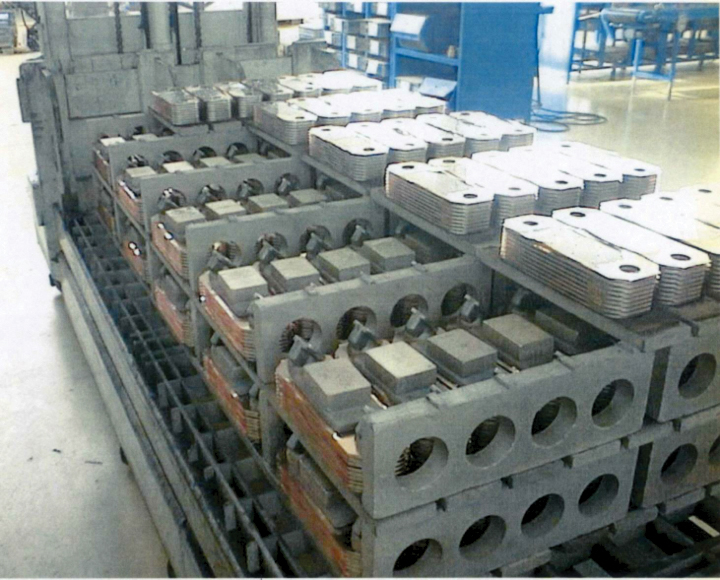
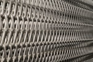
Press-fit grid fixtures (Figure 1) are made up of plate material. The plate material is cut into strips of various lengths, widths and thicknesses and press fit together to form a strong interlocking grid. These fixtures can be designed to carry heavy loads for applications such as high temperature brazing of heat exchangers (Figure 2). In this example the load weight is 3000 kg (6615 lbs.) This type of fixture is typically custom designed for each application and as such can be offered in a wide variety of furnaces, applications and load configurations.
Single Plate Grid System
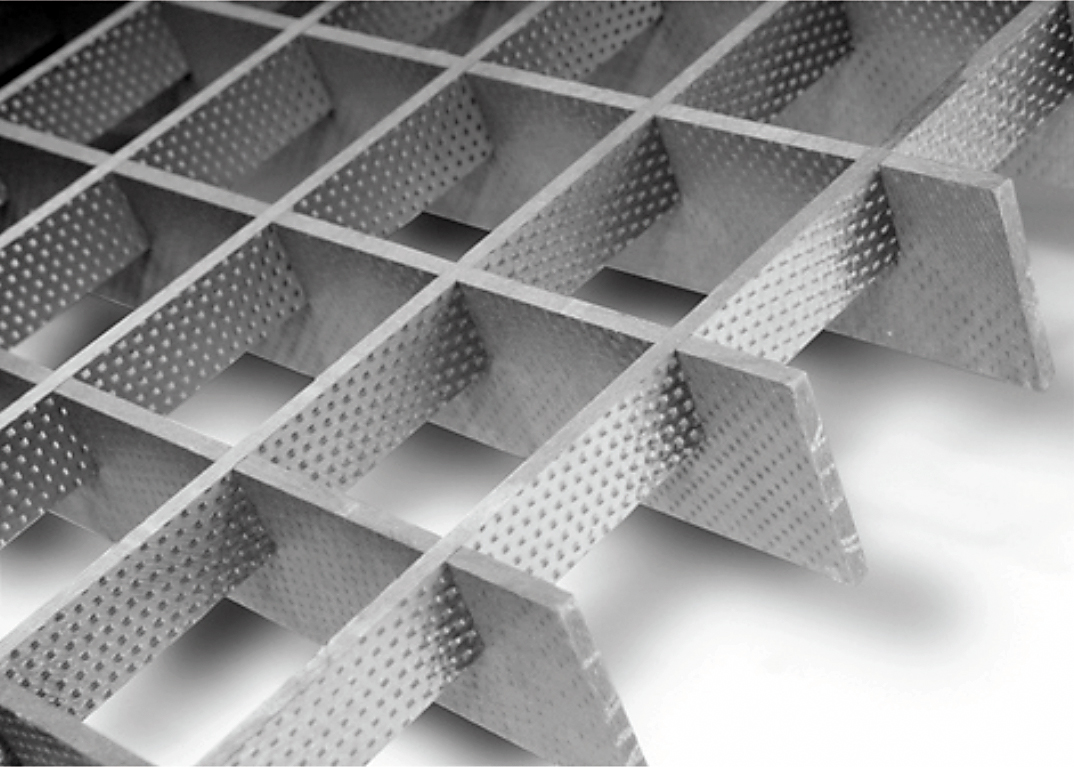
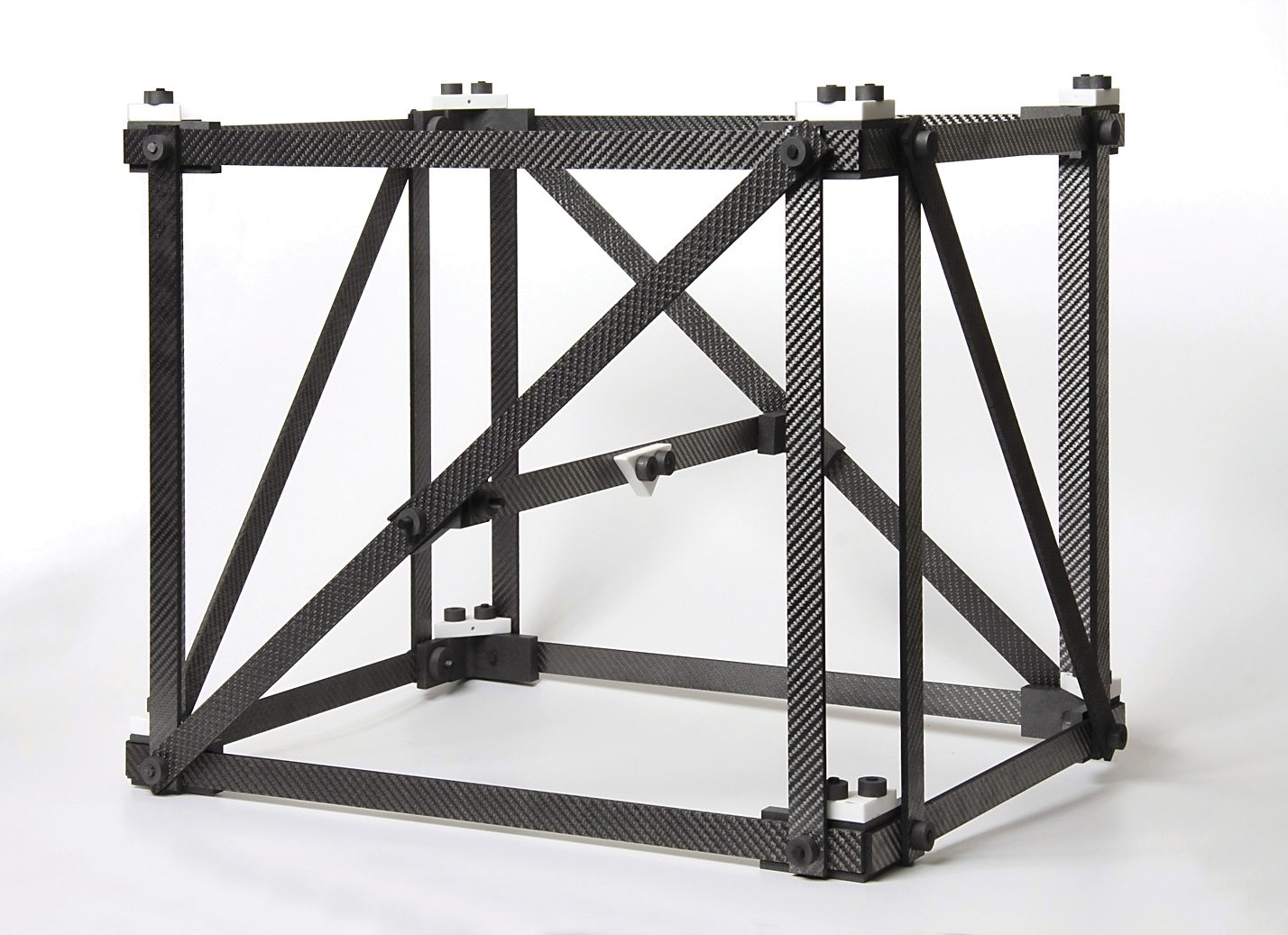
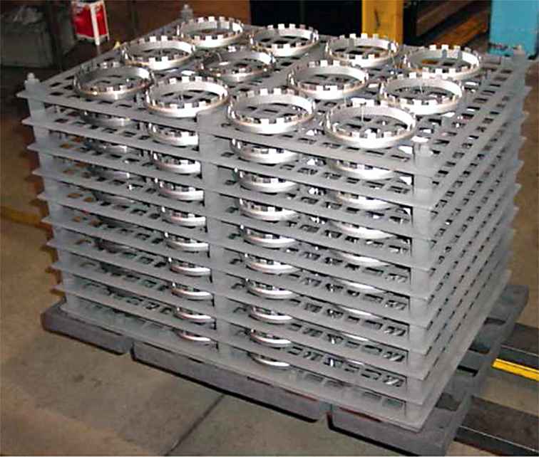
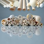
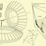
The UniGrid® (Figure 3) is an example of a single plate style grid system and differs from press fit fixtures. Each grid is made from a single unidirectional cord of carbon fiber that is wound into preforms and molded into its final configuration. Since there is no overlapping of the carbon/carbon cord, the fibers are stiffer and can support even heavy loads at a fraction of the thickness of press fit grid assemblies. The reduction in layer thickness can allow for additional layers to be added into a furnace load. This translates into increased throughput with every furnace cycle and lower power consumption.

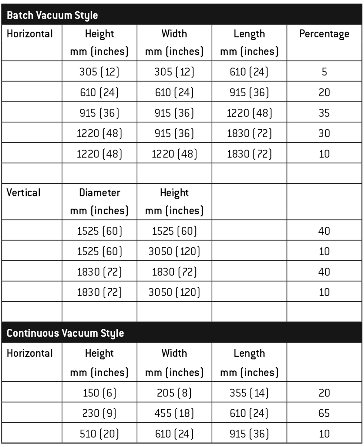
The UniGrid® comes in two configurations and rather than being cut from a plate, it is a molded-to-shape product. The grid, like most C/C fixtures, is designed as a modular, stackable system that can be configured to fit into most any standard furnace size (Table 1). It is currently being used in applications such as honeycomb brazing of aerospace seal rings, turbine blade brazing and carburizing of automotive transmission gears, to name a few. Depending on the process and fixture configuration, loads can vary from 1 kg (2.2 lbs.) to 100 kg (220 lbs.) or more per layer.
Additional Applications for Carbon/Carbon Fixtures
Depending on the temperature and application, carbon/carbon fixtures may work well in conjunction with alloy components. Combining both materials in a fixture can be favorable using the strengths of both materials while minimizing the weaknesses of each.
Multi-purpose fixtures lend themselves to the aerospace and automotive industries (with high volumes of similar parts to be run) but are also used in medical, small motor, commercial heat treat operations, and heavy industrial industries.
Strengthening Mechanism for C/C Composite Materials (K value)
Carbon fiber is manufactured by converting synthetic fibers (polyacrylonitrile or PAN for short) into carbon through the process of pyrolysis (that is, the thermochemical decomposition of an organic material at elevated temperature in the absence of oxygen). The result of this irreversible process is a change in both the chemical composition and physical phases of the resultant material. This process causes the carbon atoms to bond microscopically in crystalline form. It is the tight crystal alignment of these atoms that gives the carbon fiber its high tensile strength.
When choosing a carbon fiber plate for a given application, there are various types of carbon fiber cloth used in the manufacture of the plate material. Many of these materials are made from laminating layers of woven (so-called long fiber) cloth sheets together in a resin matrix that will also be converted to carbon during its processing. The various woven cloth materials have a “K” value associated with them, such as 3K, 6K or 12K for example. This “K” value represents the amount of carbon fiber strands there are in every tow (cord) of carbon fiber in each layer of cloth. 3K means there are three thousand individual strands of carbon fiber that make up each cord in the woven cloth. As such, 6K means 6,000 and 12K means 12,000 strands of carbon fiber per cord in the cloth. As the number of strands increases, the diameter typically increases. Schunk Graphite offers a unique 12K product that uses a cord which is a wide/flat oval rather than a larger diameter, allowing it to lay up flatter than the 6K product resulting in slightly better strength.
The reason why the K-value is so important is that when dealing with carbon fiber material it is strongest when it is in a straight (i.e. linear) shape. As the material is woven into a cloth sheet, in every location where the cords overlap and intertwine throughout the weave pattern, there will be a slight bend to the material, which weakens the fiber. So, the smaller the diameter of the cord material in the weave, the less bending there will be in that cord when woven through the cloth material. Fewer bends will offer a stiffer, stronger material.
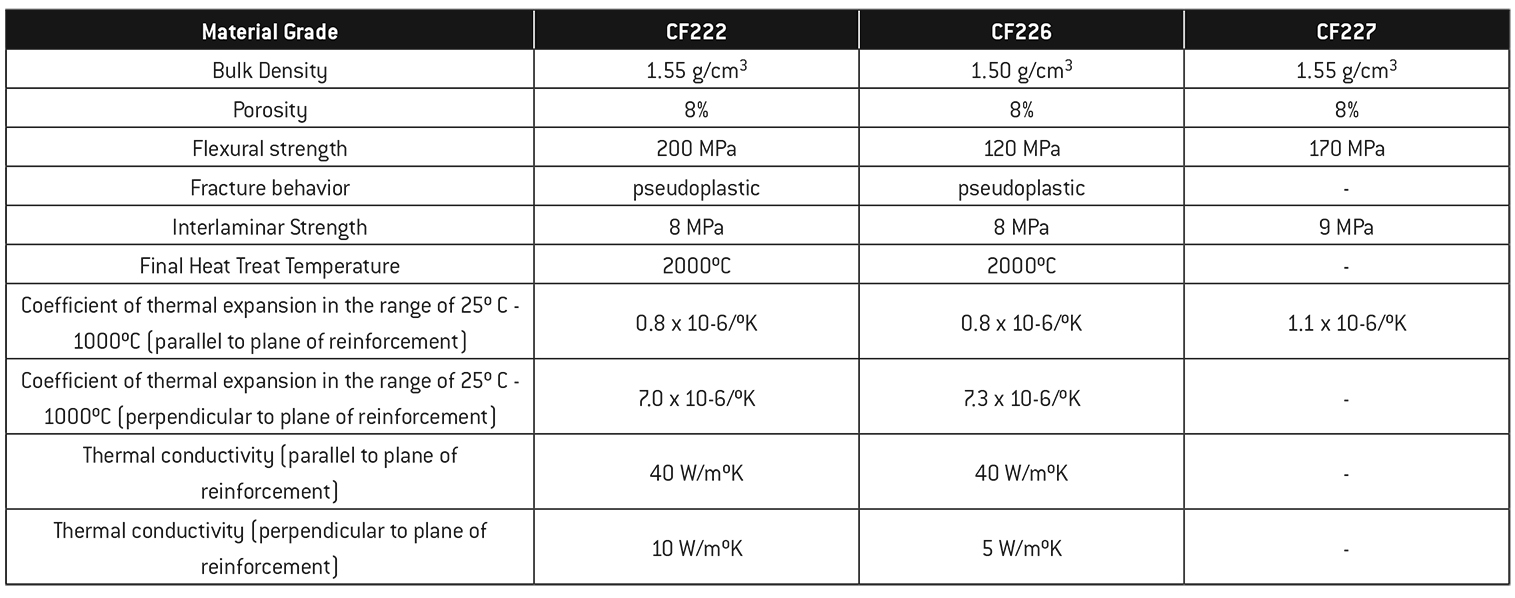
For example, Schunk Graphite often uses 3K material (Grade CF222) to manufacture nuts and bolts while 6K and 12K material (Grades CF226 and CF227 respectively) are used as furnace lining materials in a non-fully densified state or for furnace fixtures when fully densified (Table 2).
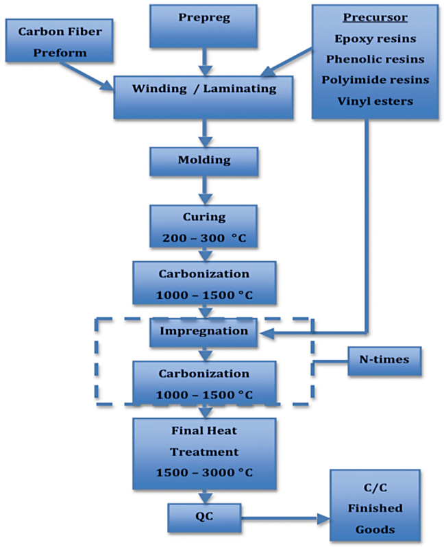
Whether to use a fully densified and non-fully densified product is a question often asked. While the process steps for carbon/carbon manufacturing (Figure 4) are different, there are reasons to use both of these materials in the high temperature furnace industry Typically, the denser the material, the stronger it will be Some applications like furnace lining material, which is not a load bearing application, can use a non-densified material.
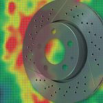
An example of densified material is the use of C/C as a TUS (temperature uniformity survey) fixture (Figure 5). Heat treaters are interested in the uniformity of their furnaces and do not want the fixture deforming over time or influencing the results. In this example a 457 mm x 610 mm x 457 mm (18” x 24” x 18”) fixture weighs 4 kg (8.8 lbs.). When performing surveys above 1050°C (1920°F), ceramic inserts must be used to avoid eutectic formation.
The process of manufacturing C/C composite material starts with a carbon fiber preform or carbon fiber cloth pre-impregnated with resin (i.e. so-called carbon fiber pre-preg material), then impregnating them with a precursor material (i.e. one of a variety of resins or esters) that will convert to carbon during the furnace cycle Depending on the process, the material is sent for winding or laminating and then off to molding The green material will then be cured and run through its initial carbonization cycle It is after this first carbonization cycle that the material is classified as non-densified and will have an open porosity of about 20%. To create a fully densified material (which is not 100% dense), the impregnation and carbonization cycles are repeated multiple times until the open porosity is about 8%.
Manufacturing time for a non-densified material is typically in the range of 4–6 weeks To manufacture fully densified material, the process time can take 4–6 months or longer The ability to use a non-densified material over a fully densified material will always be determined by the application and its end use, which is why it is important to have standard shapes/sizes readily available. The most noticeable difference to the customer will be in the lead-time and cost of material
Proper Handling and Care of C/C Composite Fixtures
Eutectic melting can occur with C/C materials at temperatures exceeding 1050°C (1922°F) but is highly dependent on the alloy(s) being run. Using ceramic barrier layers (e.g. tile, cloth), Refrasil® cloth and, in some cases, 300 series stainless steel alloy mesh screens often negates the concern over eutectic reactions. C/C fixtures can be run at or above the processing temperatures used for alloy fixtures with significantly heavier loading. If 304SS alloy screens are used as barriers, temperatures should not exceed 1120°C (2050°F).
Care must also be taken when attempting to unload these materials into open air at temperatures above 350°C (662°F) as C/C readily oxidizes over time thus destroying or severely degrading mechanical properties.
Physical damage is another concern, whether due to extremely rough handling, inadvertent dropping of the fixture or during loading/transport. Using hoist hooks, for example, is never recommended. When performing these types of operations, the breaking off of corners is one of the most commonly reported problems (Figure 6).
Finally, users should also keep records of the service history of their grids, baskets, fixtures, and internal furnace components including a history of duty cycles as a function of application, performance life and failure modes of the material. This field data helps the suppliers add to their technical expertise and improve the useful product life.
Case Study–Low Pressure Vacuum Carburizing
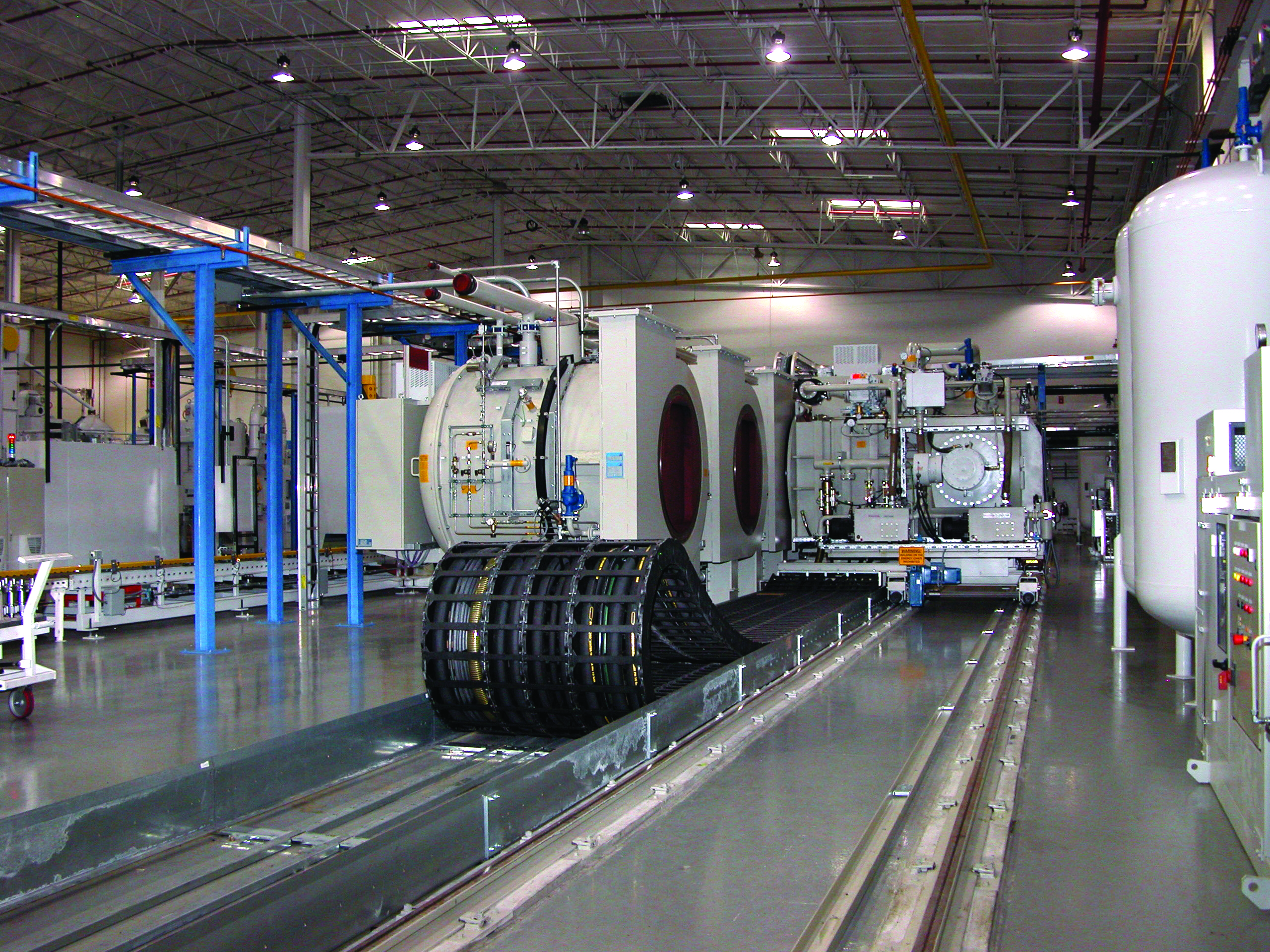
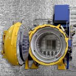
Real world experience with carbon/carbon composite fixtures is invaluable and one of the leading commercial heat treat shops, ALD Thermal Treatment in Port Huron, MI has been using carbon/carbon composite fixturing for almost 10 years in their modular low pressure vacuum carburizing furnaces (see opening spread). During this time they have learned many lessons, one of which is that not all C/C composite manufacturers produce the same product quality.
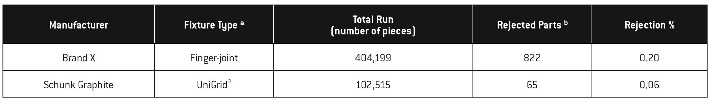
Powertrain transmission gears are one of many important products run by ALD Thermal Treatment. Given their customer’s robotic assembly operations that occur directly after heat treatment, out of roundness or any other form of dimensional change are a major concern and have the potential to damage tooling and cause unwanted downtime on the assembly line. With a rejection target of 0%, ALD Thermal Treatment has found the UniGrid® style of fixture to outperform competition (Table 3).
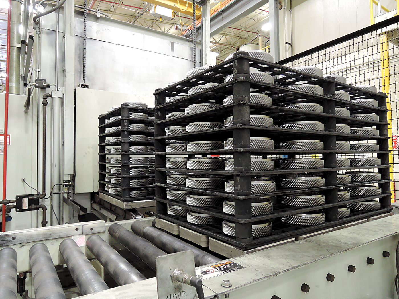
Automotive drive gears (Figure 7) of SAE 5120 are one of many examples of products that are routinely run in high volumes at ALD Thermal Treatment. Total gross load weight is 445 kg (980 lbs.). A processing temperature of 940°C (1725°F) is used to achieve the case depth requirement of 0.5 – 0.9 mm (0.020” – 0.035”) at the pitch line. Metallurgical requirements include no bainite in 70% of the case depth, less than 30% retained austenite at the tip of the gear tooth, and only finely dispersed carbides are allowed.
Fixture flatness and strength at temperature over time are major considerations. The UniGrid® design with its large openings and narrow support-ribs allow uniform heat up and improved cool down. These fixture features result in extremely repeatable part quality for all types of gears processed.
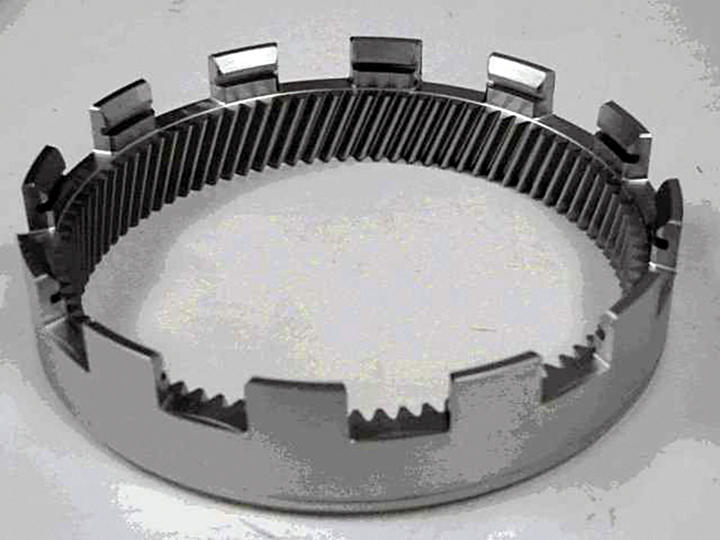
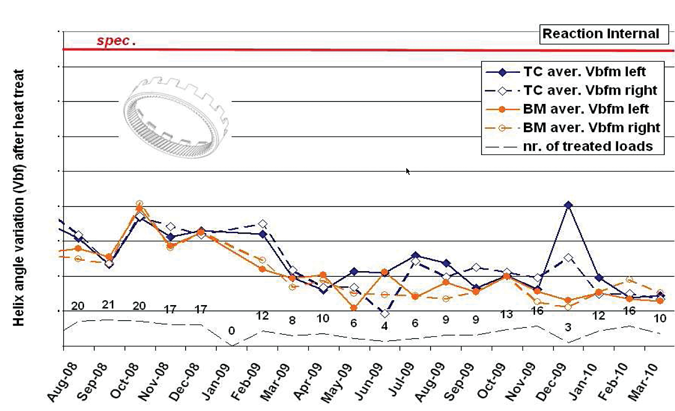
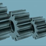
Production loads of reaction internal gears (Figure 8) are another example. In this case these parts are run on thin C/C plates. Here the material is SAE 5130 and the gears involved are 152 mm (6”) in diameter with 103 internal teeth (Figure 9). The specification requirements are for an effective case depth of 0.3 – 0.6 mm (0.012” – 0.024”) with a surface hardness of 79 – 83 HRA. The microstructure must be free of carbides and have a maximum of 30% retained austenite. The surface must be tempered martensite with no bainite present within 0.2 mm (0.008”) from the surface. The out of roundness requirement is 150 μm.
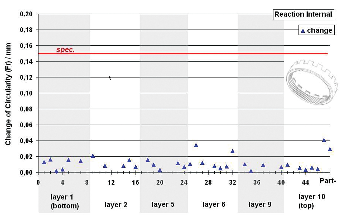
In a detailed study2, parts throughout the load were analyzed for ovality and helix angle variation before and after vacuum carburizing and high pressure dynamic gas quenching. The maximum change in ovality was 41 μm with an average change of 7 μm (Figure 10). C/C fixturing proved that, over time, not only could ovality be repeated load after load but that helix angle variation remained consistent and well below specification allowances (Figure 11). The result of this testing is that since 2006 no post heat treatment hard machining is necessary. The parts go directly to assembly after heat treatment, which is a significant cost savings to the automotive manufacturer.
Final Thoughts
The Heat Treater continues to have choices when it comes to fixtures and furnace components. With service life expectancies of 5 to 10+ years, the applications for carbon/carbon composites are virtually limitless. Not only do carbon/carbon fixtures work extremely well for all types of vacuum applications, but they can also be used for certain controlled atmosphere applications (e.g. atmosphere integral quench furnaces)
As with all other advanced technology solutions, one must match the materials capabilities with the production requirements and process application being run. In this way, maximum life and minimal problems will occur.
References
- Warwick, William and Robert Hill Jr., and Daniel H. Herring, Technical Considerations for the Use of Carbon/Carbon Composite Materials For Fixtures & Grids, Industrial Heating, December 2013.
- Heuer, Volker, High Pressure Gas Quenching (HPGQ), ALD Vacuum Carburizing Symposium, May 2012.
- Herring, Daniel H., Vacuum Heat Treatment, BNP Media Group, 2012.


 steels")


 general practice for CQI-9 and AMS2750E")
")


