


Surface hardening is an economical and technological alternative to case hardening. This is especially true for larger-sized gears. Due to the necessary high case-hardening depths required for larger case-hardened gears and due to technological boundaries (e.g., heat-treatment furnace size and heat-treatment duration) typical surface-hardening processes such as flame or induction hardening can exhibit their benefits for these parts. While flame hardening usually results in mostly through-hardened gear teeth, contour-hardened teeth can be achieved by induction hardening. As a result, the properties of surface-hardened gears significantly differ in the surface and in the core region. However, the achievable tooth root bending strength strongly depends on the gear properties, such as the surface hardening depth and the microstructure.
In the framework of this article, the influence of induction hardening on the tooth root bending strength of larger-sized gears is investigated. Therefore, different variants of larger gears that were induction hardened gap-by-gap are compared. In order to gain a deep understanding, a systematical variation of the surface hardening depth, gear size (mn = 14 mm and 20 mm), and surface condition was carried out. For example, as for the surface condition, one variant is additionally shot blasted after the hardening process. In addition, the experimental results for the induction-hardened variants are compared to a flame-hardened variant. The experimental investigations were done using a pulsator test rig and all variants are characterized by metallographic analysis and the determination of hardness depth profiles. The results are compared to the state-of-the-art for induction-hardened gears according to ISO 6336, part 5 and are additionally contrasted to experimental results for case-hardened gears with an equivalent size found in the literature.
1 Introduction
To increase the load carrying capacity of gears, they are usually heat treated. The most common process in industrial practice is case hardening. The development of wind turbines and ships shows they have become larger in recent years, and thus the gears used have also increased in size. However, case hardening may reach some limits for large gear sizes. Firstly, for case hardening, the components have to fit completely in furnaces. Secondly, the required case-hardening depth (CHD) for larger gears is in the order of several millimeters. Long process times, sometimes several days, are necessary to reach such high CHDs. Furthermore, the entire gear is heated during case hardening and has to be cooled again. The need for large furnaces and the long process times reduce the economic efficiency of the process.
Induction hardening is an alternative to case hardening with shorter process times, less energy consumption, and relatively small heat-treatment systems. With induction hardening, surface-hardening depths of several millimeters up to centimeters are feasible within short process times per tooth gap. With induction hardening, only the region of the gear hardened has to be heated. The problem is that, for induction-hardened gears, there are no recent publications available regarding the load carrying capacity of larger gears. The documented load carrying capacities (small and larger gear sizes), for example in ISO 6336-5 [1], are based on studies from the 1980s and are about 20 percent lower than for case-hardened gears. Since then, many technological advancements have been made that significantly improved the induction-hardening process. The improvements have led to a significant increase in load-carrying capacity, as shown for smaller gear sizes in [2]
2 State of the art
In designing gears, a number of gear damage types, e.g., tooth flank fracture, macropitting and tooth root breakage, must be considered. Each damage type has different damage mechanisms. What all types of damage have in common is that a shortened or prolonged overload of the gear can result in a total failure of the gearbox, either directly or through consequential damage. With ISO 6336 [3], there is a standardized procedure for calculating the load carrying capacity with regard to different types of damage. In order to calculate the load-carrying capacity of gearings, the authoritative stress number is essentially compared with an allowable stress number. The allowable stress numbers for macropitting and bending strength are given in ISO 6336-5 [1] and are based on experimental test results. If the applied stress exceeds the allowable stress, gear damage occurs. To prevent failure, there are two possibilities: Reduce the applied stress, or increase the strength of the gears. To increase the load-carrying capacity, gears are usually heat treated [4-6]. Case hardening is the de facto standard heat treatment for gears. Accordingly, numerous current studies are available on the load-carrying capacity of case-hardened gears [7-11]. Although there are some publications on induction hardened gears [12-19], there are only a few available that show experimentally secured strength numbers, especially more recent ones [20-22].
The maximum allowable stress number for surface hardened gears is about 20 percent lower than that for case-hardened gears according to ISO 6336-5 [1]. But it must be remembered that the standard regarding surface-hardened gears is based mainly on studies from the 1980s [22]. Since then, many technological advancements have been made that significantly improved the induction hardening process.
Recent experimental results with modern induction hardening processes [20, 21] show that, under appropriate conditions, induction-hardened gears can reach load carrying capacities similar to those of case-hardened gears. In FVA 660 I [2] numerous influences on the tooth root bending strength of induction-hardened gears were investigated [23] for gear sizes of mn = 2 and 4 mm. Figure 1 shows the experimental test results from FVA 660 I [2] for gears of size mn = 4 mm classified in the strength diagram according to ISO 6336-5 [1] for surface hardened and case hardened gears.
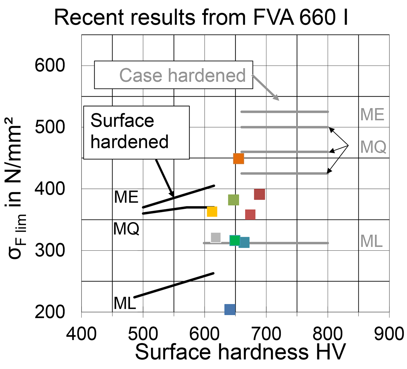
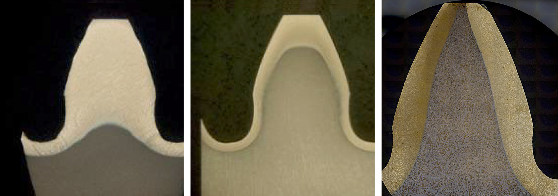
The majority of the variants show a tooth root bending strength in the range of the material quality ML and MQ for case-hardened gears. One variant of FVA 660 I [2] even has a load-carrying capacity in the range of the medium-quality MQ for case-hardened gears. Also, the surface hardness of the gears could be raised above the specifications of ISO 6336-5 [1] without the occurrence of hardening cracks. However, it can also be seen that, if the induction heat-treatment process is not adjusted properly, the resulting load carrying capacity might drop dramatically. Small induction-hardened gears are usually spin hardened, while larger sized gears are usually hardened gap-by-gap. The resulting hardening patterns and therefore the resulting microstructural properties (e.g., residual stresses) differ between spin hardened and gap-by-gap hardened gears. Figure 2 shows the achievable hardening contours. While the hardening contour can range from through hardened (left) to contour hardened (middle), gap-by-gap hardened gears are mainly near contour hardened (right). Therefore, it is not clear whether the results on small gears apply without restriction to larger gears.
3 Research objectives
The documented strength values for surface hardened gears in the standard ISO 6336-5 [1] are mainly based on research from the 1980s [22] on gears of size mn ≤ 8 mm. The surface hardened gears had load carrying capacities about 20 percent below the load-carrying capacity of case-hardened gears. Recent research on induction-hardened gears of smaller size mn = 2 and 4 mm [2, 21, 23] show that, with the latest induction-hardening processes, load carrying capacities similar to case-hardened gears can be achieved. In contrast, no comprehensively documented strength numbers are yet available for induction-hardened gears of larger sizes (module mn > 8 mm). Thus, in the research project AiF Nr. 19630 N/1 / FVA 660 II [24], the tooth root load carrying capacity for gears of larger size (mn ≥ 8 mm) was investigated. Various influences on the tooth root load capacity such as the surface hardening depth (SHD), the gear size, and blasting treatment — among others — were investigated. In a previous article [20], it was shown induction-hardened gears of a larger gear size can also reach load-carrying capacities similar to case-hardened gears.
The main objective of the investigations within the scope of this publication is to examine the influence of the hardening depth, the gear size, and blasting treatment on the load carrying capacity of induction-hardened gears of larger size. In addition, the experimental results of the induction-hardened variants are compared to a flame-hardened variant. For this purpose, seven selected variants from the research project are presented and analyzed. Lastly, the experimentally determined load carrying capacities of the surface-hardened variants are compared to a case-hardened reference. This is done on the basis of the following points:
- Characterization of base material.
- Characterization of gears after heat treatment.
- Comparison of the achieved load carrying capacities in pulsator tests.
- Classification of the results in the strength field according to ISO 6336-5 [1].
4 Test program and methods
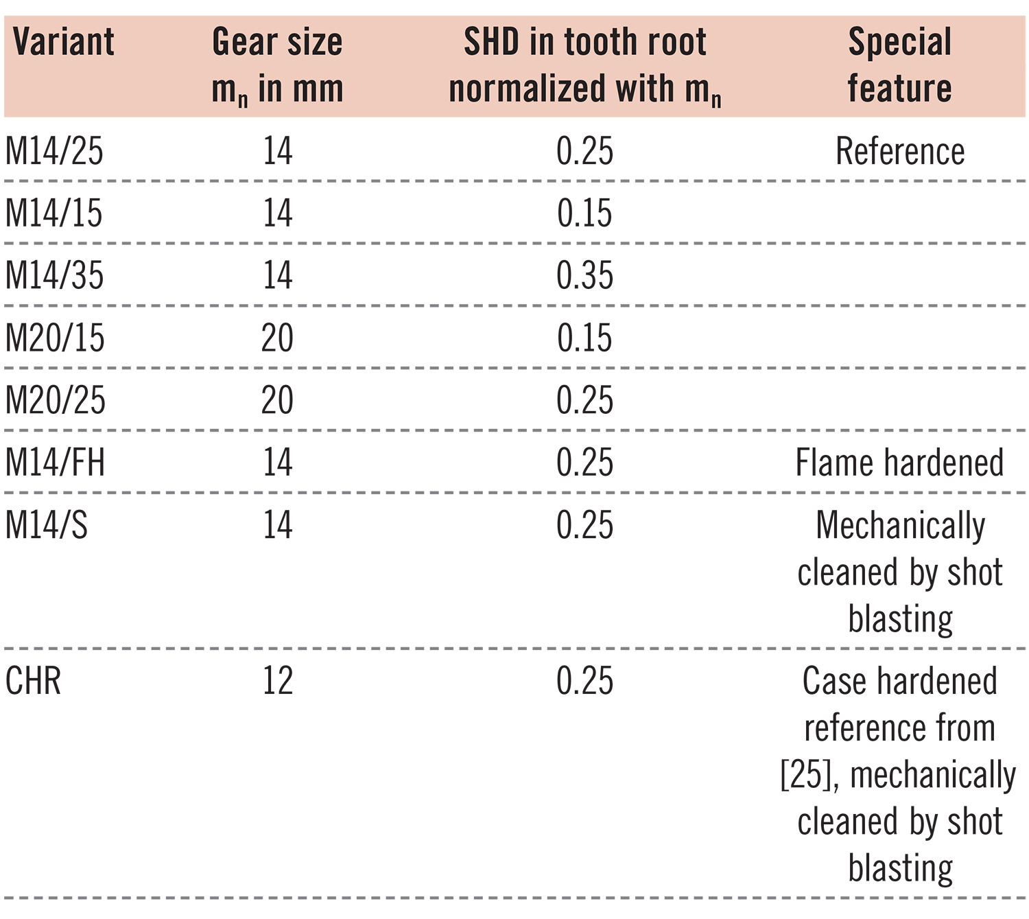
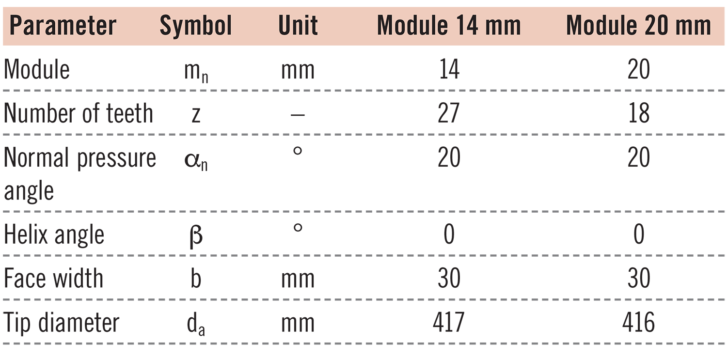
The test program includes a selection of different induction hardened variants from the research project FVA 660 II [24], as well as one flame-hardened variant. The variants are listed in Table 1. The variants differ in gear size and surface hardening depth (SHD). The variant M14/S is mechanically cleaned (by shot blasting); apart from that, it is identical to the reference variant M14/25. The main gear dimensions are in Table 2.
The induction hardened gears were gap-by-gap hardened on a single tooth hardening system of the company EFD Induction. In the hardening process, the inductor was moved through the tooth gap along the tooth width. No pre-heating took place. For optimal hardening results, the inductor was fitted with ferrotron concentrators. During the entire hardening process, the mating flank was cooled with a quenchant to prevent unwanted tempering. After heating, the just-hardened gap was instantly quenched as well. The quenchant was a polymer-water solution. After hardening, the induction-hardened gear was tempered for 2 hours at 150°C. The tooth root is in milled condition. After the hardening process, variant 7 was mechanically cleaned by shot blasting.
The flame-hardened variant M14/FH was flame-spin hardened with a hardening temperature of 900°C. After hardening, the flame-hardened gears were tempered for 5 hours at 150°C.
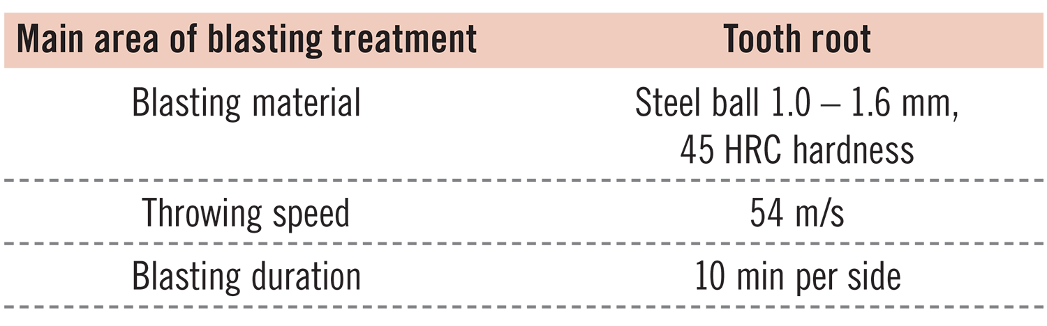
The variant M14/S was mechanically cleaned by shot blasting. The parameters used are in Table 3.
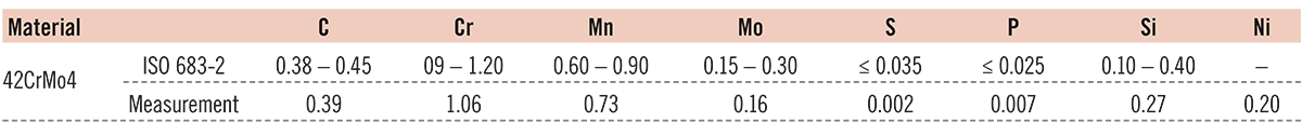
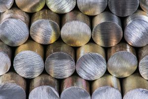
All variants are from one batch of the material 42CrMo4, which is typical for surface hardening. The diameter of the raw material was 430 mm with a reduction ratio of 4:1. The following description is taken from [20]: The material 42CrMo4 was quenched and tempered before heat treatment. For the pre-hardening process, the disk blanks (thickness of the disks: 40 mm) were kept in the furnace for 6 hours at 870°C and then quenched in an oil bath. Subsequently, the disc blanks were tempered at 560°C. For this purpose, the disk blanks were heated to the target temperature for 2.5 hours, kept at the desired temperature for 7 hours and then cooled to 300°C in a controlled manner within 5 hours. The tensile strength of the individual disks after pre-tempering was between approximately 890 and 950 N/mm2. The material composition was determined by optical emission spectroscopy (S-OES). Table 4 shows the material composition of the material used. All values lie within the target range defined in [26].
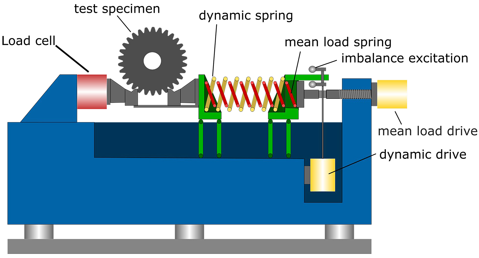
The tests to determine the tooth root load carrying capacity of the investigated variants were carried out on a mechanically excited resonance pulsator. The schematic setup is shown in Figure 3.
The test methods are described in [20, 24]. The following paragraphs are based on the descriptions given there:
The resulting tooth root stress depends on the pulsator force, gear geometry, and clamping points.
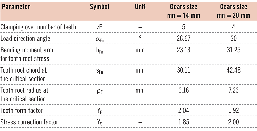
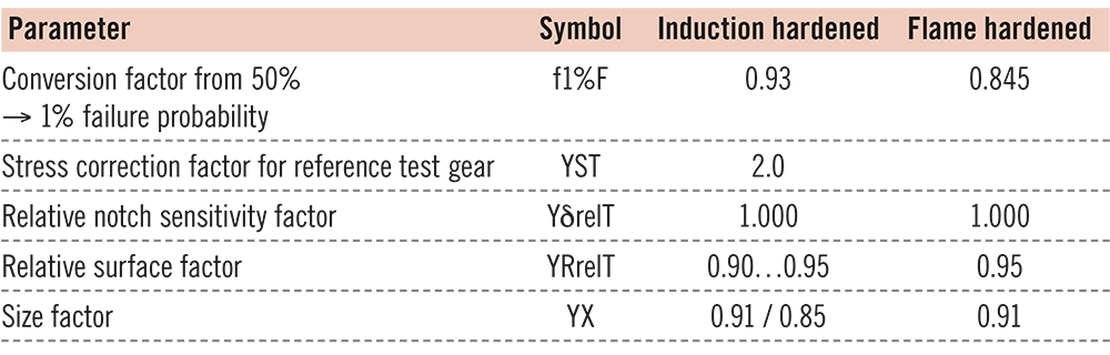
ISO 6336-3 [27] describes how to convert the pulsator force into the resulting tooth root stress using geometrical values. The geometrical values for the calculation of the tooth root stress of the investigated gears are in Table 5. According to ISO 6336-5 [1], the fatigue strength parameters given in the same standard for the tooth root bending strength σF lim and σFE apply to standard reference test gears under standard test conditions in the running test and 1 percent failure probability. With the aid of the influencing factors defined in ISO 6336-3 [27], strength values can be determined for different gears for the conditions at hand. It is also possible to classify experimental test results in the strength field of the standard. As σF lim and σFE are given for running gears, the test results from the pulsator tests need to be converted to the conditions in gear-running tests. This is done using the established conversion factor of 0.9 [28]. The other required factors for the calculation according to ISO 6336-3 [27] were determined following the standard. The factors influencing the tooth root fatigue strength for the investigated variants are in Table 6. The conversion factor f1%F, for converting 50 percent to 1 percent failure probability depends on the material, the heat treatment, and the blasting treatment. The conversion factor can be determined in two ways [20, 24]: In the first method, the conversion factor is determined based on the standard deviation of the tests performed for finding the fatigue strength. The second, more-common approach uses a conversion factor based on literature sources and an underlying statistical analysis of a larger test database. For the induction hardened variants, the conversion factor was determined in the FVA 660 II project [24] according to Method 1. The FH variant showed significantly larger scatter compared to the induction-hardened test series investigated in FVA 660 II [24], therefore the conversion factor from FVA 660 I [2] was applied for induction-spin-hardened gears. The applicability was checked on the basis of the test scatter. In comparison with literature for the conversion factor of case-hardened gears [28], it can be stated that the test scatter of the induction-hardened variants is comparable to the empirical values of case-hardened and mechanically-cleaned gears.
5 Material and gear characterization
Figure 4 shows the microstructure of the core area of a representative gear. As all variants are from the same batch of gear material with the same pre-hardening treatment, the core microstructure of all variants is the same. The microsection shows a hardened and tempered microstructure with clear segregations.

The segregations are within the expected range for 42CrMo4 and the used diameter of raw material.
Figure 5a shows a metallographic cross section of a whole tooth of variant M14/25. The microsection shows the hardening contour along the tooth surface. The hardening contour is typical for gap-by-gap induction-hardened gears. The brightly colored martensitic surface layer is in contrast to the dark-core microstructure. The surface layer shows the same segregations as the core microstructure. Because of the short heating times and fast quenching, the transition layer between the martensitic surface and the quenched and tempered core microstructure is very small. The hardening contour is similar for all investigated induction-hardened variants and only differs in the hardening depth and/or the gear size. For all induction-hardened gears, the hardening contour is thickest at the tooth flanks and lowest in the area of the 30° tangent to the tooth root fillet. The tooth rounding is in between. Figure 5b shows the cross section of the flame hardened variant M14/FH in contrast to the induction hardened variants. The whole tooth is hardened, and the transition from martensitic to the core microstructure is below the 30° tangent to the tooth root fillet. The transition layer is much larger than that of the induction-hardened variants and shows a smooth transition from the hardened tooth to the core microstructure.
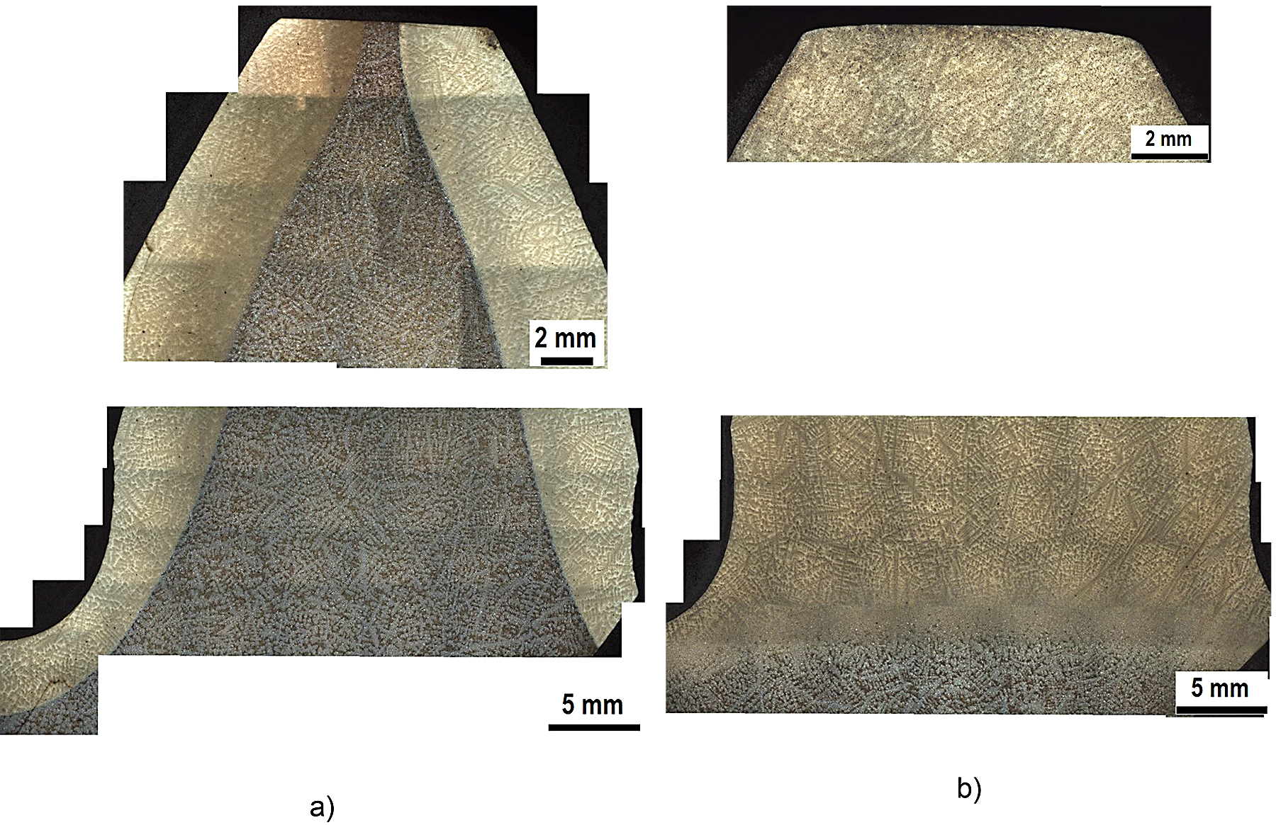
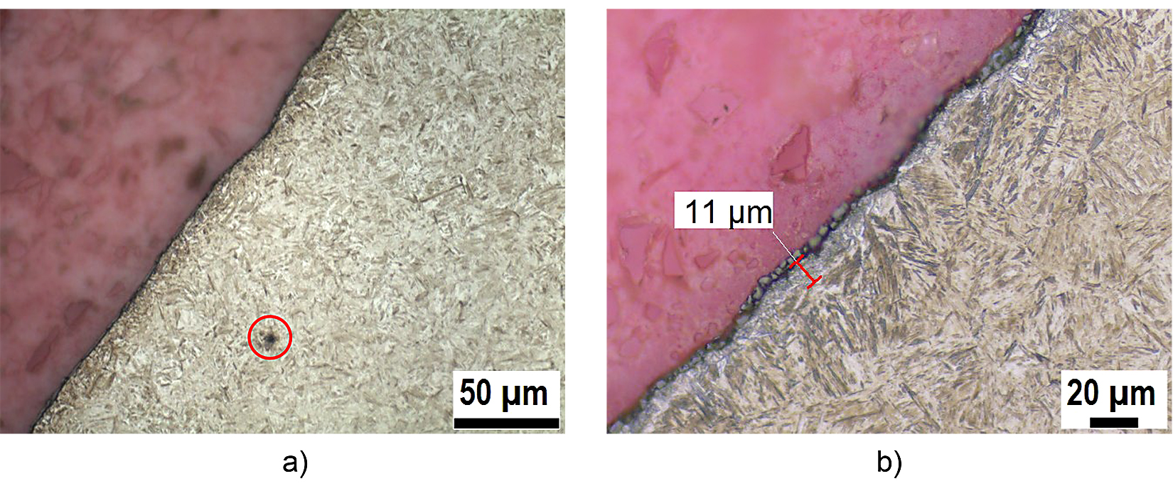
Figure 6 shows the hardened surface layer in detail. All variants show a similar microstructure in the surface layer. The surface layer is almost completely martensitic with only little retained austenite.
Variant M14/35 shows a certain decarburization at the surface over the first few micrometers (Figure 6b) and therefore proeutectoid ferrite. The detailed metallographic microsections of the surface layer show a few non-metallic inclusions as highlighted in Figure 6a.
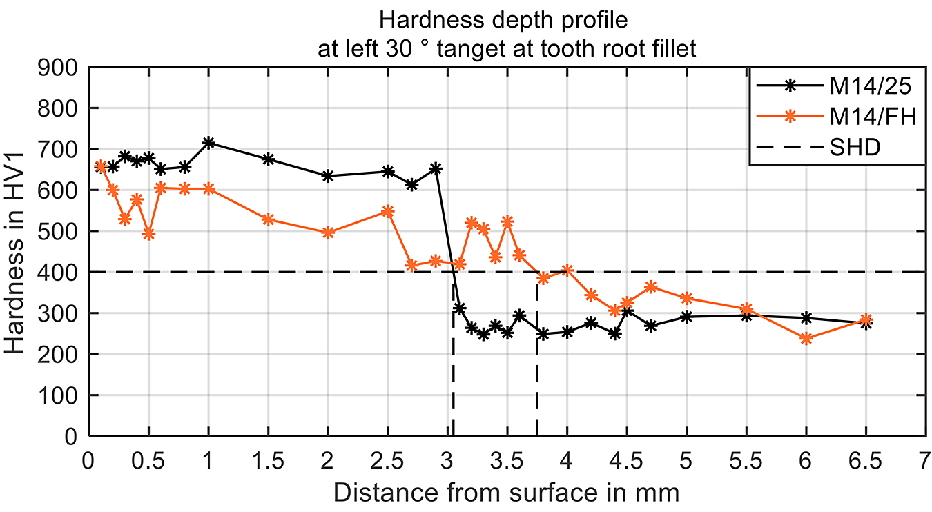
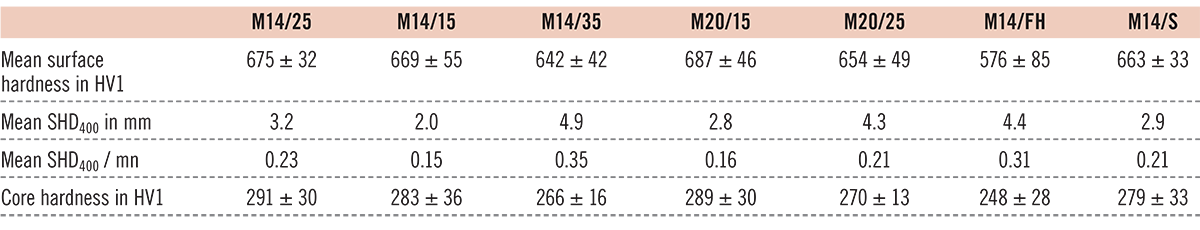
For all variants, the hardness-depth profiles were measured in the left and right tooth root at 30° tangents to the tooth root fillet. Figure 7 shows the hardness depth profiles of the representative induction-hardened variant (M14/25) and of the flame-hardened variant (M14/FH) for the left 30° tangent. The hardness-depth profile of the induction-hardened variant M14/25 is typical for gap-by-gap hardened gears. The surface hardness is about 675 HV1. The hardness stays more or less the same up to the depth where the SHD is reached. For this investigation, the hardness limit to determine the SHD was chosen to be 400 HV1 to have a better comparability within the variants and with earlier research. Close to the SHD, a steep transition of the hardness from about 650 HV1 to the core hardness of about 300 HV1 occurs. The SHD differs from the left to the right sides. The hardness-depth profile of the flame-hardened variant (M14/FH) shows a surface hardness similar to that of the induction-hardened variant but has some fluctuations. The transition from surface-to-core hardness is gradual. In the area of the SHD, the hardness fluctuates again until it drops to the core hardness. The core hardness for the induction and flame-hardened variants is more or less the same, as they are from the same batch of base material with the same preheat treatment. The main parameters that describe the hardness depth profiles of all variants are in Table 7. The SHD in Table 7 is the mean value for the left and right sides. The surface hardness is the mean value of the first three measurements (0.1, 0.2, and 0.3 mm below the surface) of the left and right sides.
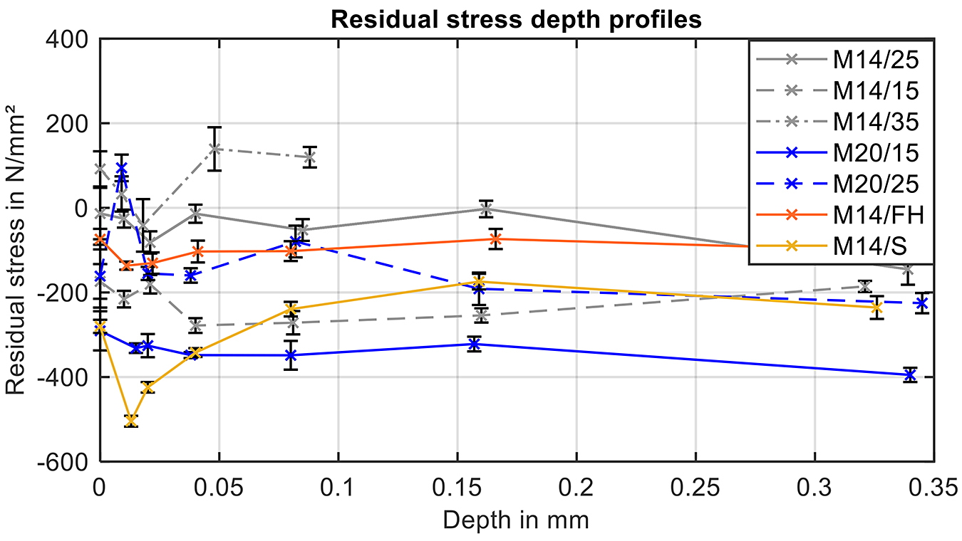
For the investigated variants, the residual stress-depth profiles were determined by X-ray measurements in the relevant tooth root area. The residual stresses were measured with an X-ray diffractometer, type Seifert (XRD 3003 PTS). Figure 8 shows the resulting residual stress-depth profiles. Overall, the residual stresses are relatively low below the surface. Some variants have practically no residual stresses at the measured depth. Case-hardened gears usually have higher compressive residual stresses in the hardened-surface layer. However, one must bear in mind that case-hardened gears are usually mechanically cleaned by shot blasting. The variant M14/S has the highest compressive residual stress of all variants close to the surface due to the blasting treatment.
In summary: The microstructure and hardness depth profile of the investigated variants are typical for an induction respectively flame hardened specimen. The microstructure and the hardness depth profile show no anomalies. Further information regarding the detailed microstructure, hardness depth profiles, and residual stress profiles of the other variants can be seen in the final report of FVA 660 II [24]
6 Experimental results
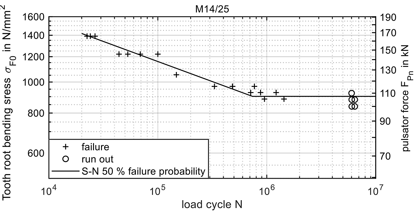
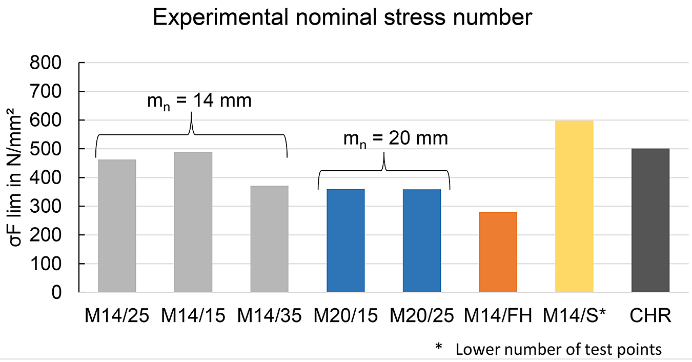
To obtain the S-N curves for tooth root bending strength, experimental tests were carried out at different load levels. The endurance limit was determined with the staircase method according to [29]. To determine the high-cycle fatigue strength, tests at two load levels with 3-5 test points each were performed, if possible (load limit of pulsator test rig). Figure 9 shows by way of example the test results and the resulting S-N curve of the variant M14/25. Similar S-N curves for the other variants were determined and are in the final report of FVA 660 II [24]. The resulting endurable nominal tooth root bending strength for 50 percent failure probability was then converted to the experimental nominal stress number for bending σF lim, as described in Section 4. The resulting stress numbers for the variants at hand are shown in Figure 10 and compared to the experimental stress number of the case-hardened variant. The variants of gear size mn = 14 mm have an experimental stress number for bending about 370 to 490 N/mm2. The gears of size mn = 20 mm are overall a little bit lower, with stress numbers about 360 N/mm2. The flame-hardened variant M14/FH has the lowest stress number with 280 N/mm2. The mechanically-cleaned (by shot blasting) variant has the highest tooth root bending strength with nearly 600 N/mm2, which is about 30 percent higher than the reference variant M14/25. The tooth root bending strength of the induction-hardened “standard” variants is only a little below the case-hardened and mechanically-cleaned (by shot blasting) reference CHR. The mechanically-cleaned, induction-hardened variant M14/S has a higher tooth root bending strength than the case-hardened reference. This shows induction-hardened, larger-sized gears can reach similar tooth root bending strength numbers as case-hardened gears of similar size.
7 Discussion
The experimental test results show a clear influence of different parameters. The first parameter to be discussed is the surface-hardening depth. As shown earlier in this article, some variants of gear size mn = 14 and 20 mm have different SHDs by intention. Figure 11 shows the relative tooth root bending strength of the gears taken from Figure 10 normalized with the tooth root bending strength of the variant M14/25 for the variants of gears size mn = 14 mm and M20/25 for the variants of gear size mn = 20 mm. The resulting diagram shows a clear influence of the SHD on the tooth root bending strength: With decreasing SHD, the tooth root bending strength rises. The tooth root bending strength of the variant with an SHD of
0.35 〈 mn reaches only 80 percent of the tooth root bending strength of the variants with lower SHD.
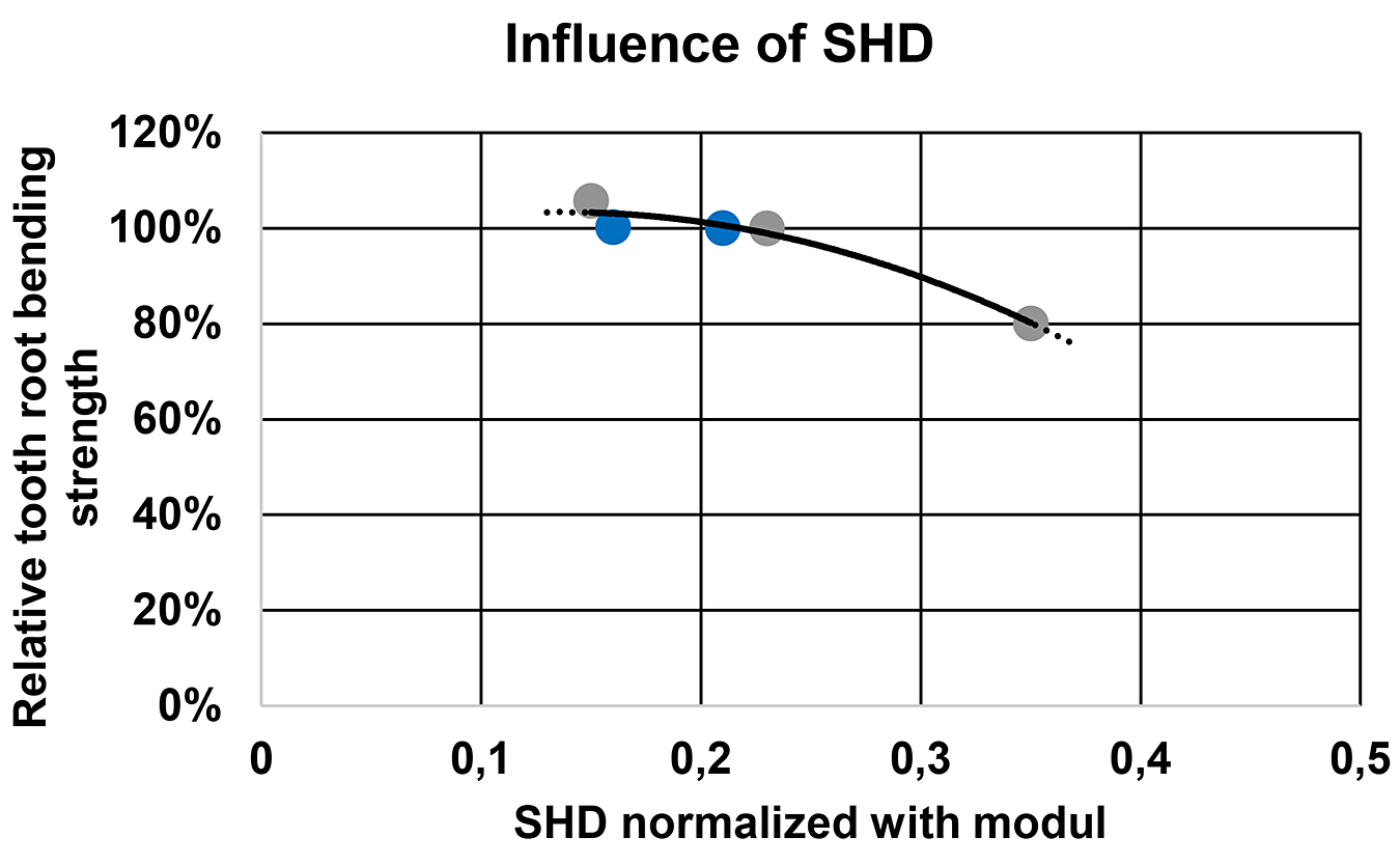
The variant with an SHD of 0.15 〈 mn has a slightly higher tooth root bending strength than the variants with 0.25 〈 mn, These results are in correlation with the measured residual stresses, which show higher compressive residual stresses in the hardened layer with smaller SHD respectively, even tensile residual stresses for variant M14/35 with the largest SHD. Presumably, there is a limit for the minimum SHD where the tooth root bending strength will drop significantly. In conclusion and based on the herein determined results for induction hardened gears from gear size mn = 14 to 20 mm, there seems to be an optimal SHD400 in the range of 0.15 to 0.25 〈 mn. This is in accordance with earlier research on induction-hardened gears in [22], whereas in [22], a SHD of about 0.15 〈 mn was not investigated.
The drop in the tooth root bending strength of variant M14/35 might be due to the decarburization of the surface layer and the resulting proeutectoid ferrite on the one hand and tensile residual stresses in the surface area on the other. This suggests there is a maximum (absolute) SHD that should not be exceeded for induction-hardened gears of larger size. Further research is needed to prove this hypothesis.
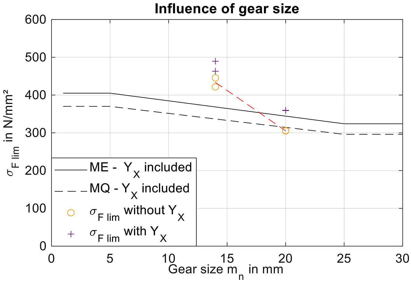
The gear size has another influence on the load carrying capacity of induction-hardened gears of larger size. Figure 12 shows the maximum tooth root bending strength for induction hardened gears according to ISO 6336-5 [1] for the material quality grades ME and MQ multiplied by the size factor YX over the gear size in comparison to the experimental test results of variants M14/25, M14/15, M20/15 and M20/25. The experimental tooth root bending strength numbers of the gears of size mn = 14 mm are higher than the standard specification for that gear size and material quality, while the gears of size mn = 20 mm align with the standard specification. To evaluate the influence of the gear size, the experimental test results are shown once with size factor YX taken into account and once without. The experimental test results without size factor YX suggest the influence of the gear size is underestimated in ISO 6336-3 [27] for induction-hardened gears. The red dotted line shows the influence factor according to the experimental test results for the investigated variants. It must be remembered that the standard is mainly based on case-hardened gears. In order to reliably determine the influence of the gear size, further investigations should be considered.
8 Classification of the test results
The test results are classified according to the standard ISO 6336-5 [1]. Figure 13 shows the experimental nominal stress number of the surface hardened variants and the case-hardened reference within the allowable stress numbers diagram for bending from ISO 6336-5. The induction-hardened variants exceed the hardness specifications for induction-hardened gears. The surface hardness of the induction-hardened variants is about 650 to 700 HV, while the maximum surface hardness for surface-hardened gears according to the standard is 615 HV. The induction-hardened variants with gear size mn = 20 mm and variant M14/35 have a tooth root bending strength in the range of the extrapolated line for the material quality MQ. Variants M14/25 and M14/15 are significantly above the extrapolated line for material quality ME and reach a tooth root bending strength similar to that of the case-hardened reference. This is the case despite the fact that the case-hardened reference is mechanically cleaned by shot blasting while the induction-hardened variants are not. The characteristic numbers of these variants are in the region for the material quality MQ of case-hardened gears with respect to both the surface hardness and the bending strength. The mechanically cleaned (by shot blasting) variant M14/S reaches the highest tooth root bending strength of all variants and lies well above the material quality ME for case-hardened gears with a tooth root bending strength of nearly 600 N/mm2. The flame-hardened variant M14/FH lies just above the line for the material quality ML for surface hardened gears.
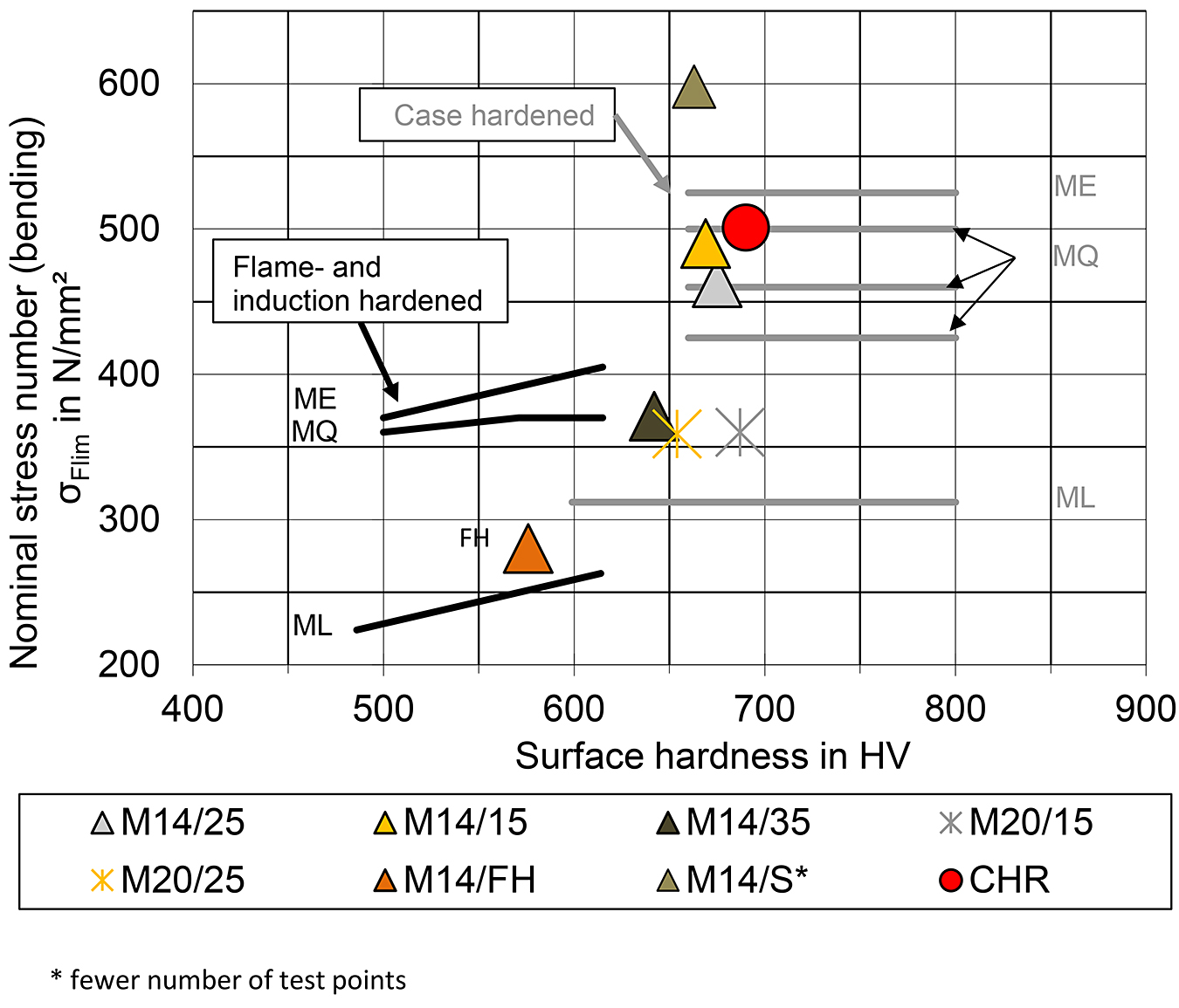
* fewer number of test points
The classification shows that induction-hardened, larger-sized gears can endure much higher bending stresses than indicated in ISO 6336-5 [1]. It must be remembered that the standard regarding induction-hardened gears is based mainly on studies from the 1980s. This study shows that, with the technological progress in the induction-hardening process, higher tooth root bending strength numbers similar to case-hardened gears can be achieved. Therefore, induction hardening can be an alternative to case hardening for larger gears. As mentioned before, induction hardening has shorter heat-treatment times and lower energy consumption than does case hardening. To reach such high load carrying capacities, some preconditions must be fulfilled:
For gear sizes from mn = 14 to 20 mm, the SHD400 should be in the range of 0.15 to 0.25 〈 mn.
The SHD on the left and right sides of the tooth should be more or less equal.
The surface hardness should be in the range of 650 to 750 HV, but hardening cracks must be avoided.
9 Summary
Surface hardening has certain advantages over case hardening in terms of process economy, but older research and the standard suggest that the load carrying capacity is about 20 percent lower than that of case-hardened gears. Recent studies show, for smaller gear sizes, that is no longer the case. To apply these findings to larger gears, the load-carrying capacity of induction-hardened gears of larger size was studied.
The aim of the investigations in this article was to show some crucial parameters influencing the load carrying capacity of induction-hardened gears of larger size. To achieve that, seven selected variants from the research project AiF Nr. 19630 N/1 / FVA 660 II [24] were presented. As a basis for further discussion, the base material and the gear properties of the selected variants were analyzed in detail. For this characterization, the microstructural condition, the hardness depth curves, and residual stress depth profiles were considered. The experimental results of the pulsator tests were then presented. The experimental test results show a clear influence of the SHD, gear size, and optional blasting treatment.
Furthermore, the experimental load carrying capacity for induction-hardened gears of larger size was compared to that of case-hardened gears and proves the beneficial applicability for an appropriate induction-hardening process.
In conclusion, the research shows some crucial parameters to achieve high bending-strength numbers for induction-hardened gears. In order to achieve a high tooth root load-carrying capacity, a surface hardness exceeding the standard specifications for induction-hardened gears as well as a hardness pattern close to the contour and as uniform as possible over the gear circumference must be reliably set. The occurrence of hardening cracks must be reliably avoided. Furthermore, care must be taken to ensure sufficient hardening depth in the area of the 30° tangent, which is important for tooth root load carrying capacity.
If these requirements are met, induction hardening can be a time-saving and cost-effective alternative to case-hardened gears for certain applications.
Acknowledgements
The findings presented here are based on research project IGF No. 19630 N/1 of the German Research Association for Power Transmission Technology e.V. (FVA); funded in part by the FVA and through the German Arbeitsgemeinschaft industrieller Forschungsvereinigungen e.V. (AiF) (German Consortium of Industrial Research Associations) within the framework of the program for the promotion of joint industrial research (IGF) by Bundesministerium für Wirtschaft und Energie (BMWi) (Federal Ministry for Economic Affairs and Energy) on the basis of a resolution of the German Bundestag. The authors would like to thank the FVA / AiF and the members of the project-accompanying committee for their funding and support. The results shown were taken from the corresponding final report of the research project FVA 660 II [24]. Further information on the influence of different materials and hardening depths as well as other influences on the tooth root load carrying capacity of induction-hardened gears are in the final report.
References
- Calculation of load capacity of spur and helical gears – Part 5: Strength and quality of materials, ISO 6336-5, ISO, Aug. 2016.
- D. Nadolski, F. Dobler, M. Steinbacher, T. Tobie, Zoch H.-W., and K. Stahl, “FVA-Nr. 660/I – Heft 1186 – Induktionshärtung: Tragfähigkeit und Festigkeitseigenschaften induktionsgehärteter Zahnräder,” (Load capacity and strength properties of induction hardened gears), Frankfurt am Main, 2016.
- Calculation of load capacity of spur and helical gears – Part 1: Basic principles, introduction and general influence factors., 6336-1, ISO, Nov. 2019.
- G. Niemann and H. Winter, Maschinenelemente Band 2: Getriebe allgemein, Zahnradgetriebe – Grundlagen, Stirnradgetriebe (Machine Elements Volume 2: Gears in General, Gearboxes – Basics, Spur Gears): Springer Verlag, 2002.
- H. Gießmann, Wärmebehandlung von Verzahnungsteilen: Effektive Technologien und geeignete Werkstoffe (Heat treatment of gearing parts: Effective technologies and suitable materials), 3rd ed. Renningen: expert verlag, 2017.
- J. Ruge and H. Wohlfahrt, Technologie der Werkstoffe: Herstellung, Verarbeitung, Einsatz (Materials technology: Production, processing, use), 9th ed. Dordrecht: Springer, 2013. [Online]. Available: http://gbv.eblib.com/patron/FullRecord.aspx?p=1317744
- D. Kratzer, F. Dobler, T. Tobie, T. Hoja, M. Steinbacher, and K. Stahl, “Effects of low-temperature treatments on surface hardness, retained austenite content, residual stress condition and the resulting tooth root bending strength of case-hardened 18CrNiMo7-6 gears,” Proceedings of the Institution of Mechanical Engineers, Part C: Journal of Mechanical Engineering Science, vol. 64, 2019, doi: 10.1177/0954406219846160.
- D. Kratzer, J. König, T. Tobie, and K. Stahl, “Effects of different shot peening treatments in combination with a superfinishing process on the surface durability of case-hardened gears,” in Fall Technical Meeting 2020, 2020.
- D. Fuchs, C. Güntner, T. Tobie, and K. Stahl, “Geeignete Werkstoffwahl für Stirnräder großer Baugröße/Suitable Material Selection for Large Size Cylindrical Gears,” HTM Journal of Heat Treatment and Materials, vol. 76, no. 1, pp. 19–35, 2021, doi: 10.1515/htm-2020-0002.
- D. Fuchs, S. Schurer, T. Tobie, and K. Stahl, “On the determination of the bending fatigue strength in and above the very high cycle fatigue regime of shot-peened gears,” Forsch Ingenieurwes, vol. 20, p. 229, 2021, doi: 10.1007/s10010-021-00499-2.
- J. König, “Einflüsse der Oberflächenbeschaffenheit und Schmierungszustand auf die Flankentragfähigkeit einsatzgehärteter Verzahnungen,” (Influences of surface finish and lubrication condition on the flank load capacity of case-hardened gears), 2016.
- V. Savaria, F. Bridier, and P. Bocher, “Predicting the effects of material properties gradient and residual stresses on the bending fatigue strength of induction hardened aeronautical gears,” International Journal of Fatigue, vol. 85, pp. 70–84, 2016, doi: 10.1016/j.ijfatigue.2015.12.004.
- D. Rodman et al., “Induction Hardening of Spur Gearwheels Made from 42CrMo4 Hardening and Tempering Steel by Employing Spray Cooling,” steel research int., vol. 82, no. 4, pp. 329–336, 2011, doi: 10.1002/srin.201000218.
- D. Schlesselmann, C. Krause, and M. Schaudig, “Effect of Inductor Design on the Hardness after Induction Hardening using Line Inductors,” HTM, vol. 73, no. 4, pp. 202–210, 2018, doi: 10.3139/105.110354.
- V. Rudnev, D. Loveless, R. Cook, and M. Black, “Induction Hardening of Gears: a Review, Part 1,” Heat treatment of Metals, no. 4, pp. 97–103, 2003.
- V. Rudnev, D. Loveless, R. Cook, and M. Black, “Induction Hardening of Gears: a Review, Part 2,” Heat treatment of Metals, no. 1, pp. 11–15, 2004.
- R. I. Navin, P. D. Babu, P. Marimuthu, and S. S. Phalke, “Distribution of Residual Compressive Stresses in Induction Hardened Steel Gears: Effect of Parameters on Distortion, Hardness and Phase Composition,” Met Sci Heat Treat, vol. 63, 7-8, pp. 449–455, 2021, doi: 10.1007/s11041-021- 00710-9.
- M. Parvinzadeh, S. Sattarpanah Karganroudi, N. Omidi, N. Barka, and M. Khalifa, “A novel investigation into edge effect reduction of 4340 steel spur gear during induction hardening process,” Int J Adv Manuf Technol, vol. 113, 1-2, pp. 605–619, 2021, doi: 10.1007/s00170-021-06639-w.
- H. Cermak et al., “Influence of base material, tempered condition and hardening pattern on the residual stress profile of induction hardened gears,” Forsch Ingenieurwes, vol. 83, no. 3, pp. 571– 577, 2019, doi: 10.1007/s10010-019-00341-w.
- H. Cermak, T. Tobie, and K. Stahl, “Flame and Induction Hardening – An Advantageous Alternative to Case Hardening for Large Size Gears?” HTM, Band 77, Heft 2, 2022, doi: 10.1515/htm-2021- 2001.
- C. Güntner et al., “Load Carrying Capacity of Induction “Contour“ Hardened Gears,” in Proceedings of the 5th International Conference on Steels in Cars and Trucks (SCT), 2017.
- T. Weiß, H. Rettig, and H. Winter, FVA-Nr. 29 – Heft 127 – Abschlussbericht: Induktions- und Flammhärtung: Belastbarkeit von induktiv- bzw. flammgehärteter Zahnräder (Induction and flame hardening: load capacity of induction- and flame-hardened gears), 1983.
- F. Dobler, T. Tobie, K. Stahl, D. Nadolski, M. Steinbacher, and F. Hoffmann, “Influence of hardening pattern, base material and residual stress condition on the tooth root bending strength of induction hardened gears,” in Proceedings of the International Conference on Power Transmissions, 2016, pp. 287–294.
- H. Cermak, T. Tobie, and K. Stahl, “FVA-Nr. 660/II – Induktivhärten großer Zahnräder – Abschlussbericht – Einfluss aus Baugröße, Werkstoff und Randhärtetiefe auf die Zahnfußtragfähigkeit induktivgehärteter Stirnräder größerer Baugröße: Noch nicht veröffentlicht,” (Induction Hardening of Larger Gear: Influence of Gear Size, Gear Material and Surface Hardening Depth on the Tooth Root Bending Strength of Induction Hardened Gears of larger Size), Forschungsvereinigung Antriebstechnik e.V., Frankfurt am Main, 2022.
- C. Güntner, T. Tobie, and K. Stahl, “FVA-Nr. 740/I – Heft 1303 – Härtbarkeit Großzahnräder – Abschlussbericht: Einflüsse aus Baugröße, Härtbarkeit und Einsatzhärtungstiefe und deren Gesamtwirkung auf die Zahnfußtragfähigkeit einsatzgehärteter Stirnräder größerer Baugröße,” (Hardenability of large gears: Influences of size, hardenability and case hardening depth and their overall effect on the tooth root load carrying capacity of case hardened cylindrical gears of larger size), Forschungsvereinigung Antriebstechnik e.V., Frankfurt am Main, 2018.
- Heat-treatable steels, alloy steels and free-cutting steels – Part 2: Alloy steels for quenching and tempering, 683-2, ISO, Sep. 2018.
- Calculation of load capacity of spur and helical gears – Part 3: Calculation of tooth bending strength, 6336-3, ISO, Nov. 2019.
- K. Stahl, K. Michaelis, B.-R. Höhn, and H. Winter, “FVA 304 – Lebensdauerstatistik – Abschlussbericht,” (Durability statitistics). Forschungsvorhaben Nr. 304, Abschlussbericht, Frankfurt am Main, 1999.
- M. Hück, “Ein verbessertes Verfahren für die Auswertung von Treppenstufenversuchen,” (An improved method for the evaluation of stair case tests), DVM Deutscher Verband für Materialprüfen, pp. 147–167, 1983.
- About the authors
- Holger Cermak, Dr. Thomas Tobie, and Prof. Karsten Stahl are with the Gear Research Center (FZG) – Technical University of Munich (TUM).
Printed with permission of the copyright holder, the American Gear Manufacturers Association, 1001 N. Fairfax Street, Suite 500, Alexandria, Virginia 22314. Statements presented in this paper are those of the authors and may not represent the position or opinion of the American Gear Manufacturers Association. (AGMA) This paper was presented October 2022 at the AGMA Fall Technical Meeting. 22FTM14


 general practice for CQI-9 and AMS2750E")


