


Straight-tooth bevel gears are the simplest type of bevel gears that can be used for power transmission between intersecting shafts. They are commonly referred to as straight bevel gears, for brevity. Shafts for power transmission with straight bevel gears are usually mounted at a shaft angle of 90 degrees but can be designed to work at a wide range of shaft angles. They operate with efficiency around 98 percent or even better. They are widely applied in low-speed applications or static loading conditions [1]. The most traditional application of straight bevel gears is in differential drives in which the speed is low and the load type is mainly static.
Straight bevel gears are conical. Their teeth are tapered in both tooth thickness and tooth height [2]. In one end, the tooth height is large, while in the other end, it is small. These gears impose both radial and thrust loads on their bearings.
The great pioneer in the bevel gear field was William Gleason, founder of The Gleason Works in 1865. In 1874, William Gleason invented the first bevel gear planer. That development was the first piece of technology that allowed the bevel gear industry to be created and opened vast new possibilities for the transmission of motive power. However, the first machines to cut straight bevel gears were difficult to set up and time-consuming while cutting gears [3]. Revacycle and Coniflex cutting methods were developed to improve the efficiency of manufacturing straight bevel gears.
Still, in many of today’s applications of straight bevel gears, forging or molding manufacturers of bevel gears imitate cut surfaces of Coniflex and Revacycle gears, which is mainly a legacy of the time when forging manufacturers were trying to duplicate cut gears to prove that these gears can also be near-net forged or plastic molded [1]. However, there is no limitation on the geometry that those methods can use as objective geometries. These methods can use potentially any geometry for the gear tooth surfaces because molds are manufactured point by point. This fact opens new possibilities to look for new theoretical geometries for bevel gears.
The involute profile is the most commonly used tooth profile for cylindrical gears. However, for bevel gears, there is no standard reference profile. In this work, the spherical involute profile, considered the counterpart profile of the involute for bevel gears, will be derived and applied for straight-tooth bevel gears. The computerized generation of straight bevel gears with spherical involute profiles will be developed and the advantages of its application investigated. Spherical involute profiles might be applied for bevel gears manufactured by forging, molding, or 3D printing. The spherical involute profile is expected to give the best conditions of meshing and contact for straight bevel gears. Possible microgeometry modifications of the gear tooth surfaces also will be investigated in order to provide stable contact patterns when errors of alignment occur.
The Spherical Involute Profile
The parametric equations defining the spherical involute profile can be obtained by using two approaches: One is based on spherical trigonometry and will be referred to as the direct definition method. The other method is based on coordinate transformation and will be referred to as the indirect definition of the spherical involute profile.
Direct Definition
The direct definition of the spherical involute is based on spherical trigonometry and follows the derivations proposed by Al-Daccak et al. [4] and Kolivand et al. [1]. Other works of reference are [5] and [6]. In [5], a practical application of the spherical involute surface to forged straight bevel gears is provided. In [6], the geometrical characteristics and kinematic behavior of spherical involute gears are explained.
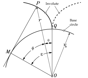
The planar involute of a circle is defined as the curve traced by a point P on a taut chord that unwraps from a circle, constituting the base circle of the involute. Figure 1 shows the basic definition of the involute curve and its related design parameters. Point P in Figure 1 is a point of an involute curve traced while it unwraps from base circle of radius rb. From Figure 1:
![]() Equation 1
Equation 1
so that:
 Equation 2
Equation 2 is the fundamental equation for the planar involute curve. Angle θ is known as the involute polar angle. Angle ε in Figure 1 is the involute roll angle, which is the angle whose arc on the base circle of radius unity equals the tangent of angle φ at a selected point on the involute. For the planar involute, angle φ equals the pressure angle when point P lies on the pitch circle.
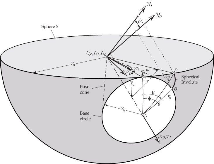
The spherical involute is the 3D counterpart of the planar involute of a circle. Similar to the definition of the planar involute, the spherical involute is defined as a 3D curve traced by a point P on a taut chord ![]() unwrapping from base circle of radius rb that lies on sphere S with origin at Os and radius r0 (see Figure 2). Point P in Figure 2 is a point of an involute curve traced while it unwraps from base circle of radius rb, obtained as the intersection between the base cone and the sphere of radius r0. The spherical involute is traced on the surface of the sphere S while point P unwraps over it from the base circle. Therefore, the arc length of the great circle
unwrapping from base circle of radius rb that lies on sphere S with origin at Os and radius r0 (see Figure 2). Point P in Figure 2 is a point of an involute curve traced while it unwraps from base circle of radius rb, obtained as the intersection between the base cone and the sphere of radius r0. The spherical involute is traced on the surface of the sphere S while point P unwraps over it from the base circle. Therefore, the arc length of the great circle ![]() is equal to the arc length of base circle, which is
is equal to the arc length of base circle, which is ![]() , and according to this:
, and according to this:
![]() Equation 3
Equation 3
Here, similar to the definitions for the planar involute curve, angle θ is the involute polar angle, and angle ε = (φ + θ) is the involute roll angle. Simplifying Equation 3:
![]() Equation 4
Equation 4
Considering again in Equation 4 that ε = (φ + θ), and solving for θ, we obtain:
![]() Equation 5
Equation 5
that can be considered as the function of the spherical involute. The following derivations will allow us to get angle φ as a function of angles γb and φ.
According to the principles of spherical trigonometry, arcs are represented by their angles [7]. Therefore, arcs ![]() ,
, ![]() ,
,![]() and can be represented by their angles φ, γb, and γ, respectively. By applying the law of cosines to the right spherical triangle OMP [7], the following relations can be derived:
and can be represented by their angles φ, γb, and γ, respectively. By applying the law of cosines to the right spherical triangle OMP [7], the following relations can be derived:
 Equation 6
 Equation 7
Similarly, by applying the spherical law of sine to the right angle spherical triangle OMP [7], additional relations can be obtained:
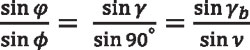 Equation 8
that yields the following equation for sin γ,
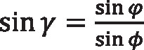 Equation 9
Substituting for cos γ and sin γ in Equation 7, according to Equations 6 and 9, we obtain:
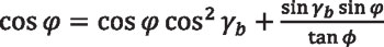 Equation 10
Upon rearranging Equation 10 and collecting terms, we obtain the following equation for angle φ as a function of angles γb and φ, namely:
 Equation 11
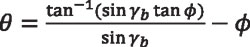
Using Equation 4 into Equation 11, we obtain:
![]() Equation 12
Equation 12
which can be considered the basic equation defining the spherical involute. If we substitute back ε = (φ + θ) and rearrange terms, we have:
 Equation 13
Equation 13, similarly to Equation 5, represents the spherical involute function, relating the polar angle θ with the azimuthal angle φ of point P by means of the base cone angle γb. This equation shows similarity with Equation 2, which defines the planar involute function.
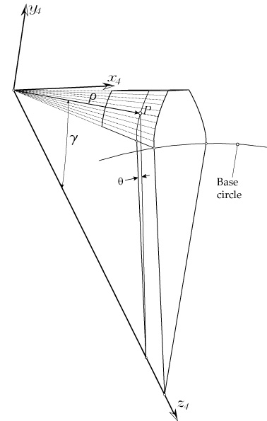
In order to get the curve traced by point P on the reference sphere, the coordinates of point P are needed. The coordinates of point P in coordinate system S1 (x1, y1, z1) can be derived as a function of angle γ (see Figure 2). Taking the tangent of both terms of Equation 4, we have:
![]() Equation 14
Equation 14
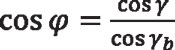
The tangent of φ can be obtained by using the values of sin φ and cos φ from Equations 9 and 6, namely:
![]() Equation 15
Equation 15
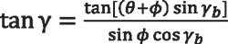
 Equation 16
so that:
![]() Equation 17
Equation 17
Equalizing Equations 14 and 17, the following equation can be obtained:
 Equation 18
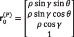
Position vector of point P in coordinate system S1 (x1, y1, z1) (Figure 2) is given by:
 Equation 19
The whole spherical involute profile can be drawn in coordinate system So (xo, yo, zo) by rotating coordinate system S1 (x1, y1, z1), around axis z1 in clockwise direction an angle θ (Figure 2), so that:
 Equation 20
Equation 20 will represent the right side profile of the straight bevel gear tooth surface. The left side profile of the straight bevel gear tooth surface can be obtained by rotating coordinate system S1 (x1, y1, z1), around axis z1 in counterclockwise direction an angle θ, namely:
 Equation 21
Indirect Definition
The indirect method is based on coordinate transformation and follows the works by Figliolini et al. [8] and Lee et al. [9]. By comparing the direct and indirect approaches, a good insight view of both approaches is obtained.
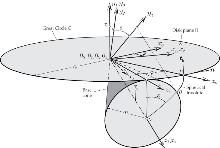
Figure 3 shows the schematic representation of the generation of the spherical involute profile using the coordinate transformation method. A spherical involute curve can be traced by a point P of the great circle C of the fundamental sphere S during the pure-rolling motion of its disk plane Π on the base cone of the bevel gear (Figure 3). By using coordinate transformation from coordinate system So (xo, yo, zo), in which the point P is defined, to coordinate system S3 (x3, y3, z3) which axis y3 is aligned with , where point Q represents the origin of the involute, lying on the base circle, the spherical involute profile can be obtained.
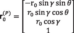
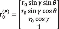
Point P is defined in coordinate system So (xo, yo, zo), which axis zo passes through point P, as follows:
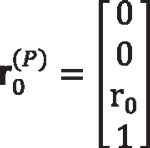 Equation 22
where:
r0 is the radius of the sphere in which the spherical involute profile is going to be traced.
The coordinate transformation matrices from coordinate system So (xo, yo, zo) to coordinate system S3 (x3, y3, z3) are written in the following:
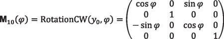 Equation 23
Notation “RotationCW(y0,φ)” means that the transformation matrix corresponds to a rotation of the coordinate system in clockwise direction (CW) around axis y0 an angle φ. Similarly:
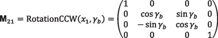 Equation 24
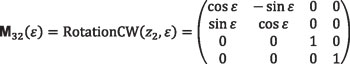 Equation 25
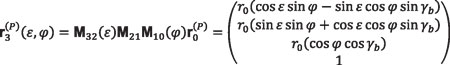 Equation 26
By applying the fundamental equation for pure rolling of disk plane Π on the base cone, given by Equation 4, and written here again for clarity:
 Equation 27
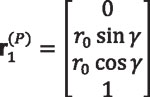
together with Equation 26, a point P on the involute will be perfectly defined in coordinate system S3 (x3, y3, z3) for any given angle ε. We recall that γb is the cone base angle that will be obtained directly from the initial design data. Equation 26 gives the coordinates of the right side of the spherical involute profile of the gear tooth surfaces at the sphere of radius r0. To obtain the left side profile, Equations 23 to 25 should be modified accordingly.
Determination of the Normal Vector
One advantage of the indirect method of determination of the spherical involute is that the normal and tangent vectors to the tooth profile can be derived easily. Determination of the normal to the gear tooth surfaces will be needed to perform tooth contact analysis. Figure 3 shows the unit normal and unit tangent vectors in coordinate system S0. The unit normal in coordinate system S0 is given by:
 Equation 28
and the unit tangent vector to the spherical involute profile at point P:
 Equation 29
Normal and tangent vectors to the spherical involute profile in coordinate system S3 (x3, y3, z3) are obtained by:
 Equation 30
 Equation 31
We recall that angles ε and φ are related by Equation 27, representing the condition of pure rolling of disk plane Π on the base cone. Matrices Lij are 3×3 submatrices of the corresponding matrix Mij, obtained by eliminating the last row and the last column. This results from the fact that the vector components (projections on coordinate axes) do not depend on the location of the origin of the coordinate system [10].
Definition of the Spherical Bevel Gear Tooth Surfaces
Gear Tooth Thickness
The tooth thickness tp for the to-be-generated bevel gear is considered as given. The standard tooth thickness is obtained by considering half of the angular pitch, namely:
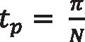 Equation 32
where:
N is the number of teeth of the gear.
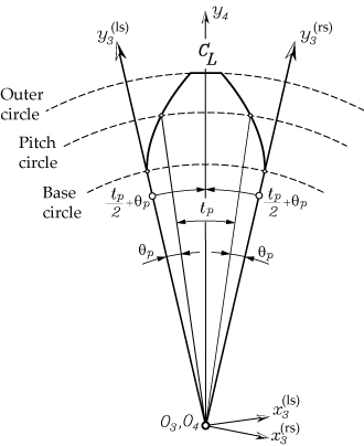
The required backlash is considered modifying tp accordingly. Figure 4 shows the additional coordinate transformation to obtain the involute profile in a coordinate system aligned with the center line of the gear tooth.
The transformation for the right side of the tooth profile is:
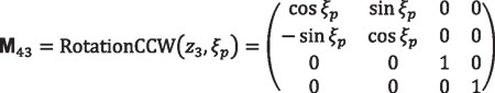 Equation 33
where:
ξp is equal to (tp/2)+θp as shown in Figure 4.
Angle θp is the polar angle when point P lies on the pitch cone. Similarly, for the left side, the coordinate transformation will be:
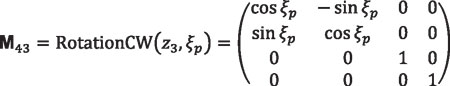 Equation 34
Determination of the Polar Angle at the Pitch Cone
The polar angle at the pitch cone, θ`p, can be determined by Equation 13, which expresses the polar angle θ as a function of angles γb and φ. For the planar involute profile, the azimuthal angle φ is equal to the pressure angle when P lies on the pitch cylinder. However, that statement cannot be extrapolated to the case of spherical gear when point P lies on the pitch cone. According to previous derivations (see Equation 11):
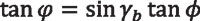 Equation 35
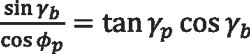
Also, according to previous derivations (see Equation 17):
 Equation 36
where γ = γp and φ = φp when P lies on the pitch cone. Equalizing the previous two equations:
 Equation 37
 Equation 38
 Equation 39
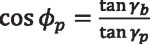 Equation 40
Equation 40 allows the azimuthal angle φp for point P lying on the pitch cone to be determined as a function of the base cone angle γb and the pitch angle γp. Once the azimuthal φp is known, the polar angle at the pitch cone can be obtained by using Equation 13, written here again for clarity, wherein φ = φp.
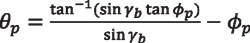 Equation 41
Determination of the Base Cone Angle
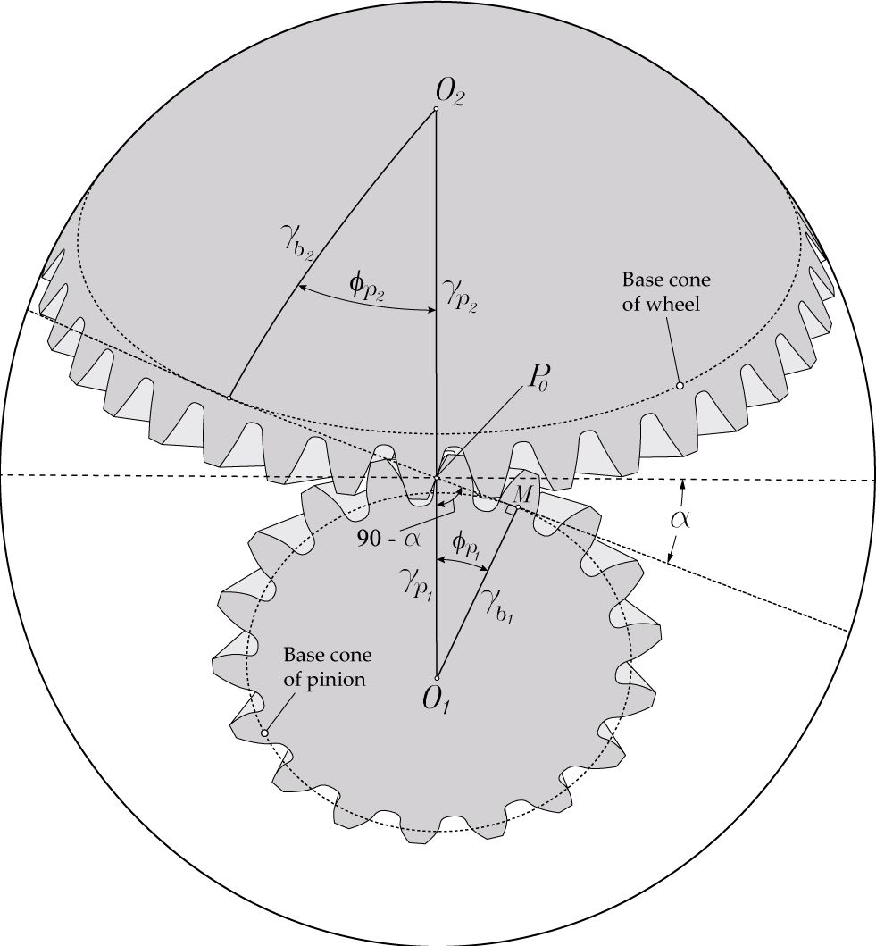
Figure 5 shows the pinion and the wheel of a spherical gear set in contact at point P0 located at the pitch cone. Subindex 1 refers to the pinion, and subindex 2 refers to the wheel. However, the relations derived here are valid for pinion and wheel, and the corresponding subindexes will not be included. Applying the spherical law of sine to the right angle spherical triangle O1MP0 [7], the following relations can be obtained:
 Equation 42
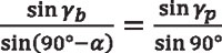
Considering that sin(90°− α) = cos α and sin 90° = 1:
 Equation 43
where α is the pressure angle.
The Spherical Involute Bevel Gear Tooth Surfaces
Figure 6 shows the gear tooth surface generated from the spherical involute profile traced on the outer reference sphere. Points on the spherical involute profile are projected toward the center of the sphere, and in this way, the gear tooth surfaces are generated.
The left side gear tooth surface, according to Equation 21, is given in terms of γ and θ as:
 Equation 44
where:
ρ is the radius of the sphere in which the point lies
γ is the zenith angle that can be determined by Equation 18
Radius ρ will vary between the inner pitch cone distance Ai and the outer pitch cone distance A0. The outer pitch cone distance is obtained from the pitch radius and pitch angle as:
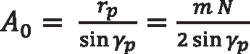 Equation 45
where:
m is the module
N is the number of teeth
γp is the pitch angle of the gear
The inner cone distance Ai is obtained as:
 Equation 46
where: Fw is the face width of the bevel gear, usually equal approximately to one-third of the outer pitch cone distance A0.
Face and Root Cone Angles
For spherical involute straight bevel gears, the addendum and dedendum coefficients will be used for determination of the face and root cone angles. The addendum coefficient is denoted here as ka and the dedendum coefficient as kd. Those coefficients will determine the addendum and dedendum heights at the outer section of the gear tooth surface by multiplying those values by the module of the gear.
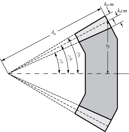
According to Figure 7, the face cone angle γf of the spherical involute bevel gear will be determined by:
 Equation 47
Similarly, the root cone angle γr is given by:
 Equation 48
where:
N is the number of teeth of the gear
γp is the pitch angle
ka is the addendum coefficient, usually equal to 1
kd is the dedendum coefficient, usually equal to 1.25
Modified Geometry for Localization of Contact
As mentioned before, the indirect definition of the spherical involute profile allows the gear tooth surfaces, their normal, and derivatives to be determined. Based on the indirect definition of the spherical involute profile, microgeometry modifications can be applied to the gear tooth surfaces for localization of contact and predesign of a parabolic function of transmission errors. The proposed gear tooth surface modification is based on changing angle φ in the coordinate transformation matrix given by Equation 23 by modified angle φ’ as follows:
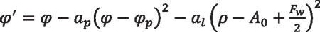 Equation 49
where:
ap is the parabola coefficient for profile crowning
al is the parabola coefficient for longitudinal crowning
Coefficient ap influences the maximum level of transmission errors. Coefficient al influences the localization of contact. Algorithms to find those coefficients based on the desired level of transmission errors and percentage of face width for contact patterns might be implemented based, for example, on the secant method or the Newton-Raphson algorithm. In this way, those parameters will be determined according to the desired conditions of meshing and contact.
Tooth Contact Analysis of Spherical Involute Bevel Gears
Computerized simulation of meshing and contact is based on the application of an enhanced algorithm for tooth contact analysis (TCA) and directed to the determination of the contact pattern and function of transmission errors.
The proposed enhanced algorithm for TCA is based on a rigid body hypothesis of contact of mating surfaces. Consequently, no elastic tooth deformation is taken into account for contact pattern determination. Basically, contact path determination is based on the ideas presented in Sheveleva’s work [11], according to which the relative position between pairs of contacting tooth surfaces is taken into account and the rotation of one of the members of the gear set is determined until contact is reached. Then, the contact pattern is determined, considering the locus of those points, which are positioned a relative distance between surfaces in contact given by a virtual marking compound thickness, usually equal to 0.0065 mm. Essentially, the described TCA algorithm is independent of the type of bearing contact between mating surfaces (point, line, or edge contact), does not require the solution of any system of nonlinear equations, and takes into account the effect of adjacent pairs of meshing teeth on the contact pattern.
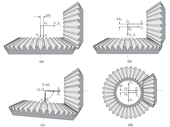
The errors of alignment considered for simulation of meshing and contact are:
- ΔA1 as the axial displacement of the pinion (Figure 8a)
- ΔA2 as the axial displacement of the wheel (Figure 8b)
- DΣ as the shaft angle error (Figure 8c)
- ΔE; as the minimum distance between axes (Figure 8d)
Finite Element Analysis
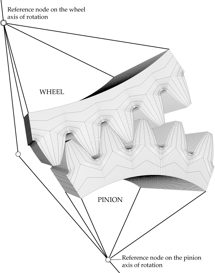
The finite element method has been used to perform stress analysis. Finite element models comprising five pairs of contacting teeth have been employed to avoid influence of the boundary conditions on the results. The model size consists of 190610 elements and 232352 nodes. Figure 9 shows the finite element model of a spherical involute straight bevel gear set. Gear active tooth surfaces have been defined as master surfaces, while pinion active tooth surfaces have been defined as slave surfaces. Three-dimensional solid elements of type C3D8I [12] have been used, being hexahedral first-order elements enhanced by incompatible deformation modes in order to improve their bending behavior. Pinion and gear material is steel defined with an elastic modulus of 210 GPa and Poisson ratio of 0.3.
Numerical Example
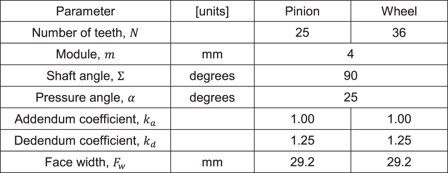
Table 1 shows the general design parameters of a spherical straight bevel gear set that has been used for testing the proposed geometrical approach.
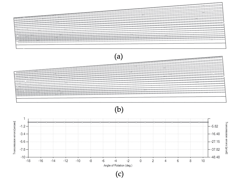
Firstly, Figure 10 shows the contact pattern and function of transmission errors for the case where pinion and gear are perfectly aligned. As expected, the contact pattern covers the whole active tooth surfaces of the pinion and gear, and there are no transmission errors. In this case, pinion and wheel are in lineal contact. This geometry is the perfect candidate for a plastic gear where the contact stresses have to be considerably reduced.
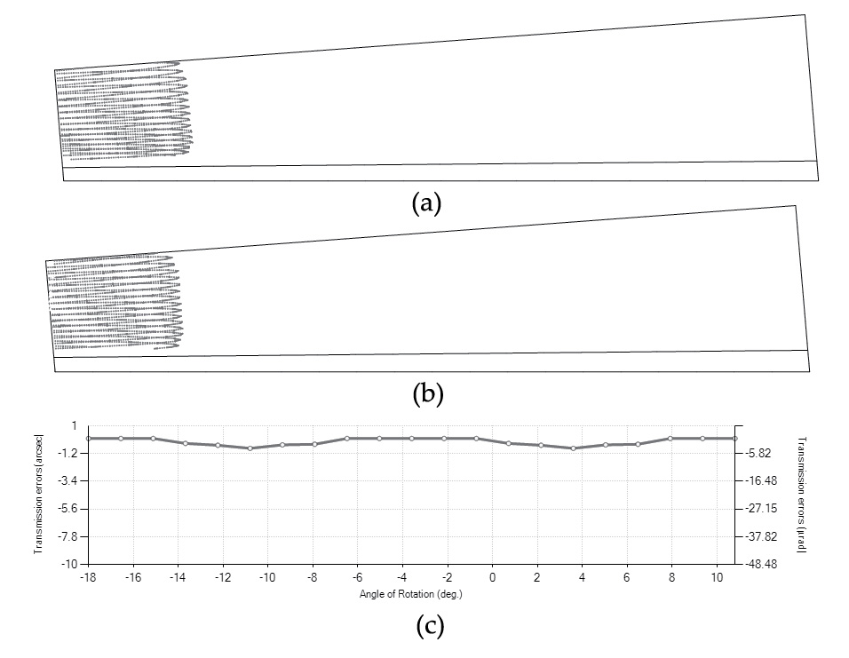
Bevel gear drives with intersecting axes are sensitive to changes of the minimum distance between axes ΔE. Figure 11 shows the contact pattern and function of transmission errors for the case where the minimum distance between the axis of the pinion and wheel pinion is ΔE = 0.075 mm. Although transmission errors are kept low, the contact pattern is shifted to the edge of the tooth surface profile, causing high contact stresses and contributing to the premature failure of the gear drive.
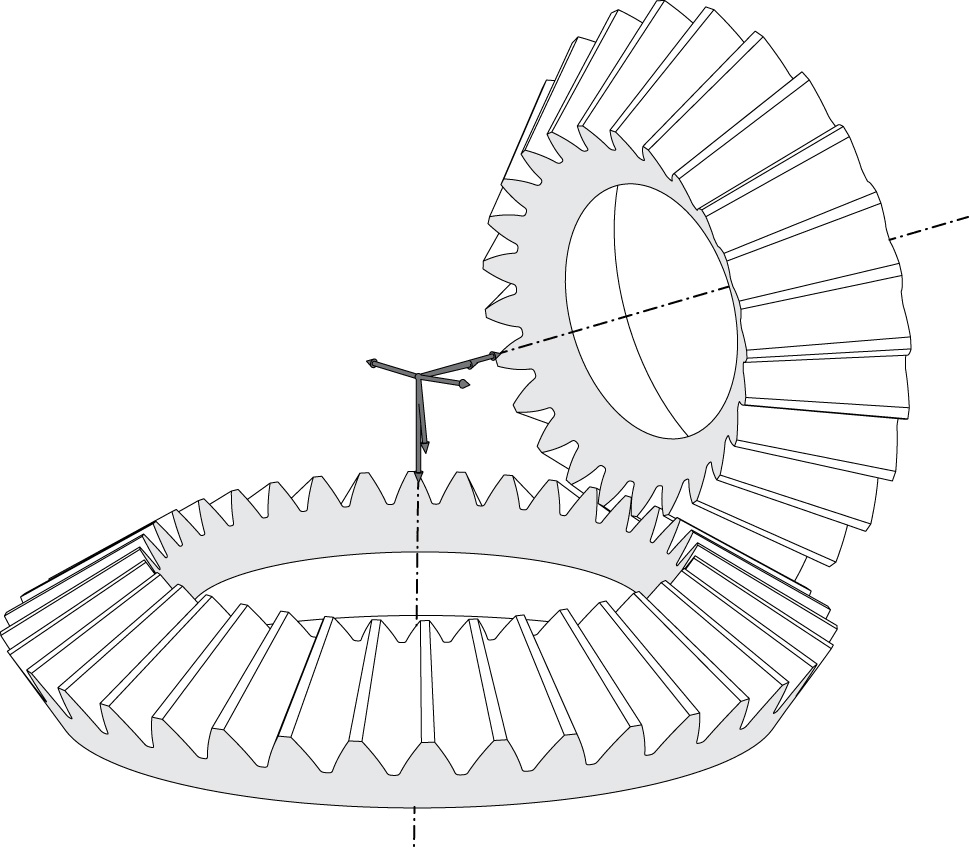
error ∆Σ = 2 degrees
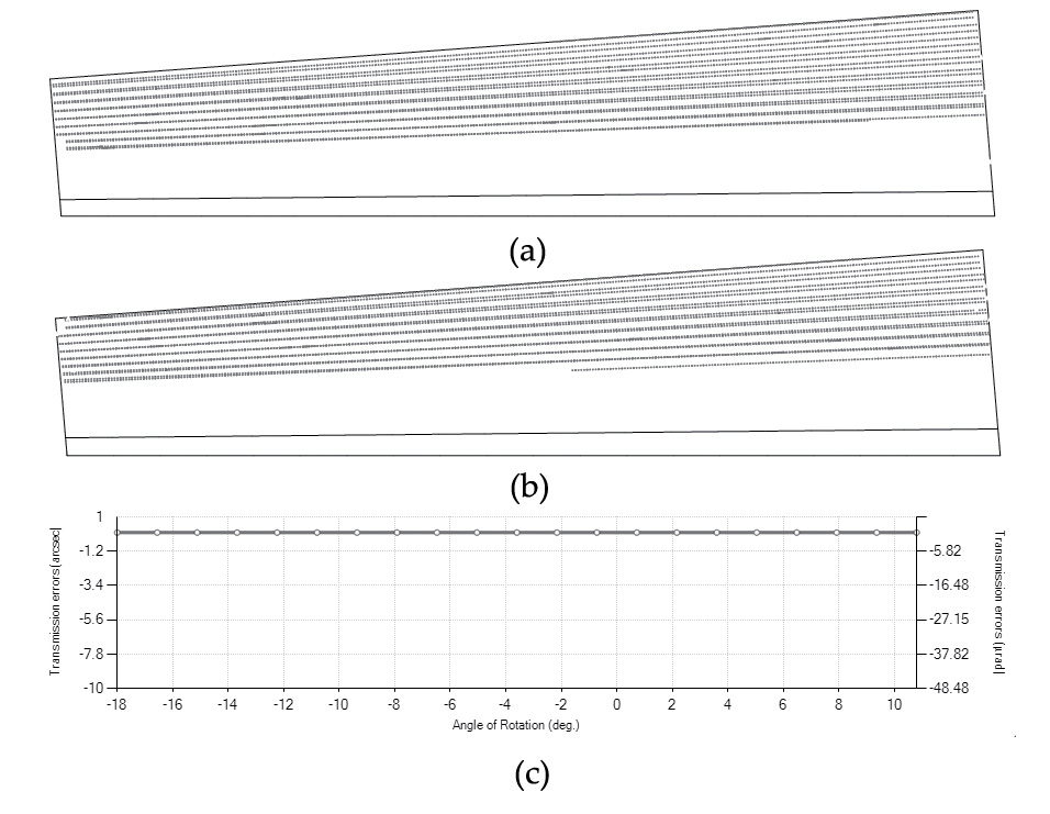
Figure 12 shows the bevel gear drive under an error of alignment ΔΣ =2 degrees, which is a huge error for a gear drive, and Figure 13 shows the contact pattern and function of transmission errors for this case. As shown in Figure 13, the gear drive keeps the lineal contact between pinion and wheel tooth surfaces, and the function of transmission errors is kept equal to zero. Similar to the case of involute cylindrical gears that are not sensitive to center distance error, spherical involute bevel gears are not sensitive to changes in the shaft angle. The limits on changes on the shaft angles are set by the conditions of having positive backlash and a contact ratio higher than 1.
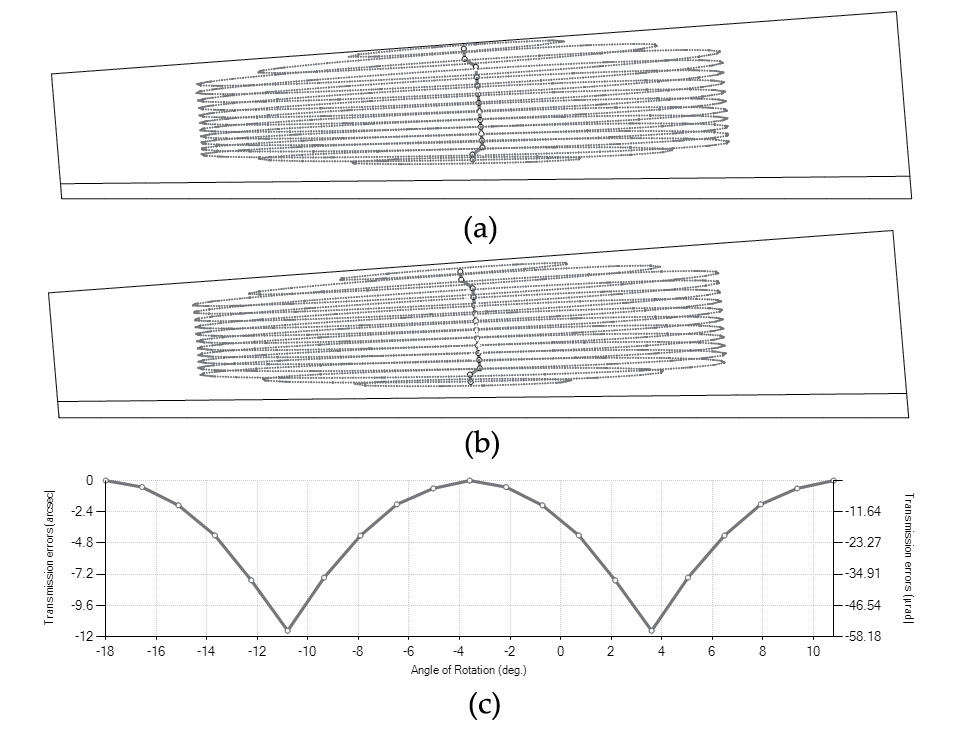
Application of surface modifications according to Equation 49 allows localizing the bearing contact and predesigning a parabolic function of transmission error to minimize the loaded function of transmission errors and provide a low level of noise and vibration of the gear drive. The optimized coefficients for profile crowning ap and longitudinal crowning al in Equation 49 are ap = 0.01 and al = 0.000001. Considering these values, the contact pattern and function of transmission errors shown in Figure 14 are obtained. This contact pattern is good for metal gears because it provides localized contact and a predesigned parabolic function of transmission errors. Profile crowning also helps to provide a smooth procedure of loading and unloading of the gear tooth surfaces in mesh.
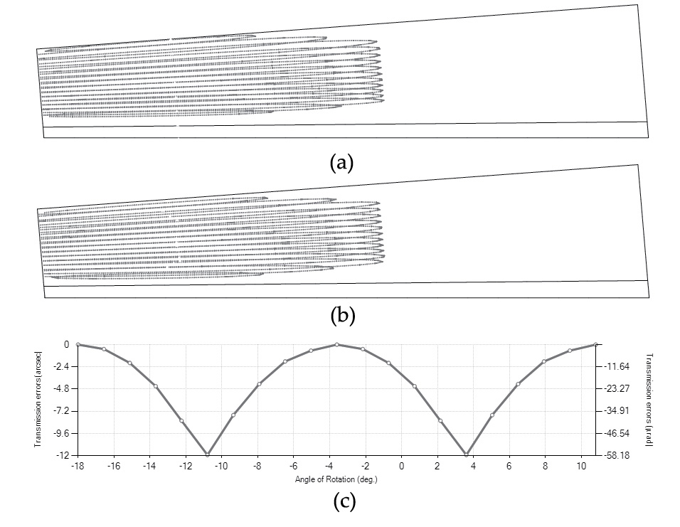
Figure 15 shows the contact patterns and function of transmission errors for the case of geometry modification and the influence of an error of alignment ΔE = 0.075 mm. The contact path is still inside the active tooth surface, avoiding, in this way possible, high stresses due to contacts all over the edge of the surfaces. Finite element analysis will give more information on the mechanical behavior of all cases of design analyzed.
A torque of 500 Nm has been considered for stress analysis. The previous four cases studied from the TCA point-of-view will be compared from the stress analysis point-of-view. The four cases of design are summarized in Table 2.
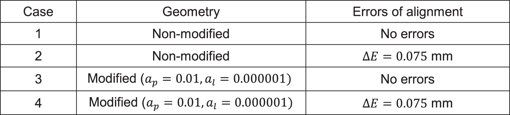
Figure 16 shows the evolution of maximum contact stresses on (a) the pinion and (b) the wheel tooth surfaces along two cycles of meshing for all cases shown in Table 2. The lowest contact stresses are obtained for Case 1 where no surface modifications and no errors of alignment are being considered. However, when errors of alignment occur and no surface modifications are provided (Case 2), contact stresses are high, and the failure of the gear drive may occur. Modification of the surfaces to localize the bearing contact slightly increment contact stresses along the cycle of meshing (Case 3) with respect to the case with no surface modification, but when errors of alignment occur (Case 4), contact stresses only experience a slight increase (see Figure 16). Here, all finite element models have been kept with the same number of elements and boundary conditions for all cases analyzed to cancel those errors, physical and numerical, associated with the finite element method among the considered cases of design and thus allowing the focus on the difference of stress levels.
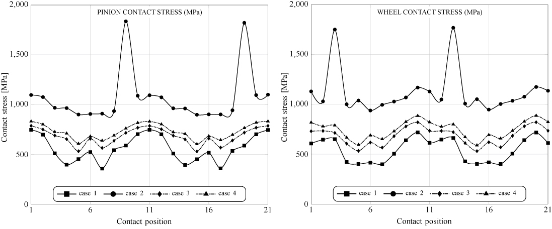
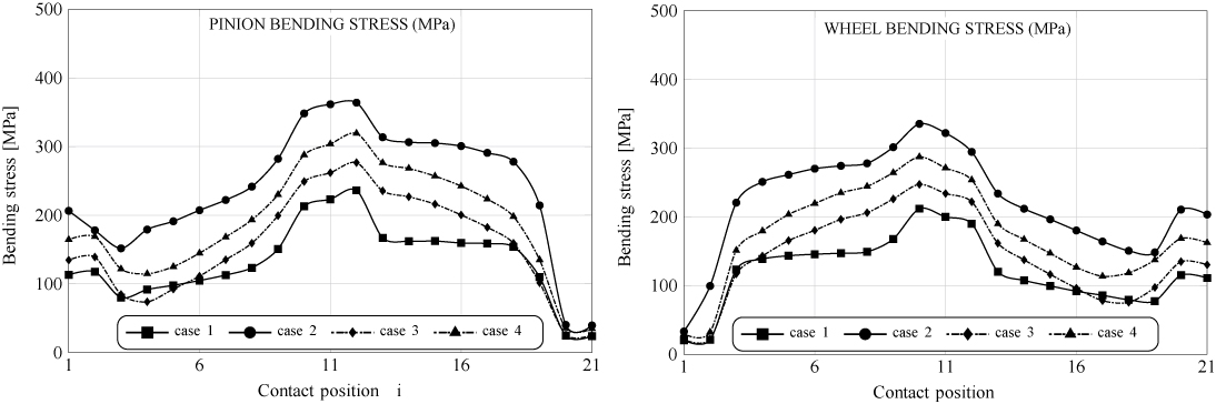
Figure 17 shows the evolution of bending stresses in the fillet of the pinion and wheel tooth surfaces along a cycle of meshing for all cases shown in Table 2. Again, the lower bending stresses are obtained for Case 1 with lineal contact and no errors of alignment. Higher bending stresses are obtained for Case 2 with lineal contact (no surface modification) and errors of alignment. Cases 3 and 4 show higher bending stresses than for Case 1 but always smaller stresses than Case 2, demonstrating that modification of geometry contributes effectively to making the gear drive not sensitive to errors of alignment and keeping the stresses low.
Conclusions
Based on the performed research work, the following conclusions can be drawn:
- The spherical involute profile, when considered as reference geometry for straight bevel gears, is providing excellent conditions of meshing and contact for plastic gears because it provides lineal contact between gear tooth surfaces and contributes to reduce contact stresses. Moreover, there are no transmission errors during the action of meshing.
- Straight bevel gears with spherical involute are not sensitive to changes in the shaft angle. The limits on variations of the shaft angle are set by the conditions of having positive backlash and a contact ratio higher than 1.
- An efficient way to incorporate microgeometry modifications into the design of spherical involute bevel gears has been proposed. When applied, microgeometry modifications, parabolic functions of transmission errors, can be predesigned and the contact localized, providing good conditions of meshing under the presence of errors of alignment.
References
- Kolivand, M. and Ligata, H. and Steyer, G. and Benedict, D. K. and Chen, J., 2015, “Actual Tooth Contact Analysis of Straight Bevel Gears,” Journal of Mechanical Design, 137(9).
- Radzevich, S. P., 2015, Dudley’s Handbook of Practical Gear Design and Manufacture, 2nd Ed., CRC Press, 2015.
- Stadtfeld, H. J., 2010, “Coniflex Straight Bevel Gear Manufacturing,” Gear Solutions, Aug., pp.40–55.
- Al-Daccak, M. J. and Angeles, J. and Gonzalez-Palacios, M. A., 1994, “Modeling of bevel gears using the exact spherical involute,” Journal of Mechanical Design, 116(2), pp. 364–368.
- Ligata, H. and Zhang, H. H., 2012, “Geometry Definition and Contact Analysis of Spherical Involute Straight Bevel Gears,” International Journal of Industrial Engineering and Production Research, 23(2), pp.101–111.
- Park, N. G., and Lee, H. W., 2011, “The Spherical Involute Bevel Gear; Its Geometry, Kinematic Behaviour and Standardization,” Journal of Mechanical Science and Technology, 25(4), pp.1023–1034.
- Harris, J. W. and Stocker, H., 1998, Handbook of Mathematic and Computational Science, Springer-Verlag.
- Figliolini, G. and Angeles, J., 2015, “Algorithms for Involute and Octoidal Bevel Gear Generation,” Journal of Mechanical Design, 127(4), pp.664–672.
- Lee, H. W. and Lee, K. O. and Chung, D. H., 2010, “A Kinematic Investigation of a Spherical Involute Bevel Geared System,” Proceedings of the Institutiion of Mechanical Engineers, Part C: Journal of Mechanical Engineering Science, 224(6), pp.1335–1348.
- Litvin, F. L. and Fuentes, A., 2004, Gear Geometry and Applied Theory, 2nd Edition, Cambridge Univeristy Press, New York.
- Sheveleva, G. I. and Volkov, A. E. and Medvedev, V. I., 2007, “Algorithms for analysis of meshing and contact of spiral bevel gears”, Mechanism and Machine Theory, 42(2), pp.198–215.
- ABAQUS/Standard User’s Manual, 2016, Providence, Rhode Island 02909-2499.


 general practice for CQI-9 and AMS2750E")


