


Regenerative combustion technology has many advantages such as fuel saving, high combustion efficiency and low emission, and it has been widely used for large-scale furnaces. However, when regenerative combustion technology is adopted for small-scale furnaces, many technical problems occur. In this article, a small-scale regenerative furnace with a heat load of 70-80 kW and primary air coefficient of 1.00-1.60 was designed. It was found that the flame shifts from bright pale blue with faint rotating streamlines to yellowish transparent without apparent streamlines and to bright and transparent eventually. When main burners work stably, the temperature inside the furnace rises rapidly at first, and then the temperature increases steadily and fluctuates periodically. The highest temperature in the furnace can reach about 1,300°C. As the reversing time increases, the temperature fluctuation becomes more dramatic and the highest temperature is higher. NOx concentrations at all measurement points are below 50 ppm. Heat-transfer efficiencies of each heat retainer show an increasing trend with the rise of the number of reversions. As reversing time increases, the heat-transfer efficiency shows a decreasing trend.
1 Introduction
Global natural gas consumption has increased dramatically since 2000, with an average annual growth rate of more than 2% over the past 10-plus years [1]. Carbon dioxide and emissions generated from combustion are crucial for global warming and environmental pollution [2,3]. Improving energy efficiency of fuels and reducing emissions are accepted solutions to adapt to the concept of sustainable development.
Among the downstream terminal consumption of natural gas, industrial production accounts for a large proportion. In China, industrial gas consumption accounted for a proportion as high as 69% in 2018 [4]. Most research of industrial furnaces focused on energy efficiency improvement, combustion efficiency increasing, waste-heat recovery, and new technology development. The relationship between waste-heat recovery and heat efficiency was studied by Hasanuzzaman et al. [5], and it was found that fuel consumption can be dramatically reduced by waste heat recovery technology. Also, reducing primary air coefficient and adapting flue gas recycling technology are beneficial for increasing air preheating temperature to improve the energy efficiency of furnaces [6]. Adding hydrogen into natural gas is also an effective method to improve energy efficiency and reduce emissions [7]. In the early 1980s, a regenerative waste heat recovery system, which can preheat air to 1,000°C, was developed by British Gas and Hotwork Development [8]. This technology increased waste heat recovery efficiency dramatically, and it is considered as a major breakthrough in this field. Regenerative combustion technology has achieved great success in energy saving and environmental protection.
The basic operation theory of regenerative combustion technology is that high temperature preheated air (800-1,000°C) is injected into the furnace, and oxygen concentration in the combustion area is quite low (2%∼21% O2%). In the meantime, fuel gas injected into the high temperature air, and waste heat is recovered effectively during combustion.
Compared with traditional combustion technology, regenerative combustion technology has many advantages such as fuel saving, high-combustion efficiency, and low emissions [9,10]. Most research has focused on heat-retainer characteristics, the combustion process, and NOx emission. Heat-transfer characteristics of heat retainers will affect the preheated air temperature, preheating time, and flue gas temperature and then it will affect reversing time, heat efficiency, and economic benefits. The dynamic change of temperature and flow velocity of heat retainers were calculated by Rafidi et al. [11], and heat storage and pressure dropped under different revering time, and heat loads were analyzed. A series of material-properties parameters were achieved through experiments on burner materials by Jiang et al. [12]. The unsteady heat flow of the spherical particle heat retainer was analyzed numerically, and design basis provided depended on it. Heat-transfer process and flow resistance characteristics of a honeycomb ceramics heat retainer were studied experimentally and numerically [13]. When regenerative combustion technology is adopted, there will be many differences from that of traditional combustion processes, such as low oxygen concentration, transparent flame, and temperature uniformity [14]. A mathematical model of the turbulent jet flow of high temperature preheated air and fuel gas was established by YANG et al. [15], and it was found that a flame with high preheated temperature and low oxygen concentration had a larger volume compared with traditional combustion technology. WANG et al. found that combustion temperature uniformity can be achieved more easily for lower oxygen concentration in preheated air and for a higher fuel gas temperature [16]. It was found by Mayrhofer et al. that local temperature peak in the reaction zone increases when heat input of the flameless burner is reduced [17]. Combustion research of full flue gas cycle tested on a 0.3 MW burner was carried out by Mao et al., and it was found that improving the jet flow velocity and adopting rotation flow can expand the combustion zone, reduce combustion temperature, and improve temperature uniformity [18]. Based on experiments on a regenerative furnace with three pairs of burners, comparison on emission and temperature uniformity of parallel and staggered combustion was carried out by Cho et al. [19]. They drew a conclusion that parallel combustion is beneficial to improving temperature uniformity and lowering CO emissions. Compared with traditional combustion processes, a HiTAC (High temperature air combustion) flame has a bigger reaction zone and can give off more heat radiation [20]. The regenerative combustion can partly avoid high temperature, which is beneficial for the uniformity of the temperature inside the furnace and for reducing NOx [21]. A simplified chemical reaction model was adapted to predict the mechanism in regenerative combustion by He et al. [22], and it was found that emissions can be reduced by a reasonable flow organization. Also, increasing the fuel gas temperature can be beneficial to reducing NOx emissions and can improve flow mixing [23]. Increasing the preheating temperature is an effective method to reduce CO emissions and improve combustion efficiency [24].
Regenerative combustion technology has been widely used for large-scale furnace to achieve the role of energy saving and environmental protection. However, when regenerative combustion technology is adopted for small-scale furnaces, there can be many problems.
Burners are generally set symmetrically in the furnace, so the short circuit situation of air or fuel flow can occasionally occur. At this time, air or gas from adjacent burners is discharged outside the furnace before combustion is complete. Besides, the fluctuation of pressure inside the furnace is more severe for a small-scale furnace. These problems make it hard to apply regenerative combustion technology on a small-scale furnace, and it is seldom studied by researchers. In this article, a small-scale regenerative furnace was designed. In order to improve heat radiation and increase uniformity of flame temperature, the main burner is constructed of a swirl burner and disk-flame nozzle. Flame structure and temperature shift inside the furnace were studied experimentally. The effect of reversing time on temperature inside the furnace was studied, and the difference of emissions at different measurement points was analyzed. In addition, heat transfer efficiency improvement methods were proposed through heat transfer analysis.
2 Experimental methodology
2.1 Test rig
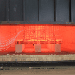
The structure of the furnace tested and discussed in this article is shown in Figure 1. The furnace is cuboid with a length of 3 meters, a width of 2 meters and a height of 1 meter. The walls of the furnace are made of iron with a thickness of 4 mm. The inner side of the walls is covered with aluminum silicate refractory fibers with a thickness of 300 mm to achieve the thermal insulation. The burners are set at two sides of the furnace, and the flame is maintained horizontally.
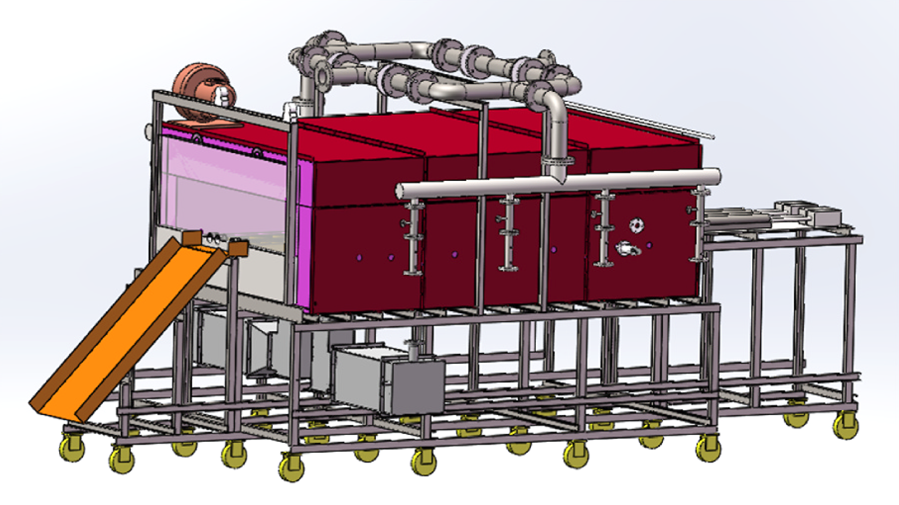
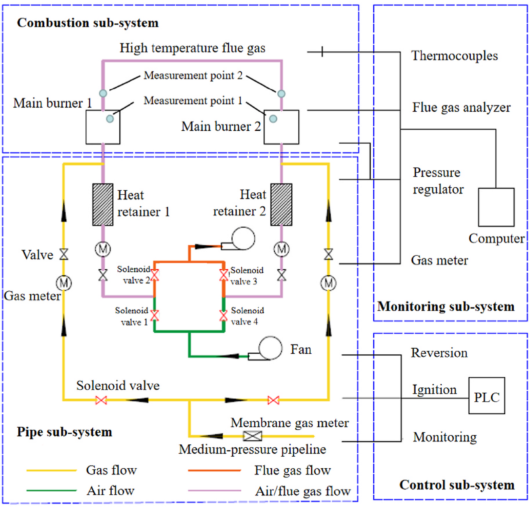
The test rig is comprised of four sub-systems: a pipe sub-system, a combustion sub-system, a monitoring sub-system, and a control sub-system, as shown in Figure 2.
The pipe sub-system involves natural gas pipes and air/flue gas pipes. Natural gas is introduced from the medium-pressure pipeline, and it then flows through the pressure regulator and membrane gas meter. After that, natural gas enters two pipes that connect to the two burners. In order to measure and control the gas flow, these two pipes are equipped with a solenoid valve, butterfly valve, and gas meter. In the pipe system, air and flue gas share the same pipes. Air and flue gas are driven by fans. The blower fan is set at the start of gas pipes for gas blowing, and the induced draft fan is set at the end of gas pipes for gas inducing. The flow of air and flue gas are controlled by four solenoid valves. The heat retainer is made of corundum-mullite, which has a honeycomb structure to effectively storage and release heat.
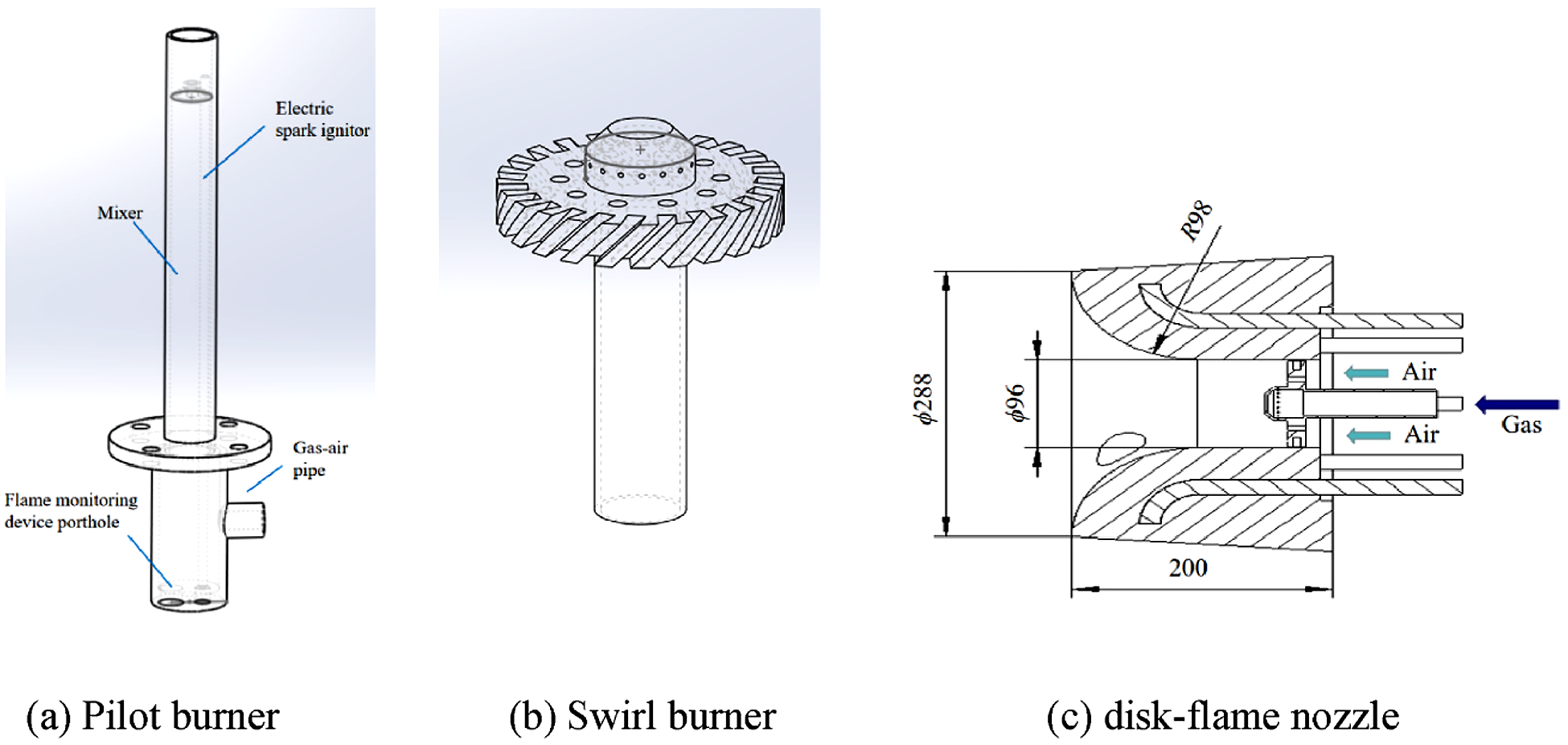
The combustion sub-system involves pilot burners and main burners. In order to ensure the combustion stability, each main burner is equipped with a pilot burner used for ignition and flame extinguishment protection of the main burner. The pilot burner is ignited by an electric spark ignitor. After the pilot burner is stably working, the main burner is ignited by it. The pilot burner and the main burner work together. The structure of the pilot burner is shown in Figure 3a, which includes a gas-air pipe, a mixer, an electric spark ignitor, and a flame monitoring device porthole. To improve heating capacity, the main burner is constructed by swirl burner (shown in Figure 3b) and disk-flame nozzle (shown in Figure 3c). The angle of the swirl vane of the swirl burner is 45°. There are 40 spouts in total with a diameter of 1.5 mm, and spouts for air and gas are 24 and 16 respectively. The gas-air mixture diffuses in a fan shape in the disk-flame nozzle, and after ignition, a disk flame appears.
The monitoring subsystem involves the measurement of temperature, flow rate, and flue gas composition. K-type thermocouples are usede for measurements of initial air temperature, preheated air temperature, and flue gas temperature before and after heat retainer. Five S-type thermocouples are used for temperature measurement inside the furnace. The flow rate of gas is monitored by a diaphragm gas meter, and the flow rate of air and flue gas are monitored by a Pitot pipe and differential pressure sensor. The composition of flue gas includes O2, CO2, CO, N2, NO, NO2, and it is sampled by the flue gas analyzer. The primary air coefficient is calculated by gas composition, which is:
 where, α is the primary air coefficient; O2‘ is the O2 volumetric concentration in dry flue gas; RO2‘ is the volumetric concentration of three-atom gas in the dry flue gas.
The control sub-system controls the test rig automatically by a programmable logic controller (PLC). The monitored temperature and flame condition are used for control strategy. The control operations include a valve opening, fan starting, and igniting. The flow direction of air and flue gas in the pipes is decided by the openings of the valves, which are controlled in this system. When burner 1 works, valve 1 and valve 3 open, and valve 2 and valve 4 close. Air flows to heat retainer 1 through valve 1, and then the heat stored in heat retainer 1 releases, which leads to the increase in air temperature. After that, preheated air flows into burner 1 and mixes with gas for combustion. Flue gas generated by burner 1 flows in the furnace, and then flows to heat retainer 2 via burner 2. At this time, flue gas transfers heat toward the heat retainer, and then low-temperature flue gas is discharged by the fan via valve 3. When burner 2 works, the working procedure is the same, so this detailed introduction is omitted. Afterwards, the flow of air and flue gas can be changed by changing the mode of valve 1, valve 2, valve 3, and valve 4, and then the circulation of combustion and heat regeneration is achieved.
2.2 Test procedure
After the reversing time is set in the PLC, the fans start to purge the pipes. The pressure of gas and air are tested within normal limits, and then the pilot burners are ignited. The gas valve for the main burner is open, and then the main burner is ignited. The gas flow is modified by valves to achieve the heat-load of 70-80 kW. The air flow is also modified by valves to achieve the main burner primary air coefficient of 1.00-1.60. Afterwards, the two main burners operate alternatively. The temperatures are collected and recorded, and the flame structures are photographed. When the temperature inside the furnace is stable, flue gases are sampled twice for 1 minute each and analyzed by the flue gas analyzer. Finally, the reversing time is changed, and the above procedures are repeated.
3 Results and discussion
3.1 Flame structure
The change of flame structure during the experiment is shown in Figure 4. Figure 4a shows the flame structure when the furnace works for 3 minutes. At this time, the temperature of preheated air and the temperature inside the furnace are quite low, so the flame is bright pale blue. The faint rotating streamlines inside the flame can be seen, which diffuses uniformly from the outlet of the flared burner brick and creates the extended flame surface. As the heat release from combustion continues, the pale blue fades from the flame. After half an hour, the flame is yellowish and transparent, as shown in Figure 4b. Additionally, streamlines of the flame are no longer apparent. At this time, the increase of the temperature of preheated air and the temperature inside the furnace strengthens the flame intensity, resulting in the change of flame structure.
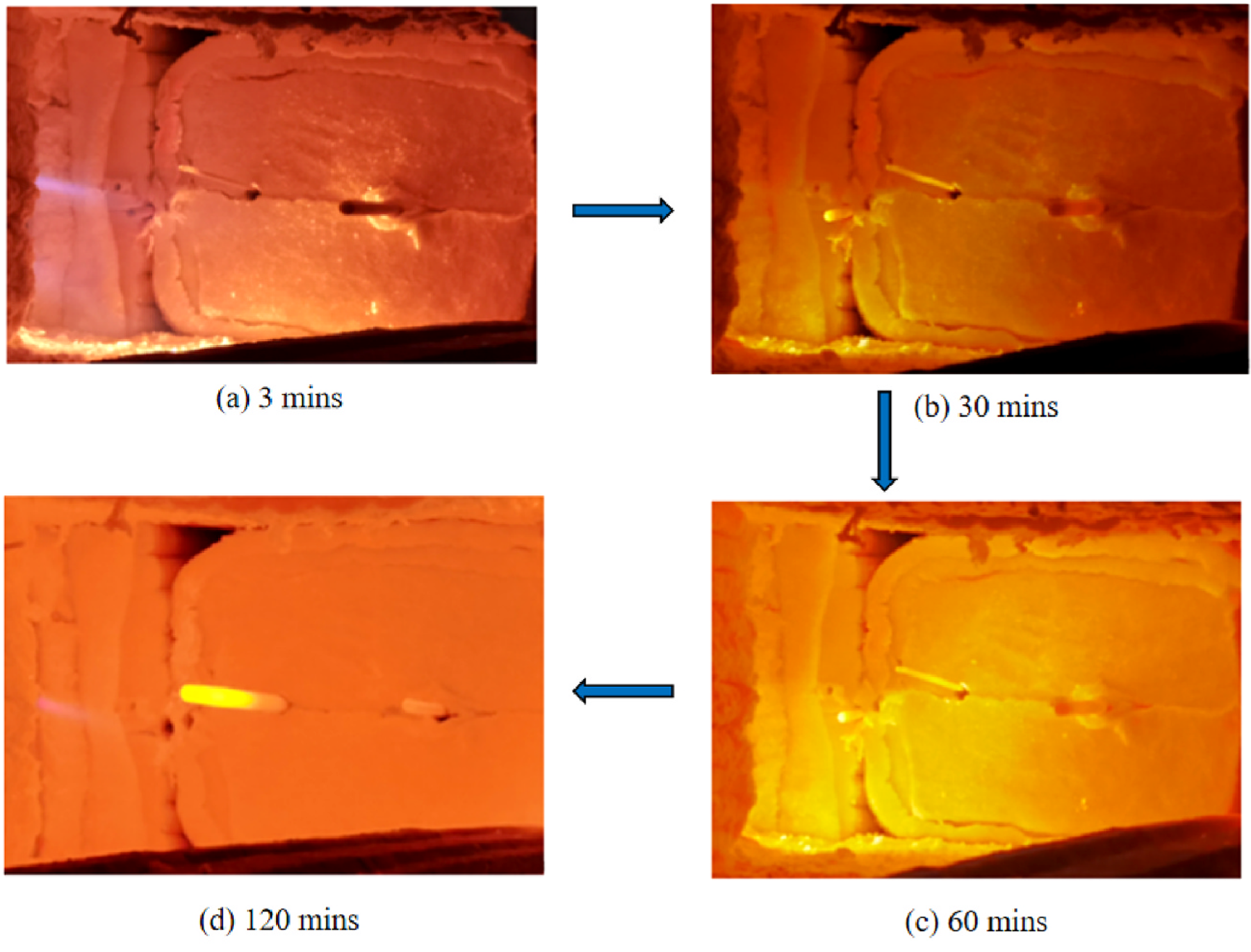
As the burner continues to work, the flame intensity increases. After an hour, the flame is bright and transparent, shown in Figure 4c. Continuously scoured by the high temperature flow and radiant heat by high temperature flame, the inner wall of the furnace is also bright yellow. The bright flame is formatted by the decomposition of alkane in natural gas under high temperature. Tiny suspended carbon particles generated by the decomposition are of high blackness, which means the radiation of the flame is strengthened. When the furnace works for more than 2 hours, the flame becomes transparent, shown in Figure 4d. The inner wall of the furnace is deep orange, and a strong burning sensation can be felt at the furnace door. At this time, the heating area in the furnace maintains high temperature uniformly because of the long heating time and the high temperature of tje preheated air.
3.2 Temperature shift
Taking the reversing time of 60 seconds as an example, the temperature shift during the working process of the furnace is analyzed, shown in Figure 5. Measurement point 1 is near the tip of the flame of the main burner. Measurement point 2 is set at the downstream of the flue gas, which is considered as the temperature of the heating area in the furnace.
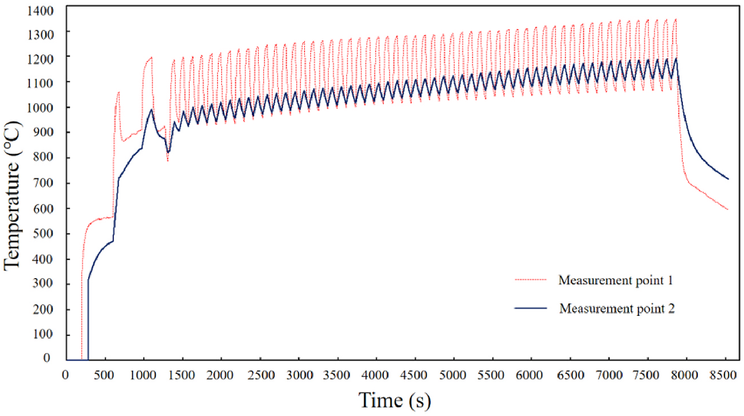
As shown in Figure 5, when the main burner works stably, the temperature inside the furnace rises rapidly and reaches more than 900°C in 10 minutes. The irregular temperature fluctuation at the initial stage is because the working condition of the burners is controlled manually at that time, which leads to the unfixed reversing time. The temperature inside the furnace and the temperatures of the thermal-insulation layer and the furnace wall are quite low. Therefore, when high temperature flue gas rushes, the gas flow in the furnace is unstable, which is also the reason for temperature fluctuation. After a preliminary adjustment setting, the control mode is set to be in automatic mode, and the reversing time is set to be 60 seconds. In this stage, temperatures of each measurement point fluctuate regularly. As the running time of the furnace increases, temperatures of each measurement point rise steadily. When the running time reaches 2 hours, the temperature of measurement point 1 reaches 1,350 °C, and that of measurement point 2 is 1,200°C. At this time, the temperature inside the furnace is high and uniform. When the furnace is stopped at two and a half hours, temperatures of each measurement point drop rapidly and then decreases gradually in a relatively high temperature range.
3.3 Reversing time
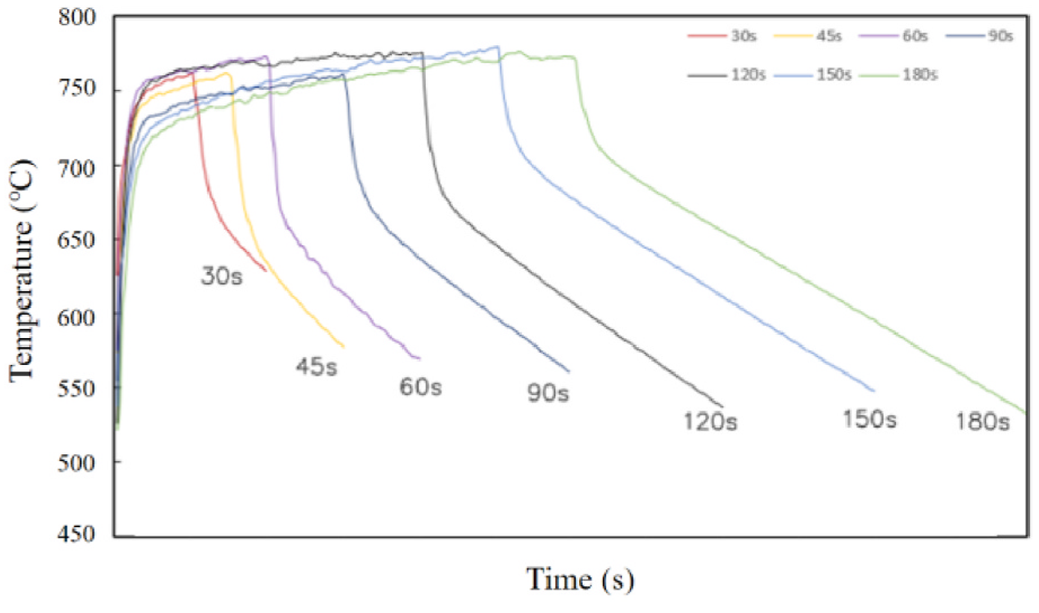
As an important operating parameter for reversed regenerative burners, the reversing time is crucial to the heat-exchange efficiency of the heat retainer, temperature fluctuation inside the furnace, and combustion condition. In order to fully take advantage of the regenerative burners, the reversing time needs to be appropriate for a certain furnace structure and burner-heat intensity. Therefore, temperature fluctuation under different a reversing time is discussed below. The temperature shifts in the heating zone of the furnace for the main burner revering time of 30 seconds to180 seconds are shown in Figure 6.
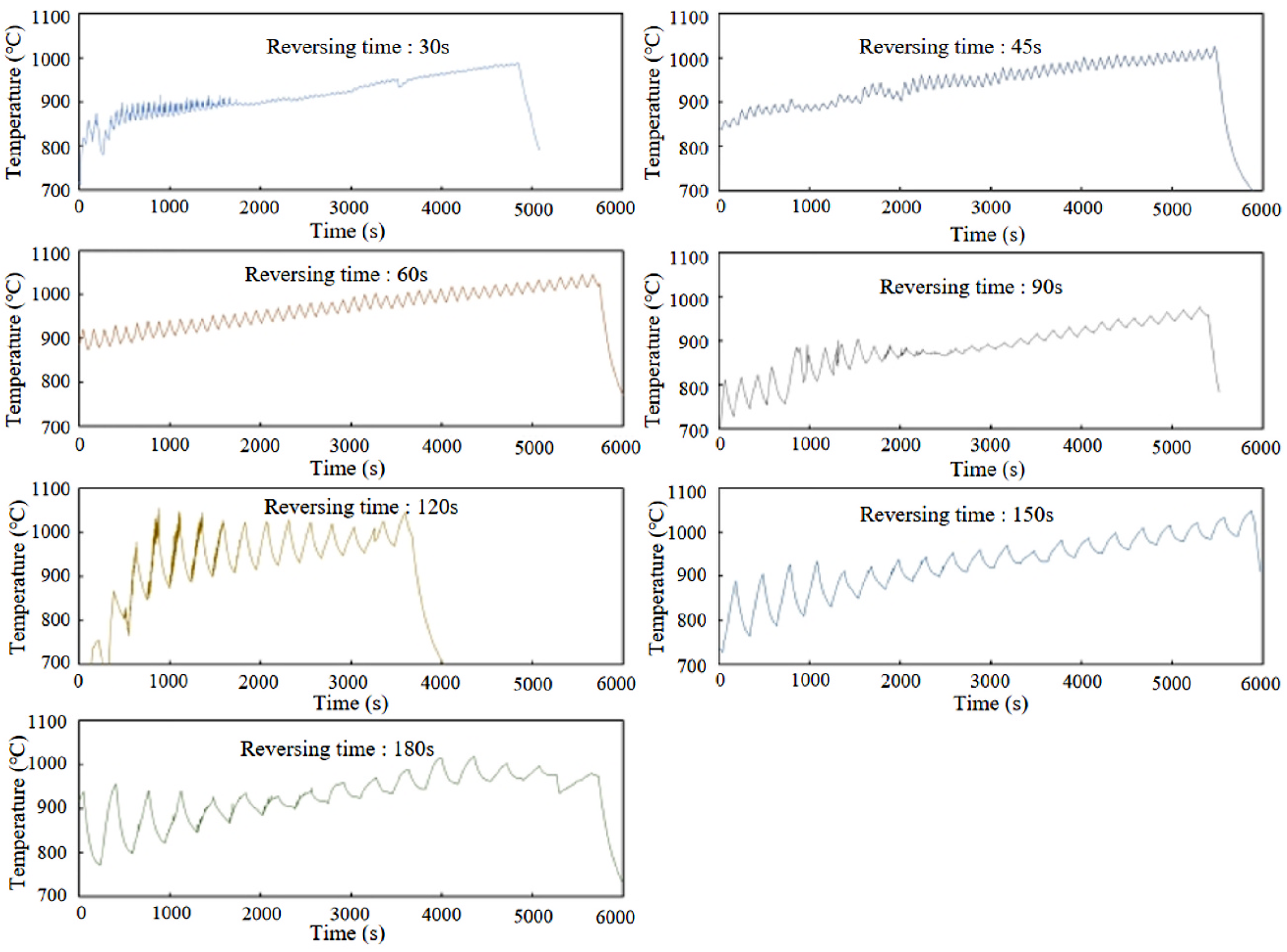
It can be seen in Figure 6 that, as the reversing time increases, the temperature fluctuation becomes more dramatic, which means that, during the temperature rising period, the difference between the peak and valley temperature in each reverse period increases. Although the temperature fluctuation differs under different reversing time, all the temperatures increase steadily. Also, it can be seen that, if the reversing time is longer, the highest temperature that can be reached is higher. This can be explained in that frequent reversion will increase the interruption times of the combustion, which has an effect on the heating capacity during the initial stage for heat storage. Also, the temperature increasing speed will decrease under a short reversing time for the reason above. This effect will be weakened with the increase of the running time. It can be known that, when the furnace works in the heat balance stage for a long time, the temperatures are close for different reversing time. Therefore, different reversing times should be adopted for different heating periods.
3.4 Pollution
The environmental estimation of combustion devices mainly focuses on the flue gas composition. One of the advantages of regenerative combustion is low NOx pollution. The uniform distribution of oxygen in the furnace avoids the appearance of partly high temperatures and thus the generation of thermal NOx reduces.
Four flue gas measurement points are selected for analyzing, shown in Table 1. The measurement point “Flue pipe” is set right behind the heat retainer. It can be seen from Table 1 that flue gas compositions at the flame zone are different for different working conditions, which leads to the difference of excess oxygen. But oxygen concentration in the whole furnace is under 8.5%, which is quite low for a furnace. The measurement point “Heating zone 1” and “Heating zone 2” are close to the furnace door, so the cold air penetration leads to higher excess oxygen concentration compared with the flame zone. The uniform temperature field of regenerative combustion technology dramatically reduces the generation of thermal NOx, which is below 50 ppm for all measurement points.

3.5 Heat transfer analysis
As one of the most important parts of regenerative combustion, the performance of heat retainer is crucial for the whole system. Only when the heat retainer matches burners well can the furnace work efficiently. The heat-transfer process of the heat retainer is analyzed below, including its relationship with reversing time and the number of reversions. Considering flue gas leakage and heat loss in the heat transfer process, the heat transferred from high temperature flue gas to heat retainer cannot be totally absorbed by preheated air. Therefore, heat-transfer efficiency is adopted to represent the heat-transfer capacity during the heat-transfer process, which is:
 where, η is the heat-transfer efficiency; T is the reversing time, s; τ is the working time, s; M is the mass flow rate, kg/s; Cp is the specific heat capacity, J/kg•°C; t is the gas temperature, °C. The subscripts “a” and “fg” represent air and flue gas, respectively. The subscripts “in” and “out” represent the inlet and outlet gas, respectively.
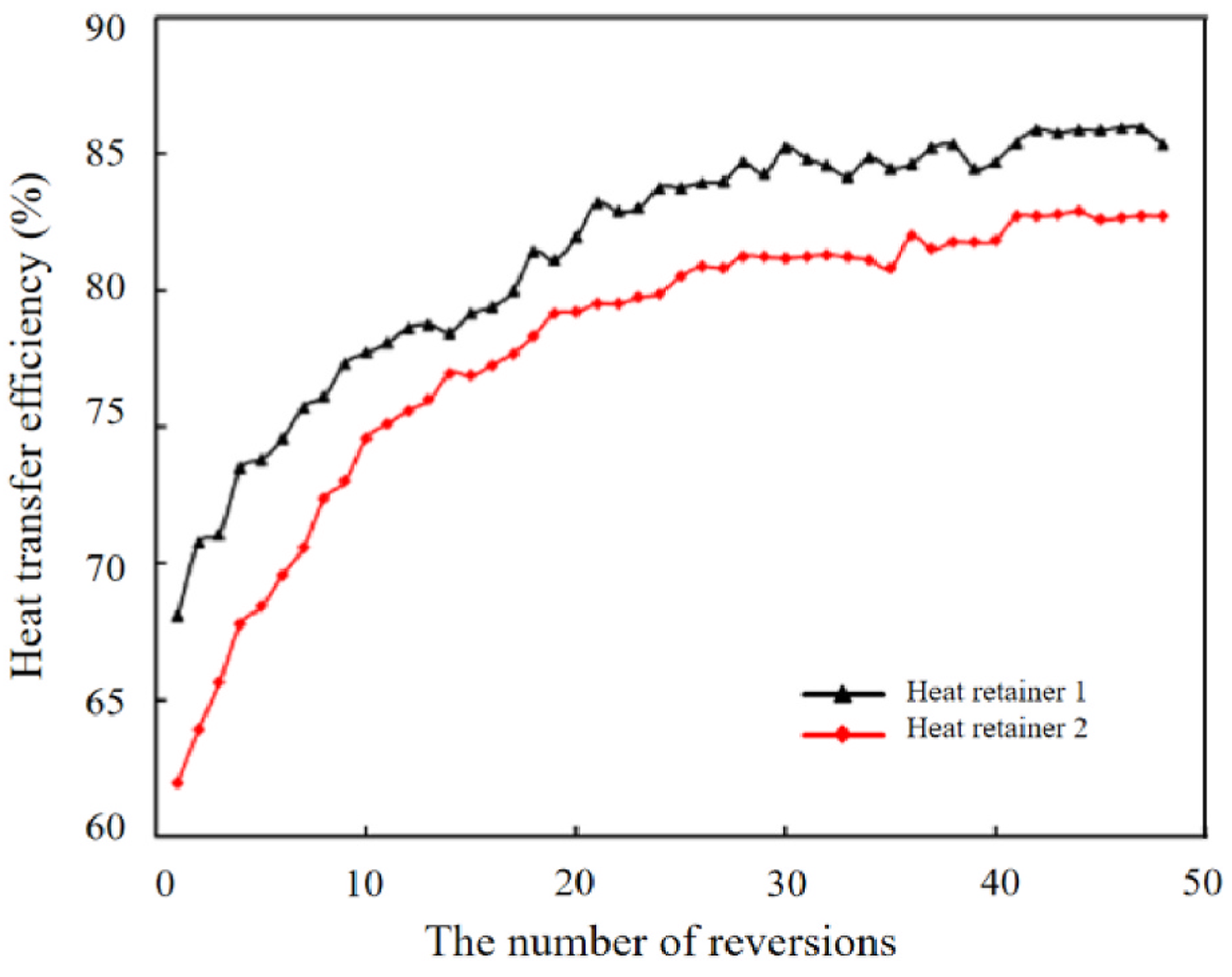
The calculated heat-transfer efficiency is the ratio of the heat absorbed by air from the heat retainer and the heat released by the flue gas to heat retainer in one reverse period. The value represents the heat-absorption capacity of the heat retainer and the heat exchange capacity of the heat-retainer chamber. Taking the reversing time of 30 seconds as an example, the heat-transfer efficiency of the heat retainer in each reversion period for the first 50 periods is analyzed, as shown in Figure 7. It can be known from Figure 7 that the heat-transfer efficiency of each heat retainer shows an increasing trend with the rise of the number of reversions. When the number of reversions reaches 40, the increase of the heat-transfer efficiency is relatively slow and fluctuates at a certain value. The heat-transfer efficiency is affected by many factors, such as physical properties of the heat retainer, heat intensity, flow rate, reversing time, and running time. At the beginning, the pipes are still cold and the temperature of the gas flow inside them is not high. At this time, the heat retainers are in a period of heat absorption. With the increase of the running time, the temperature of the heat retainer rises and heat transfer from the flue gas to heat retainer decreases. Therefore, the heat-transfer efficiency increases in this process. However, there is a limit to the heat absorption of the heat retainer. After the furnace has been running for a while, heat retainers will store a large amount of heat with a high temperature. In each reversion period, most heat transferred from the flue gas to the heat retainer will transfer to air. At this time, the heat transfer efficiency of the heat retainer stabilizes at a high level.
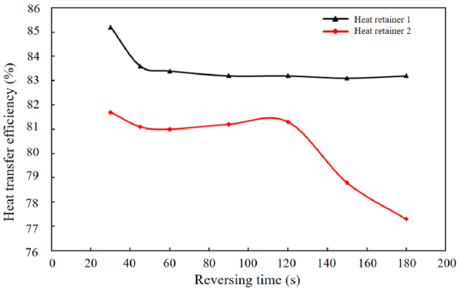
The heat-transfer efficiency of the two heat retainer chambers in a steady stage for a reversing time of 30-180 seconds is shown in Figure 8. There is a limit for a heat retainer to absorb heat. So, when the heat of the high-temperature flue gas continuously releases to the heat retainer, the heat retainer will be saturated eventually. Then the heat will flow into the environment by flue gas and heat exchange from the furnace wall. If the working condition of the burners are not reversed, heat will not be used efficiently. These are the reasons why the heat-transfer efficiency of the two heat-retainer chambers shows a decreasing trend with the increase of reversing time. As a result, a short reversing time is beneficial to heat-efficiency improvement.
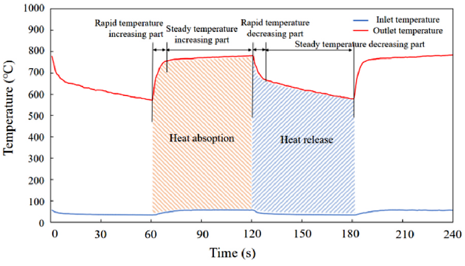
The temperature change at the outlet of the heat retainer in a reversing period for different reversing time is shown in Figure 9. The reversing period starts with the high temperature flue gas flowing into the heat retainer after a reversion. And the reversing period ends before the high-temperature flue gas flowing into the heat retainer for another reversion. Heat absorption and release of the heat retainer in a reversion period are shown in Figure 10. The heat absorption and release periods are divided in time according to the speed of the heat exchange. It can be seen that the highest temperatures at the outlet of the heat retainer for different reversing times are close, which are about 770°C. The heat exchange process of the heat retainer can be divided into a rapid-temperature-shift part and a steady-temperature-shift part. It also can be seen from Figure 9 that time for a rapid-temperature-shift part is close for different reversing times. Therefore, the time for a rapid-temperature-shift part increases with the rise of the reversing time, leading to a higher ratio in the reversing period. In a steady-temperature-increasing part, the difference between the temperature of the inlet and outlet is large for the heat-absorption process. At this time, the heat transfer in unit time is more than that of the rapid-temperature-increasing part. Therefore, heat transferred from the flue gas to the heat retainer in unit time increases with the rise of the reversing time. And for the heat-release process, the difference between the temperature of the inlet and outlet is small for a steady-temperature-decreasing part. At this time, the heat transfer in unit time is less than that of the rapid-temperature-decreasing part. Therefore, heat transferred from the heat retainer to air in unit time decreases with the rise of the reversing time. As a result, the increasing reversing time will lead to the drop of the heat efficiency of the heat retainer.
4 Conclusions
In this article, a small-scale industrial furnace with regenerative disc-flame burners with a heat load of 70-80 kW and primary air coefficient of 1.00-1.60 was designed and tested. Flame structure, temperature shift, emission, the effect of reversing time and heat transfer process were analyzed. Main conclusions are summarized as:
1. With the rise of temperature of preheated air and temperature inside the furnace, the flame structure shifts from bright pale blue with faint rotating streamlines to yellowish and transparent without apparent streamlines and to bright and transparent eventually.
2. When the main burner works stably, the temperature inside the furnace rises rapidly, and then the temperature increases steadily and fluctuates periodically. The highest temperature can reach about 1,300°C.
3. As the reversing time increases, the temperature fluctuation becomes more dramatic and the highest temperature can be reached is higher. A different reversing time should be adopted in a different heating period.
4. The oxygen concentration in the whole furnace is very low and uniform, which avoids the appearance of partly high temperatures and reduces the generation of thermal NOx. NOx concentration at all measurement points is below 50 ppm.
5. Heat-transfer efficiency of each heat retainer shows an increasing trend with the rise of the number of reversions. When the number of reversions reaches a certain value, the increase of heat-transfer efficiency is relatively slow and fluctuates at a fixed value. As reversing time increases, the heat-transfer efficiency shows a decreasing trend, so a short revering time is beneficial to heat-efficiency improvement.
Declaration of competing interest
The authors declare that they have no known competing financial interests or personal relationships that could have appeared to influence the work reported in this paper.
Data availability
No data was used for the research described in the article.
References
- B.P. Company; “BP Statistical Review of World Energy[R]”; (2022); https://www.bp.com/en/global/corporate/energy-economics/statistical-review-of-world-energy.html.
- Intergovernmental panel on climate change. “Climate change 2014: synthesis report.” https://www.ipcc.ch/site/assets/uploads/2018/05/SYR_AR5_FINAL_full_wcover.pdf.
- PBL Netherlands Environmental Assessment Agency. “Trends in global CO2 and total greenhouse gas emissions.” https://www.pbl.nl/en/publications/trends-in-global-co2-and-total-greenhouse-gas-emissions-2020-report.
- CNPC Economics & Technology Research Institute; “Energy Outlook of the World and China in 2050[M]”; (2018).
- M. Hasanuzzaman, R. Saidur, N.A. Rahim; “Analysis of Energy and Exergy of an Annealing Furnace”; Applied Mechanics and Materials (2012), p. 1471.
- C.-L. Lee, C.-J.G. Jou; “Saving fuel consumption and reducing pollution emissions for industrial furnace”; Fuel Process. Technol., 92 (12) (2011), pp. 2335-2340.
- S.-C. Hsieh, C.-J.G. Jou; “Using hydrogen-rich multifuel to improve energy efficiency and reduce CO2 emission for high-energy furnace”; Environ. Prog. Sustain. Energy, 28 (1) (2009), pp. 83-88.
- J.A. Wunning, J.G. Wunning; “Flameless oxidation to reduce thermal no-formation”; Elsevier, 23 (1) (1997).
- R. Weber, A.K. Gupta, S. Mochida; “High temperature air combustion (HiTAC): how it all started for applications in industrial furnaces and future prospects”; Appl. Energy (2020), p. 278.
- P. Li, J. Mi, B.B. Dally, et al.; “Progress and recent trend in MILD combustion”; Sci. China Technol. Sci., 54 (2) (2011), pp. 255-269.
- N. Rafidi, W. Blasiak; “Thermal performance analysis on a two composite material honeycomb heat regenerators used for HiTAC burners”; Appl. Therm. Eng., 25 (17–18) (2005), pp. 2966-2982.
- F. Jiang, J. Fanzhi, K. Jianyi, et al.; “Nonlinear numerical simulation of service behaviour of regenerative burner under multiple thermal shocks”; J. Phys. Conf., 1637 (1) (2020).
- P.M. Park, H.C. Cho, H.D. Shin; “Unsteady thermal flow analysis in a heat regenerator with spherical particles”; Int. J. Energy Res., 27 (2) (2003), pp. 161-172.
- K. Kang, S.-K. Hong, D.-S. Noh, et al.; “Heat transfer characteristics of a ceramic honeycomb regenerator for an oxy-fuel combustion furnace”; Appl. Therm. Eng., 70 (1) (2014), pp. 494-500.
- W.-H. Yang, S.-J. Jiang, T.-C. Hsiao, et al.; “Numerical simulation of high temperature air combustion flames properties”; J. Cent. S. Univ. Technol., 7 (3) (2000).
- A.-H. Wang, J.-J. Cai, G.-W. Xie; “Numerical simulation of combustion characteristics in high temperature air combustion furnace”; J. Iron Steel Res. Internation., 16 (2) (2009).
- M. Mayrhofer, M. Koller, P. Seemann, et al.; “Evaluation of flamelet-based combustion models for the use in a flameless burner under different operating conditions”; Appl. Therm. Eng. (2021), p. 183.
- Z. Mao, L. Zhang, X. Zhu, et al.; “Experiment investigation of coal MILD-Oxy combustion integrated with flue gas recirculation at a 0.3 MW th furnace” Behavior of a 300kWth regenerative multi-burner flameless oxidation furnace”; Appl. Energy, 88 (12) (2011), pp. 4952-4959
- E.S. Cho, B. Danon, W. De Jong, et al.; “Behavior of a 300kWth regenerative multi-burner flameless oxidation furnace,” Appl. Energy 88 (12) (2011) 4952–4959.
- N. Rafidi, W. Blasiak; “Heat transfer characteristics of HiTAC heating furnace using regenerative burners”; Appl. Therm. Eng., 26 (16) (2006), pp. 2027-2034.
- K.W. Lee, D.H. Choi; “Analysis of NO formation in high temperature diluted air combustion in a coaxial jet flame using an unsteady flamelet model”; Int. J. Heat Mass Tran., 52 (5–6) (2009), pp. 1412-1420.
- R. He, T. Suda, M. Takafuji, et al.; “Analysis of low NO emission in high temperature air combustion for pulverized coal”; Fuel, 83 (9) (2004), pp. 1133-1141.
- A. Khoshhal, M. Rahimi, A.A. Alsairafi; “CFD study on influence of fuel temperature on NOx emission in a HiTAC furnace”; Int. Commun. Heat Mass Tran., 38 (10) (2011), pp. 1421-1427.
- Z. Lv, X. Xiong, S. Yu, et al.; “Experimental investigation on NO emission of semi-coke under high temperature preheating combustion technology”; Fuel (2021), p. 283.
© 2022 The Authors. Published by Elsevier Ltd. This is an open access article (https://www.sciencedirect.com/science/article/pii/S2214157X22008504) under the CC BY-NC-ND license. It has been edited to conform to the style of Thermal Processing magazine.


 general practice for CQI-9 and AMS2750E")


