


Titanium alloy components require several machining stages of forged billets, which are supplied in a range of annealing conditions. Generally, the machining performance is influenced by the heat treatment and changes in billet microstructures are often overlooked by tool manufacturers and machinists. Due to the non-linear strain path during primary forging, titanium alloy billets are anisotropic in nature and require ex-situ non-destructive evaluation (NDE) during the manufacturing stages to ensure excellent service performance, particularly in safety-critical aerospace components. In this study, the local analysis of the fluctuations presented in the force response during face-turning operations is directly linked to the billet heat-treatment condition and presented as microstructure fingerprint plots. The evolution of cutting forces in four different billet conditions of the alpha + beta titanium alloy Ti-6Al-2Sn-4Zr-6Mo (Ti-6246) was measured. The magnitude and fluctuations in force were directly correlated to microstructural features derived from the heat treatments. In addition, local spatial high-resolution synchronization of the cutting forces was used to determine the effects of microstructure from the heterogeneous upstream forging process and subsequent heat treatment. These rapidly produced microstructure fingerprint plots are an important development step for providing manufacturers with an in-process machining NDE method: This will help to qualify material upstream prior to expensive secondary forging or finish machining stages.
1 Introduction
Titanium alloys are widely used in the aerospace and biomedical industries because of their high strength-to-weight ratio combined with excellent corrosion resistance at elevated temperatures. They are also mechanically and corrosion compatible with carbon fiber-reinforced polymers (CFRPs), which are being increasingly used in commercial aircraft fuselage and wing structures, as reported by Halford [1]. As a consequence, titanium is the fastest growing metal (by weight) in the aerospace industry, where it is used for high-strength forgings and fasteners for the CFRP skin structures. For example, an Airbus A350 XWB presents an input weight 18 times greater than an Airbus A330neo Halford [1]. Therefore, the manufacturing rates of titanium alloy components have subsequently increased in order to try to meet this high demand. This is challenging because titanium alloys are considered very difficult to machine, owing to their low thermal conductivity and high strength, which typically results in high wear rates of cutting tools. The chip formation challenges for alloy Ti-6246 were reported by Hussain et al. [2], for example, and thus the addition of Lanthanum was investigated to improve machinability. In addition, Cedergren et al. [3], investigated the effect of Ti–6Al–4V (Ti-64) heat treatment on the chip formation and resultant machining forces.
Titanium alloy aerospace components are manufactured to stringent standards: Every manufacturing stage is performed with extreme care and under very conservative processing parameters. Moreover, component machining is one of the costliest and rate-limiting manufacturing stages, due to the conservative parameters selected in order to minimize component structural damage. Also, large amounts of material are removed during the machining stage, resulting in poor buy-to-fly ratios. In fact, over recent years, the cost of standard manufacturing is being challenged with emerging additive manufacturing methods such as wire + arc additive manufacturing [4], which aims to minimize machining time, with up to 80 to 90 percent of the forging machined away during rough machining stages [5].
Titanium forged billets are supplied in a range of final heat-treatment conditions, and thus with differing microstructures. This presents an important issue, considering the limited carbide tool options available for titanium alloys compared to the broad variety offered by tool manufacturers for other metallic materials such as steels [6]. Today, machining technologists and tool manufacturers do not design machining schedules and tooling that distinguishes between different titanium alloy chemistries and heat-treatment conditions, even though the tool/workpiece response has been shown to be different. Investigations into the machinability differences in titanium alloys (such as Ti-64, Ti-54 M, and Ti-6246) using orthogonal cutting have been conducted by Armendia et al. [7]. Denkena and Grove [8] evaluated different strategies for high precision machining on a range of Ti-64 microstructures and Telrandhe et al. [9] investigated the effects of Ti-64 microstructure and cutting speed on machinability. However, a better understanding of the machining response to heat treatment conditions will enable the manufacturing sector to develop more efficient machining process parameters and tooling solutions. This is important when machining safety-critical aerospace components where the machining tolerances and allowable microstructural damage levels by the regulatory standards are extremely stringent.
Extensive research around the evolution of cutting forces and tool wear has been carried out to optimize the machining parameters and tool selection in commodity metals: This is reflected in review articles where the mechanisms on tool wear are discussed for standard and stainless steels [10] and where the poor machinability of duplex and super-duplex stainless steels is linked to the microstructure [11]. This led to the development of tailored tooling solutions for machining steel components. However, understanding the force feedback variations when machining titanium alloys is an unexplored area of research, especially when investigating the force variations during machining of the same alloy chemistry from different upstream processing routes. Moreover, the majority of machining investigations in titanium has been performed on the widely used general purpose α+β type alloy, Ti–6Al–4V (Ti-64). However, Armendia et al. [7], investigated the effects of different heat treatments on force evolution using different machining parameters for alloys Ti-64, Ti–6Al–2Sn–4Zr–2Mo (Ti-6242), and Ti-6246, with the latter alloy provided in two heat treatment conditions. They showed that the more β-rich Ti-6246 alloy induced (i) the most severe tool wear and (ii) higher cutting forces compared to the more α-rich alloys: Ti-64 and Ti-6242. Graves et al. [12] recently showed a similar trend during the drilling of Ti-64, Ti–6Al–2Sn–4Zr–6Mo (Ti-6246), and Ti–5Al–5V–5Mo–3Cr (Ti-5553), with the latter (and most β-rich) alloy causing the highest wear degradation in the carbide drilling tool.
During industrial-scale machining, the differences in cutting performance based on the titanium alloy heat-treatment condition are anecdotally reported by experienced machining technologists through indicators such as the change of the pitch noise generated during the machining operation. This study aims to quantify this and directly relate it to the local microstructure condition of the material. The differences in machining performance of alloy Ti-6246, as a function of its post-forging heat-treatment condition, are analyzed through the differences in the three spatial cutting forces. The force variability with respect to the heat-treatment condition is presented in order to understand the root cause of the machining response disparity in industry. To characterize these effects, the cutting forces have been synchronized with the specific tool position on the billet face, so the local variation of the cutting forces at any given point of the machined surface can be directly correlated. This technique produces 1:1 scale diagrams of the machined surface analyzed. A color scale is applied to assign every pixel as a function of the local cutting force value measured. The force data have been shown to provide an important insight into the microstructural heterogeneities in the cross-section of the analyzed billets.
2 Materials
The α+β titanium alloy Ti-6246 was developed in 1966 in order to combine the high temperature mechanical properties of near-α alloy [13] Ti–6Al–2Sn–4Zr–2Mo-0.08Si (Ti–6242S) with the mechanical properties of fully hardened α+β alloys, such as short-term strength [14]. Moreover, this alloy shows excellent low cycle dwell fatigue resistance. As a consequence, it is mainly used in critical rotating gas turbine aero-engine components, such as intermediate pressure (IP) compressor discs, located toward the front part of the engine, as described by Inagaki et al. [15].

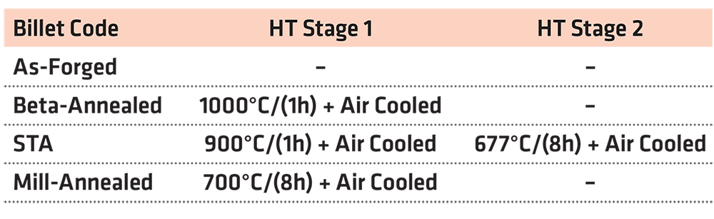
The chemical composition of Ti-6246 can be found in Table 1. The materials, provided by TIMET UK Ltd, were in billet form of outside diameter 200 mm and length 210 mm. Each billet was primary forged under the same processing conditions; however, each billet had a different microstructure, owing to different annealing heat treatments: beta-annealed, mill-annealed, and STA (solution treated and aged). One billet was also machined in the as-forged (or non-heat treated) condition. A summary of the annealing treatments applied to the billets is shown in Table 2.
2.1 Microstructural analysis
Microstructure analysis was carried out to determine the differences in the three heat-treated and as-forged conditions (Figure 1) in order to correlate with machining and force feedback response.
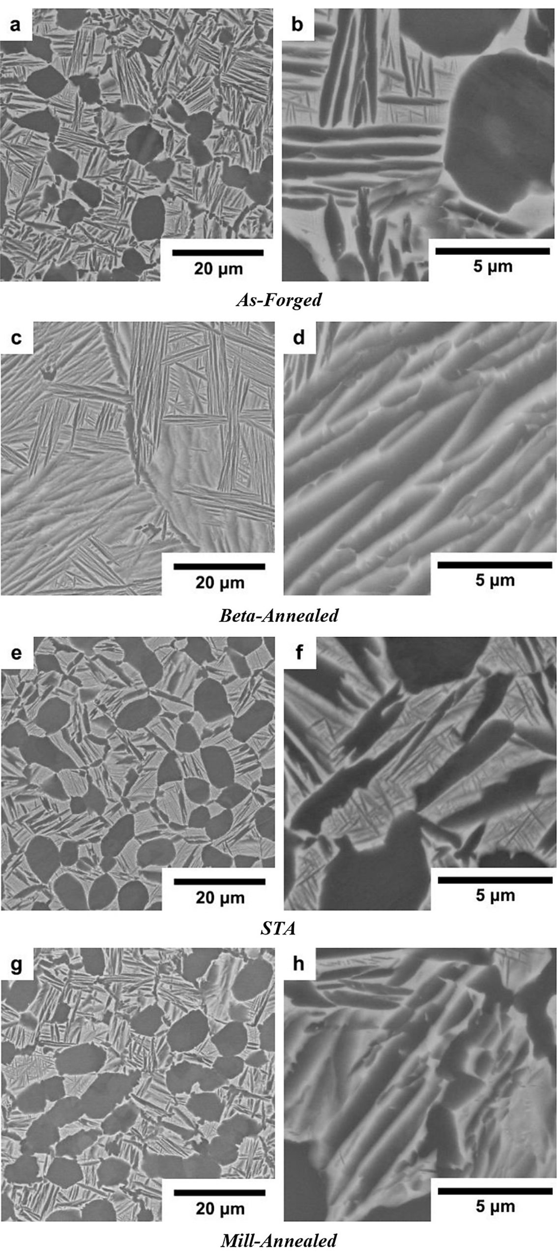
The most distinguishable microstructure out of the four conditions is the billet produced after an annealing heat treatment in the beta phase field (Figure 1c and d), which is characterized by large prior beta grains (∼500 μm diameter) with an alpha lath colony structure developed within the grains. The other three billet conditions (as-forged, mill-annealed, and STA) have very similar alpha/beta morphologies: The microstructures constitute approximately 30 vol % of equiaxed primary alpha (of size ∼5–10 μm) and transformed beta grains. The key, yet subtle, distinction between these three billets is the size and morphology of the secondary alpha laths. The duplex annealed condition (Figure 1e and f) has a slightly thinner lath structure (∼0.75 μm) compared to the mill-annealed condition (∼1.00 μm). The as-forged condition has the coarsest alpha lath structure (Figure 1a, 1b).
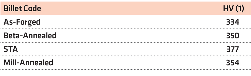
Average macrohardness (Table 3) (HV1) analysis performed in the four billet conditions in the longitudinal direction, shows that the duplex annealed condition has the highest hardness, followed by a similar hardness between the mill-annealed and the beta-annealed billets, with the as-forged condition having the lowest hardness value.
3 Methodology
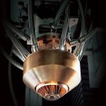
The machining process selected for the machining trials was a face turning operation. This was selected because of the relatively large surface area of the cross section of the billets with respect to their length. The machine used in the investigation was a WFL M100 MillTurn CNC machining center and the dynamometer installed to measure the cutting forces was a Kistler 9129AA (Figure 2).
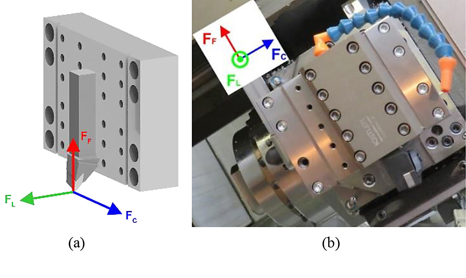
The acquisition rate used to gather information was 20 kHz, spread through eight different channels. Three different forces were measured, as labeled in Figure 2a: FC, which represents the cutting force, FF, which is parallel to the feed direction, and FL in line with the longitudinal axis of the workpiece.
The tools used in these trials were Sandvik Coromant CNMG 12 04 08-MM H13A inserts combined with a T-Max P DCLNL 2020K-12 shank tool. These inserts are uncoated carbide H13A types with a nose radius of 0.8 mm.
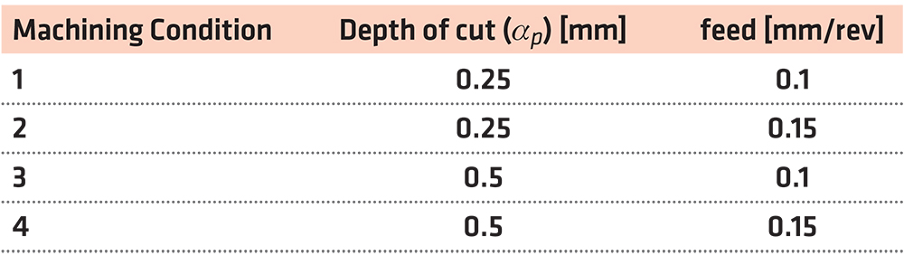
The face turning tests were performed at two different depths of cut (ap) and feed rates, but at a constant rotational speed of 62 RPM, see Table 4. The machining parameters were selected in order to simulate machining finish passes, performed when machining critical Ti-6246 aerospace components in industry.
In order to understand the local fluctuations of the three measured cutting forces (in the X-, Y- and Z-axes), the face-turning operation tool path has been mathematically parametrized to spatially synchronize the high-resolution forces measured with the exact tool location at any given time. During a face turning operation, performed at a constant RPM, the tool travels toward the center of the cross-section at a constant rate following a standard Archimedean spiral. For this type of machining operation, this is parametrized as follows:
 Where r is the instant radius, R0 is the initial radius, feed the speed at which the tool approaches the center, and time in seconds. A similar approach can be applied to the angular position, as the RPM is kept constant throughout the test.
This provides the opportunity to create representative 1:1 diagrams highlighting the local variations of cutting forces through color coding. The resultant diagrams are termed by the authors as microstructure fingerprint plots. This technique has previously been demonstrated by Suárez Fernández et al. [17] and applied to characterize the microstructural heterogeneity and perform grain size analysis and measurement in beta processed Ti-17 (Ti–5Al–2Sn–4Mo–2Zr–4Cr) alloy owing to upstream primary forging.
4 Results
The first analysis performed was the study of the force fluctuation in the four billet microstructures with respect to the average measured force. Due to the high resolution of the dynamometer and the fact that the system geometry and vibrations were consistent during the face turning of all billets, the force fluctuations could be related directly to the local microstructure.
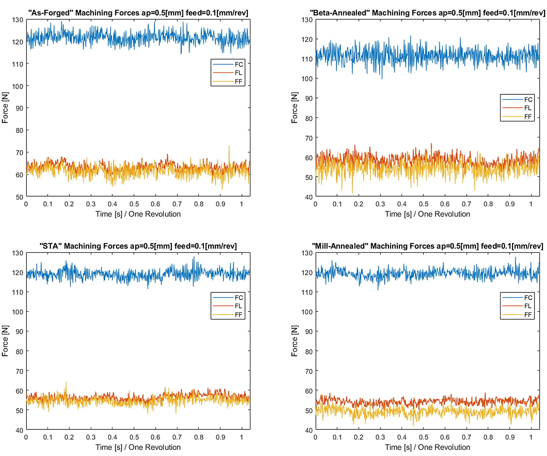
Figure 3 shows the evolution of the three machining forces (FC, FF, and FL) measured by the dynamometer during a complete rotation of the billet: The forces are plotted for each of the four heat-treatment conditions. Moreover, the cutting performance was measured to be constant during the test, regardless of the cutting speed. This is attributed to the conservative parameters selected for this finishing operation.
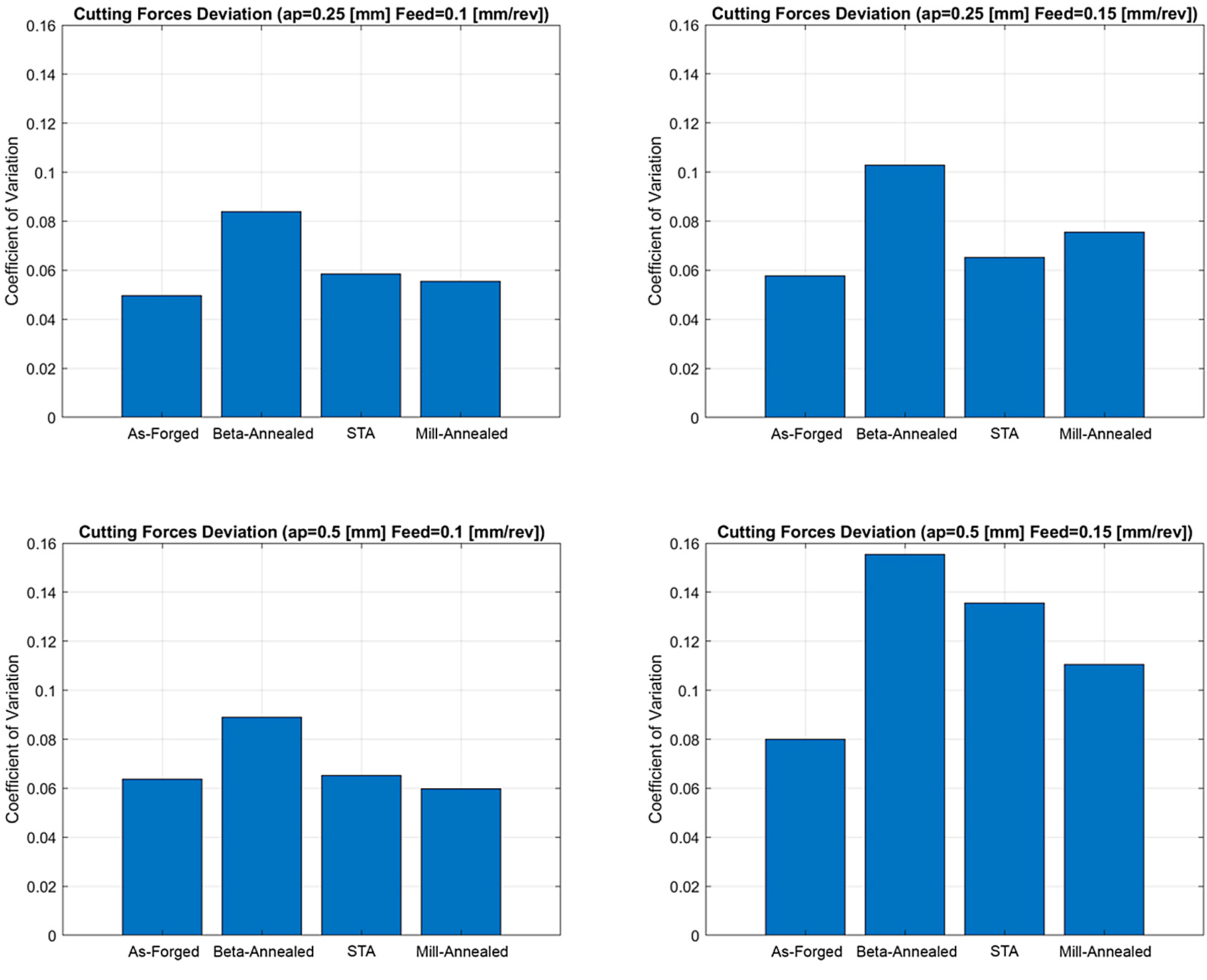
The results in Figure 4 show the coefficient of variation for the cutting force fluctuation as a function of the machining parameters and microstructure. This coefficient of variation is calculated by dividing the standard deviation by the average force during the test: This provides a value that gives information about the amplitude of those fluctuations and a common frame for comparing different tests, normalizing the results. The higher the value, the larger the fluctuations of the recorded forces with respect to the average value measured.
The data collected showed a clear trend and divided the billets into two different groups: (i) the billet heat treated above the beta transus (i. e., beta-annealed condition) and (ii) the as-forged and billets heat treated below the beta transus (i.e., mill-annealed and STA conditions). Figure 4 shows the beta-annealed billet to have the highest variation in cutting forces with respect to the average force value per test.
In contrast, the three billet conditions that have a similar bimodal microstructure of equiaxed primary alpha and transformed beta matrix display a similar force feedback trend. The greatest force fluctuation is observed in the STA condition, followed by the mill-annealed condition; the as-forged billet exhibited the most consistent force fluctuation during the face-turning operation (Figure 4). However, the cutting force fluctuations in the bimodal microstructures are not as prominent as in the case of the beta-annealed billet.
In terms of the effect of the machining parameters (Figure 5), doubling the depth of the cut (ap) did not influence the value of the coefficient of variation, which quantifies force fluctuation, as very similar results were observed between a depth of cut of 0.25 and 0.5 mm. However, increasing the feed per revolution by 50 percent showed a more distinct increase in the force fluctuation value across all four billet conditions.
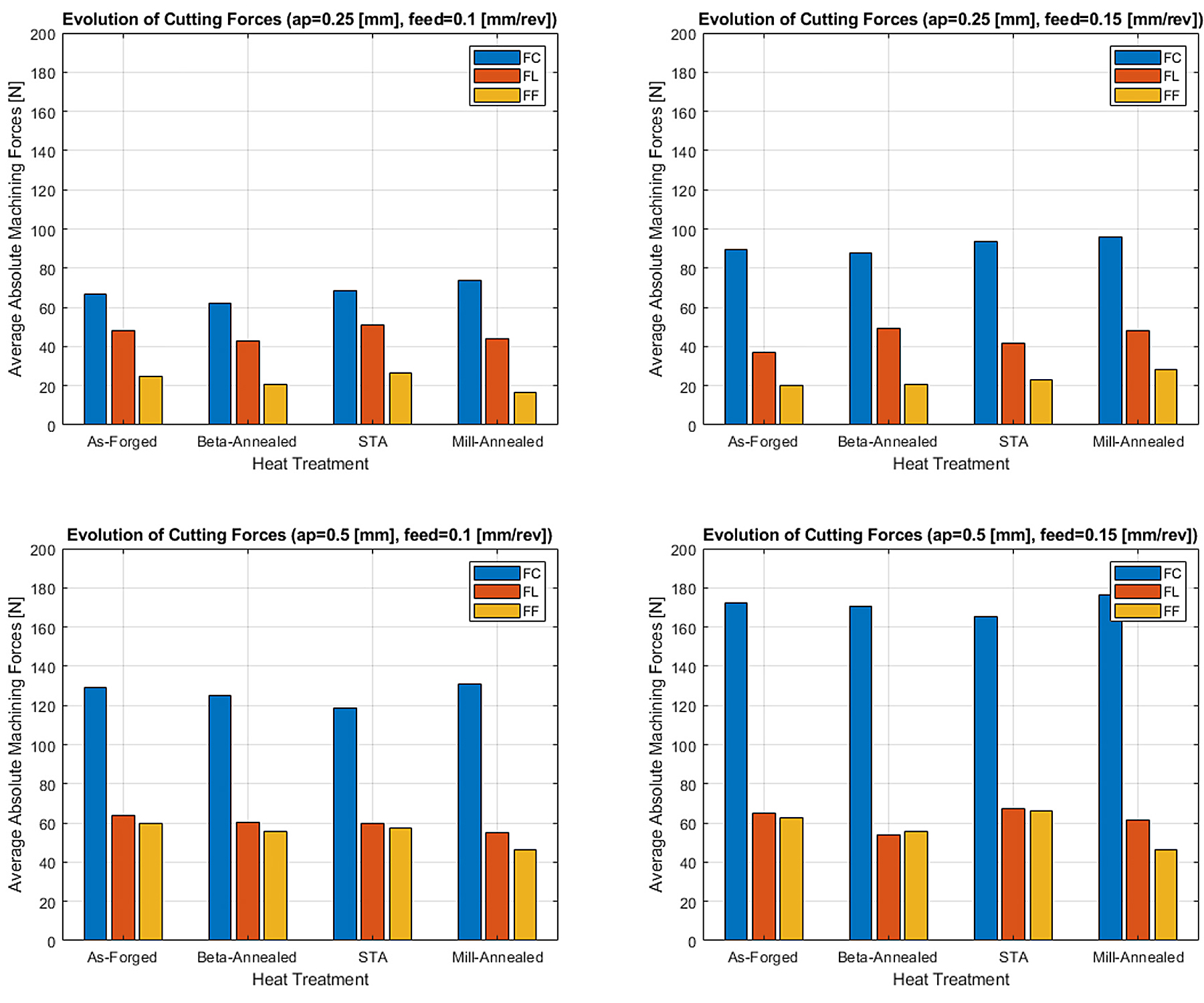
Regarding the evolution of the three elemental forces measured, similar results have been collected from all machining conditions with similar force evolution trends when increasing the feed and depth of cut. However, when performing such shallow finishing cuts, small force variations can represent large percentage increments.
Under the machining parameters selected, the general trend shows the magnitude of the cutting force (FC) dominates compared to the other longitudinal force (FL) and feed force (FF), whereby FC is more sensitive to the increase in depth of cut than the increase in feed rate. When comparing all heat treatments, the mill-annealed condition has the highest FC average value.
The FL variations are mainly affected by the depth of cut, showing almost no variation when increasing the feed per revolution by 50 percent. However, the feed force (FF) is not only affected by the feed rate: FF increases three-fold when increasing the depth of cut by 50 percent, reaching parity with the longitudinal force when the depth of cut is set to 0.5 mm. Figure 6a shows a billet face microstructure fingerprint plot reconstructed from the force feedback from a face turning operation performed in the Ti-6246 as-forged billet. In these reconstructed images, it is possible to distinguish features that can be related to the upstream forging process.
From the reconstructed force plots shown in Figure 6a, the first distinct feature is the extruded core denoted by the high force response at the central region of the billet. This is developed during the primary forging when the large vacuum arc re-melted (VAR) ingot is broken down into a smaller diameter billet form with a refined microstructure. This process is described by Wilson et al. [19] showing the strain evolution and texture development during primary forging for such billets. The cutting force also varies along the outside region of the billet cross section, where the higher cutting forces reveal four poles where the plastic strain is concentrated during the primary forging operation. Finally, the low strain axis is highlighted with a vertical black line. This low strain axis is represented by the outer diameter regions where lower cutting forces are registered compared to the central region. Such machining heterogeneities can be attributed to the strain path history that the material experience during forging.
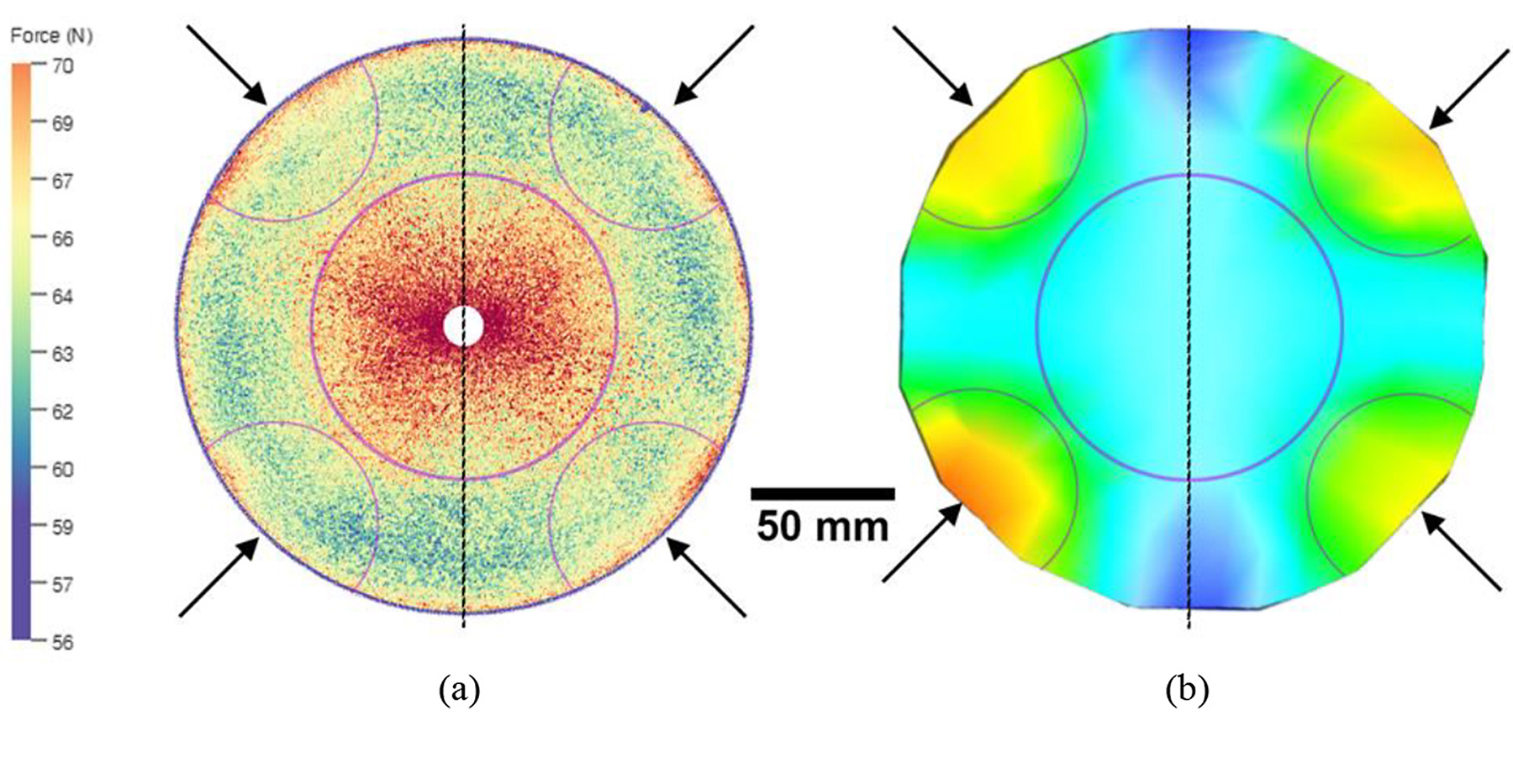
The model shown in Figure 6b shows a DEFORM simulation provided by TIMET UK Ltd. where a similar open-die, forging operation has been simulated. The color in this case represents the forging strain pattern and the different strain levels induced into the cross section of the billet during primary forging. The high and low strain regions generated in the DEFORM simulation correlate very well with the cutting force data in the corresponding microstructure fingerprint plot.
These microstructure fingerprint plots have been obtained for the four analyzed Ti-6246 billets. Figure 7 shows the reconstruction of these diagrams using the longitudinal force (FL) for the billets.
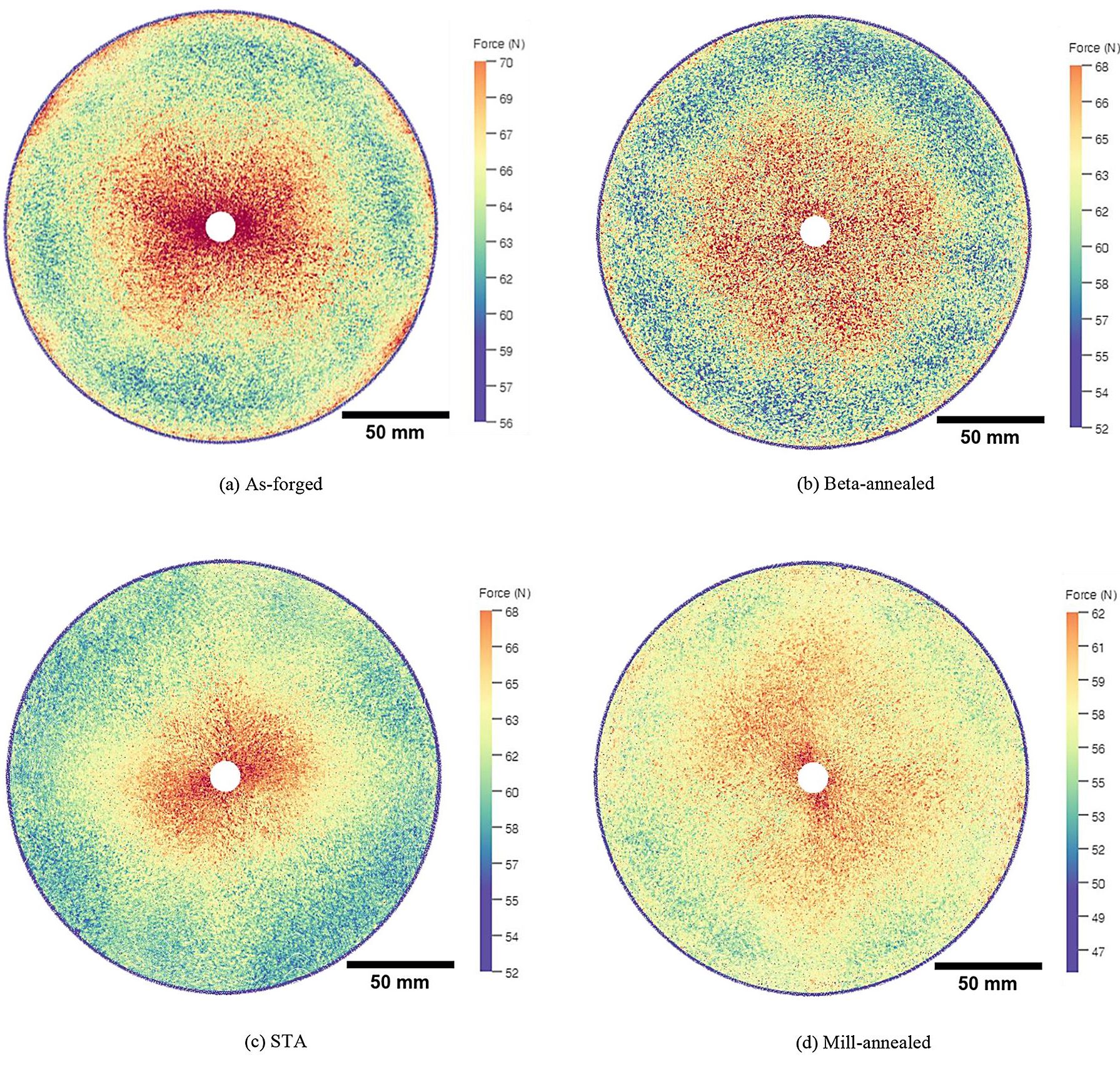
Microstructure fingerprint plots of the four billets (Figure 7) have been generated through the synchronization of the longitudinal force (FL) with the tool path. The points plotted represent the average of every 30th point measured at 20 kHz, representing an equivalent 667 points per second. The resolution at 20 kHz and 62 RPM at the outer radius (lowest resolution in the circumferential axis during the test) is 30.8 points/mm (32.46 µm), increasing linearly toward the center. The resolution in the radial axis is given by the feed per revolution, which in this case is 100 µm (0.1 mm/rev).
The color code and scale show higher and lower forces in red and blue, respectively. The range for the color scale used for the microstructure fingerprint plots in Figure 7 was calculated for each case as ±8 N from the average cutting force during the test. For comparison purposes, these plots were reconstructed from the force signal gathered from the tests with a depth of cut of 0.5 mm and a feed per revolution of 0.1 mm/rev.
Although the historical effects of the heterogeneous deformation from the primary forging stage is evident in all the fingerprint plots, a more prominent extruded core is observed in the as-forged billet. If we consider the as-forged billet as the baseline condition, the subsequent annealing treatments reduce the effect of the harder-to-cut extruded core region, especially in the STA and mill-annealed conditions, with a less-than-prominent reduction in the beta-annealed condition.
Figure 8 depicts a detailed image of the beta-annealed billet microstructure fingerprint plot and highlights the machining structural units, regions that present similar cutting performance. Note there is a significant difference in cutting performance (and hence color/hue) between the central and peripheral regions of the billet.

The higher variability in the cutting forces, especially in the beta-annealed billet, is also observed in the local analysis of the cutting forces shown in Figures 7b and 8. Regions with very dissimilar cutting performance are shown in these plots. This supports the results where the beta processed cutting forces show a higher coefficient of variation and hence a higher standard deviation.
Although these force fluctuations are not as prone as in the supertransus (beta-annealed) heat treatment, for the three subtransus condi tions (i.e mill-annealed, STA, and as-forged), there is a strong relationship between the modulus of the measured resultant force and the secondary alpha lath thickness (plotted in Figure 9). An inverse linear relationship between the secondary alpha lath size and microhardness is shown, which is consistent with the previous literature [20–22].
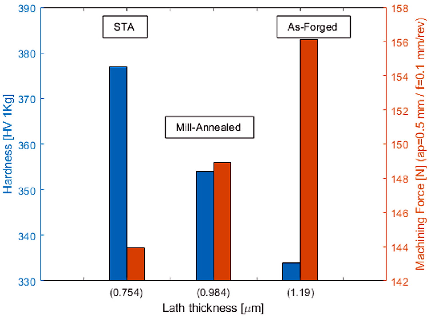
Interestingly, as Figure 9 illustrates, a linear relationship exists between the secondary alpha lath thickness and the resultant machining force modulus; thicker secondary alpha lath microstructures resulted in a greater cutting force.
5 Discussion
The largest cutting force variability shown in Figure 4 among the Ti- 6246 billet conditions analyzed was observed in the beta-annealed condition. This can be linked to the distinctive microstructure, which consists of large prior beta grains and a secondary alpha lath morphology. The anisotropic alpha (hcp) laths within the prior beta grains exist as both “hard” and “soft” crystallographic orientations with respect to a particular cutting direction. For example, the C-axis orientation of “hard” secondary alpha laths is near-parallel to the loading direction; the C-axis orientation of “soft” secondary alpha laths will be perpendicular [23]. [24] showed the alpha texture developed in Tim et al. 550 was influenced by the variant selection occurring in the beta to alpha transformation. Zarkades et al. [25] previously described the variation of the Young’s modulus with respect to the C-axis orientation in alpha titanium. These orientation effects, combined with Stroh’s proposed mechanism [26] of plastic flow and strain accommodation for crack formation can be directly applied to a machining scenario, as a crack forms in the primary shear zone, separating the chip from the new surface.
As evidenced in this study, microstructure and alpha lath size and orientation determines the tool response during face-turning of the Ti- 6246 workpiece. As Figure 8 demonstrates, for the beta-annealed condition, the force response across a large grain is consistent, and thus be considered as a “machining unit.” The misorientation between neighboring large grains or machining units is captured through the variability in force response. Such sensitivity to orientation effects was observed and replicated, regardless of the depth of cut and feed machining parameters applied. These relatively large variabilities in the cutting force (in some cases up to ∼Δ60 N) for beta-annealed titanium alloys are clearly linked to the anecdotal observations by experienced machinists in the industry that such billet conditions are more difficult to machine compared to subtransus and fine-grained conditions. Moreover, Cedergren et al. [27] also observed distinct changes in vibration and chip formation between fine and coarse grained Ti-64 material, respectively. For example, coarse grained Ti-64 produced greater machine tool vibrations, less stable machining, and produced a more serrated chip form. The less machinable performance of metastable beta-titanium alloys compared to alpha + beta alloys, was also reported by Arrazola et al. [28]. In addition, the effects of different heat treatment conditions in metastable beta alloys and alpha + beta alloys on machinability have also been observed by Khannaa et al. [29] and Khannaa and Sangwan [30]. All these researchers conclude that alpha + beta titanium alloys processed under supertransus conditions are substantially more difficult to machine than material processed under subtransus conditions.
Large fluctuations in forces during machining will also be detrimental from a tool life standpoint, owing to the dynamic variation in tool-titanium workpiece interaction. For example, this is reported in Ti- 5553 by Arrazola et al. [31], where tool wear was linked to the adiabatic shear band formation in the generated chips, creating excessive thermal and mechanical fatigue on the insert.
However, in the case of the bimodal structures, the cutting force fluctuations were not as prominent, as in the case of the beta-annealed billet. This is due to the finer structural units developed during the subtransus heat-treatment conditions. Processing below the beta transus temperature (α+β region) has little effect on the primary alpha size and morphology, which in these three cases are very similar. Although there are differences in the lath size thicknesses of the secondary alpha developed, such differences are not large enough to be resolved by the tool-dynamometer system used in this study. This lack of resolution can be attributed to the machining parameters selected — i.e. very shallow cuts combined with a relatively blunt tool.
Figures 6 and 7 show the local machining force fluctuations (FL) in the cross section of the machined billets, showing the relationship between these variations and the forging process. When comparing the results in Figure 7 and considering the as-forged condition as the baseline, it is clear the annealing heat treatments reduce the effects of the local machining heterogeneities derived by the plastic strain induced during the billet forging, which are revealed as four poles from the machining force response, Figure 6. This is more prominent in the subtransus heat treatments, i.e., mill-annealed and STA. This reduction in machinability heterogeneities can be linked to the duration and temperature of the heat treatment, as reported by Lütjering and Williams [32], where the differences in cutting forces between the outer region and the center of the cross-section are less prominent than in the other billet conditions.
However, it is important to highlight that, even though the forging heterogeneities can be mitigated by the heat treatment, Figure 8 shows the machining structural units presented after the supertransus heat treatment in the beta-annealed billet, which induces a different level of local machining heterogeneities not seen in the subtransus treatments. These microstructural features can affect the tool life negatively, creating a variable pressure front on the cutting edge, which links with the larger variability in machining forces observed in the beta-annealed billet.
Figure 9 presents an inverse linear relationship between the secondary alpha lath size and microhardness, which is consistent with previous research [20] where the hardness/yield strength increased with decreasing alpha lath size [21] because of the reduction in the effective slip length: finer secondary alpha microstructures, i.e., STA billet, have a higher hardness value compared to the mill-annealed and as-forged billets, which have thicker secondary alpha laths. This is also supported by crystal plasticity simulations reported by Hemery et al. [22] for Ti-6242.
Initially, the trends shown in Figure 9 can be considered counter-intuitive with harder material resulting in lower cutting forces. However, it is important to highlight that hardness testing and face-turning induce different material responses that can result in different material behavior. In the case of the results shown in Figure 9 where alpha lath thickness and hardness are compared, a similar trend was reported by Sui et al. (2007). This trend has also been demonstrated between the UTS and the average alpha lath thickness by Tiley [33] in alloy Ti-64.
During machining of subtransus microstructures, the force response is sensitive to the size and morphology of the secondary alpha laths. Therefore, the mechanism of how deformation slip is transferred between alpha laths prior to crack formation (and chip forming) ahead of the primary shear zone clearly has an effect on the resultant forces. The results in Figure 9 show that thinner alpha laths lead to a lower cutting force, which suggests that they are easier to plastically deform (prior to shear band formation) at the high strain rates, possibly due to the reduction of the effective slip length.
6 Conclusions
In this study, it has been demonstrated for the first time that different Ti-6246 billet microstructures — as-forged, mill-annealed, beta-annealed, and STA conditions — can be characterized through microstructure fingerprint plots directly from the cutting forces in the three spatial axes. There is a clear distinction between the beta-annealed condition and the other “subtransus” processed conditions, with a much greater cutting force variation (30 to 40 percent higher) in the former. The strain heterogeneity deriving from the primary forging process is also evident in the as-forged condition and to a lesser extent in the post forging heat-treatment conditions (i.e., mill-annealed, beta-annealed and STA).
The resolution of the force feedback technique is sufficient to capture local variations in grain orientation. Furthermore, the technique is sensitive enough to detect changes in the secondary alpha lath thickness in the transformed beta for the “subtransus” processed conditions; as the alpha lath thickness increases the cutting force increases.
With further development, this force feedback approach can be used as an in-process machining NDE technique to determine forging heterogeneities induced by the primary and secondary forging processes and subsequent heat-treatment stages, as described by Suárez Fernández et al. [17].
The authors envision that, in the future, such microstructure finger- print plots presented in this study could be electronically tagged to the material route card at each manufacturing stage, providing the basis of an in-process machining NDE approach. This will provide the material producer with a rapid digital twin of the microstructure at key processing stages — from ingot through to final component. Such an in-process machining NDE approach will also provide additional quality assurance of material such as Ti-6246 in a range of heat-treatment conditions.
Data availability
The raw/processed data required to reproduce these findings cannot be shared at this time as the data also forms part of an ongoing study.
Credit authorship contribution statement
D. Suárez Fernández: investigation, visualization, methodology, writing – review and editing, code, experiments. B.P. Wynne: methodology, writing – review and editing. P. Crawforth: methodology, writing – review and editing. M. Jackson: investigation, writing –review and editing.
Declaration of competing interest
The authors declare that they have no known competing financial interests or personal relationships that could have appeared to influence the work reported in this paper.
Acknowledgements
The authors gratefully acknowledge the support of Kate Fox from Rolls-Royce. This research was supported by the EPSRC grant EP/ L016273 Centre for Doctoral Training in Advanced Metallic Systems and EPSRC grant EP/S013377/1.
References
- J. Halford, President, Arconic Engineered Structures, in: Driving Growth through Innovation: Commercial and Military Titanium Demand, 2018. Titanium Asia 2018.
- M.S. Hussain, C. Siemers, J. Rösler, Development of a free- machining (α+β) titanium alloy based on Ti-6Al-2Sn-4Zr-6Mo, Mater. Manuf. Process. 28 (issue 5) (2013) 545–549.
- S. Cedergren, G. Petti, G. Sjoberg, On the influence of work material microstructure on chip formation, cutting forces and acoustic emission when machining Ti-6Al-4V, Procedia CIRP 12 (2013) 55–60.
- S.W. Williams, F. Martina, A.C. Addison, J. Ding, G. Pardal, P. Colegrove, Wire arc additive manufacturing, Mater. Sci. Technol. 32 (7) (2016) 641–647.
- S. Seong, O. Youmossi, B.W. Goldsmith, Titanium: Industrial Base, Price Trends, and Technology Initiatives, RAND Corporation, Santa Monica, 2009. https://www.google.com/search?q=Goldsmith+W.+Titanium%3A+Industrial+Base%2C+Price+Trends%2C+and+Technology+Initiatives&oq=Goldsmith+W.+Titanium%3A+Industrial+Base%2C+Price+Trends%2C+and+Technology+Initiatives&aqs=chrome..69i57.735j0j7&sourceid=chrome&ie=UTF-8.
- O. Hatt, Z. Lomas, M. Thomas, M. Jackson, The effect of titanium alloy chemistry on machining induced tool crater wear characteristics, Wear 408–409 (2018) 200–207, 2018.
- M. Armendia, P. Osborne, A. Garay, J. Belloso, S. Turner, P.J. Arrazola, Influence of heat treatment on the machinability of titanium alloys, Mater. Manuf. Process. 27 (4) (2012) 457–461.
- B. Denkena, T. Grove, The Effect of Microstructure on the Machinability of Ti-6Al-4V. Proceedings of the 13th World Conference on Titanium, 2016, pp. 905–910.
- S.V. Telrandhe, A.K. Saxena, S. Mishra, Effect of microstructure and cutting speed on machining behavior of Ti6Al4V alloy, J. Mech. Sci. Technol. 31 (2017) 2177–2184.
- Z. Pan, Y. Feng, S.Y. Liang, Material microstructure affected machining: a review,” Manuf. Rev. 4 (2017) https://doi.org/10.1051/mfreview/2017004 article 5.
- A. Eduardo Diniz, A. Rocha Machado, J. Geilser Correa, Tool wear mechanisms in the machining of steels and stainless steels,” Int. J. Adv. Manuf. Technol. 87 (2016) 3157–3168.
- A. Graves, S. Norgren, P. Crawforth, M. Jackson, A Novel Method for Investigating Drilling Machinability of Titanium Alloys Using Velocity Force Maps 2020 AIME-D- 20-00059, 2021. Unpublished work.
- G. Welsch, R. Boyer, E.W. Collings, Materials Properties Handbook: Titanium Alloys, ASM International, 1993, ISBN 9780871704818.
- S.D. Henry, K.S. Dragolich, N.D. DiMatteo, Fatigue Data Book: Light Structural Alloys, ASM international, 1994. ISBN 9780871705075.
- I. Inagaki, T. Takechi, Y.S. Ariyasu, Application and features of titanium for the aerospace industry, Nippon Steel and Sumitomo Metal Technical Report No. 106. Technical Review UDC 669 295 (629) (2014), 735 . 3.
- SAE, Aerospace Material Specification (AMS) Titanium Alloy Bars, Wire, and Forgings 6.0Al – 2.0Sn – 4.0Zr – 6.0Mo Solution and Precipitation Heat Treated, SAE AMS 4981E.
- D. Suárez Fernández, M. Jackson, P. Crawforth, K. Fox, B.P. Wynne, Using machining force feedback to quantify grain size in beta titanium, Materialia 13 (2020), 100856.
- D. Suárez Fernández, B.P. Wynne, P. Crawforth, K. Fox, M. Jackson, The effect of forging texture and machining parameters on the fatigue performance of titanium alloy disc components, Int. J. Fatig. 142 (2021), 105949.
- A. Wilson, V. Venkatesh, R. Pather, J.W. Brooks, S.P. Fox, The prediction of microstructural development during TIMETAL 6-4 billet manufacture, in: Proceedings for world conference on titanium, 2003, pp. 321–328. Ti-2003, (2003), https://www.tib.eu/en/search/id/BLCP%3ACN053606841/The-Predict ion-of-Microstructural-Development-during/.
- Y. Sui, B. Li, A. Lui, J. Gijo, H. Fu, Microstructures and hardness of Ti-6Al-4V alloy staging castings under centrifugal field, T. NONFERR METAL SOC 18 (Issue 2) (2008) 291–296. https://www.sciencedirect.com/science/article/abs/pii/S1003632608600515.
- I. Sen, S. Tamirisakandala, D.B. Miracle, U. Ramamurty, Microstructural effects on the mechanical behaviour of B-modified Ti-6Al-4V alloys, Acta Mater. 55 (15) (2007) 4983–4993.
- S. Hemery, P. Villechaise, D. Banerjee, Microplasticity at room temperature in α/β titanium alloys, Metall. Mater. Trans. 51 (2020) 4931–4969, https://doi.org/ 10.1007/s11661-020-05945-4.
- D. Rugg, M. Dixon, F.P.E. Dunne, Effective structural unit size in titanium alloys, J. Strain Anal. Eng. Des. 42 (4) (2007) 269–279.
- E. Lee, R. Banerjee, S. Kar, D. Bhattacharyya, H.L. Fraser, Selection of α variants during microstructural evolution in α/β titanium alloys, Phil. Mag. 87 (24) (2007) 3615–3627. https://www.tandfonline.com/doi/abs/10.1080/14786430701373672.
- A. Zarkades, F. Larson, Elasticity of titanium sheet alloys, the science, technology and application of titanium, 1970, pp. 933–941. https://www.sciencedirect.com/s cience/article/pii/B9780080065649501044.
- A.N. Stroh, The formation of cracks as a result of plastic flow, Proc. R. Soc. Lond. A: Math 223 (1954) 404–414. https://royalsocietypublishing.org/doi/10.1098/rspa. 1954.0124.
- S. Cedergren, C. Frangoudis, A. Archenti, R. Pederson, G. Sjolberg, Influence of work material microstructure on vibrations when machining cast Ti-6Al-4V, Int. J. Adv. Manuf. Technol. 84 (2015) 2277–2291.
- P.J. Arrazola, L.M. Iriarte, A. Garay, S. Marya, J. Vigneau, Felix Le Maître, Machinability of Near Beta Titanium Alloys Employed in Aeronautics, Proceedings of the 11th World Conference on Titanium (JIMIC 5), The Japan Institute of Metals, 2007.
- N. Khannaa, A. Garay, L.M. Iriarte, D. Soler, K.S. Sangwan, P.J. Arrazola, Effect of heat treatment conditions on the machinability of Ti64 and Ti54M alloys, Procedia CIRP 1 (2012) 477–482.
- N. Khannaa, K.S. Sangwan, Machinability study of α/β and β titanium alloys in different heat treatment conditions, Proc IMechE Part B: J Engineering Manufacture 227 (3) (2013) 357–361. https://www.researchgate.net/publication/236116058_Machinability_study_of_and_titanium_alloys_in_different_heat_treatment_conditions.
- P.J. Arrazola, A. Garay, L.M. Iriarte, M. Armendia, S. Marya, F. Le Maître, Machinability of titanium alloys (Ti6Al4V and Ti555.3), J. Mater. Process. Technol. 209 (2009) 2223–2230. Elsevier.
- G. Lütjering, J.C. Williams, Titanium, Springer Science & Business Media, 2007, ISBN 978-3-540-71397-5.
- J.S. Tiley, Modelling of Microstructure Property Relationships in Ti-6Al-4V, PhD Thesis, Ohio State University, 2002. TIMET product datasheet Timetal-6246, http s://www.proquest.com/docview/305303926.
About the authors
D. Suárez Fernández is with the Department of Materials Science and Engineering, The University of Sheffield, Sir Robert Hadfield Building, Mappin St, Sheffield, S1 3JD, U.K. and the Advanced Manufacturing Research Centre, Advanced Manufacturing Park, Catcliffe, Rotherham, S60 5TZ, U.K. B.P. Wynne is with the Department of Mechanical and Aerospace Engineering, University of Strathclyde, Glasgow, G1 1XJ, U.K. P. Crawforth is with the Advanced Manufacturing Research Centre. M. Jackson is with the Department of Materials Science and Engineering, The University of Sheffield.
© 2021 The Authors. (https://doi.org/10.1016/j.msea.2021.141074) Published by Elsevier B.V.
This is an open access article under the CC BY license (http://creativecommons.org/licenses/by/4.0/). It has been edited to conform to the style of Thermal Processing magazine.


 general practice for CQI-9 and AMS2750E")


