


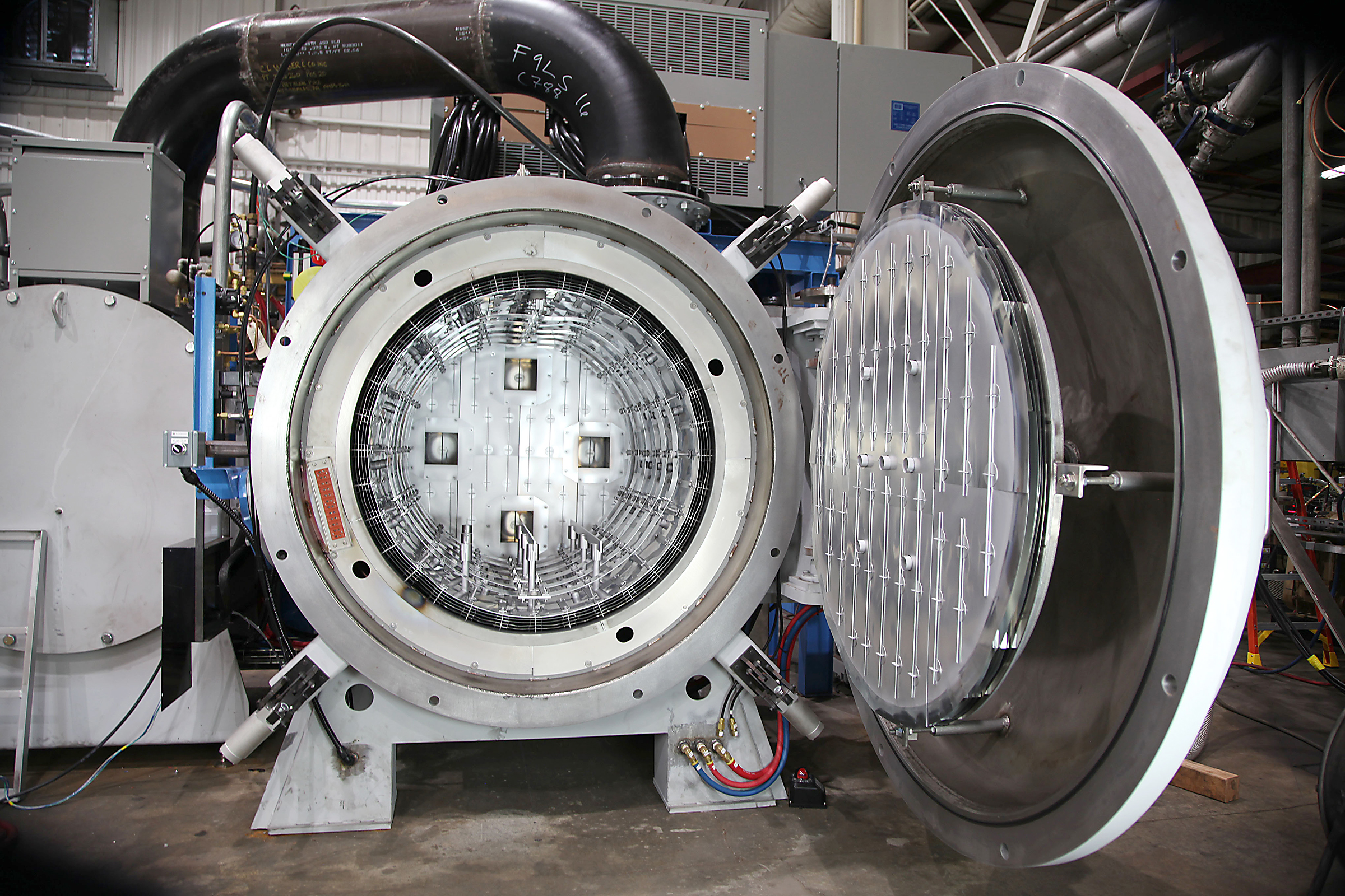
Over the years, there have been many variations of hot zone insulation designs for vacuum furnace hot zones and can include the following configurations and materials. This article will summarize these designs with performance results in vacuum and power efficiency:
• a: Graphite foil facing backed by 2”-3” Kaowool insulation.
• b: Graphite foil facing backed by 2” PAN graphite felt.
• c: Graphite foil facing backed by 2” Rayon graphite felt.
• d: Standard Graphite board (2”) with foil facing.
• e: New GMI Graphite board (2”) with foil facing [1].
• f: All Metal (3 molybdenum, 2 stainless steel shields).
• g: All Metal (5 molybdenum shields).
How a vacuum furnace hot zone is insulated and selected is based on several factors including:
• 1: Desired ultimate vacuum level.
• 2: Maximum processing temperature.
• 3: Overall thermal efficiency and power losses.
• 4: Overall cycle time.
• 5: Minimal part surface contamination.
Analyzing the above factors individually, the following can be summarized:
1 Desired ultimate vacuum level
Many processes only require what might be called “soft vacuum” with an operating level in the mm Hg range or 10-3 to 10-4 Torr range. This can normally be achieved with any insulated hot-zone design. Hot-zone materials for (e) would easily meet this requirement.
Other processes require a super-clean environment with vacuum levels in the 10-5 Torr range or higher. These processes could be performed in the (b) through (e) hot zones.
Processes requiring a vacuum of 10-6 Torr or better normally require an all-metal hot zone design (f) and (g) to achieve the required vacuum levels and produce super-clean work.
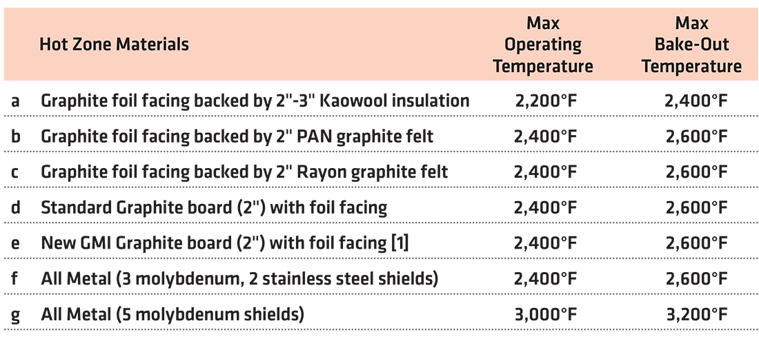
2 Maximum processing temperature
Table 1 illustrates the relative maximum operating temperatures that are typically available with each hot-zone configuration.
Although some of the hot zones are often heated above the normal operating temperatures, these are the recommended normal processing temperatures.
3 Overall thermal efficiency and power losses
The efficiency of a particular hot zone is determined by the power losses being radiated from the outer support ring to the inner cold wall of the vacuum chamber. The outer support ring temperature varies based on the insulating materials. The ring temperature is most critical in that it is raised to the fourth power when calculating power losses. The relative outer ring holding temperatures for the different configurations are shown in Table 2.
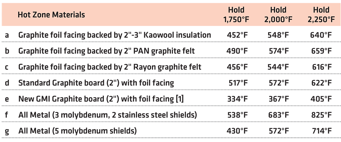
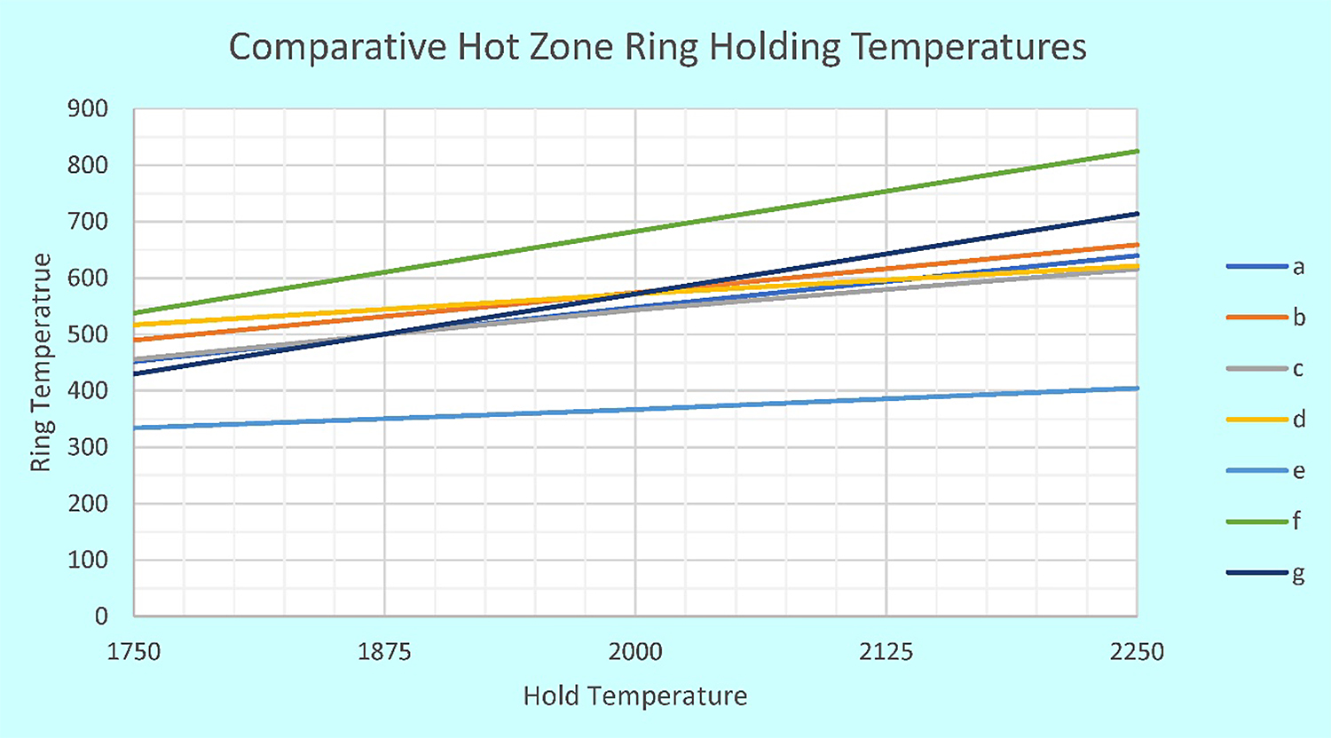
Figure 1 illustrates several things. These include:
• a: Rayon graphite felt is more efficient than PAN graphite felt.
• b: The GMI board material [1] is more efficient than any other insulations or shield combinations. This board material also grows more efficient as the temperature rises.
• c: The all-metal hot zones are most inefficient.
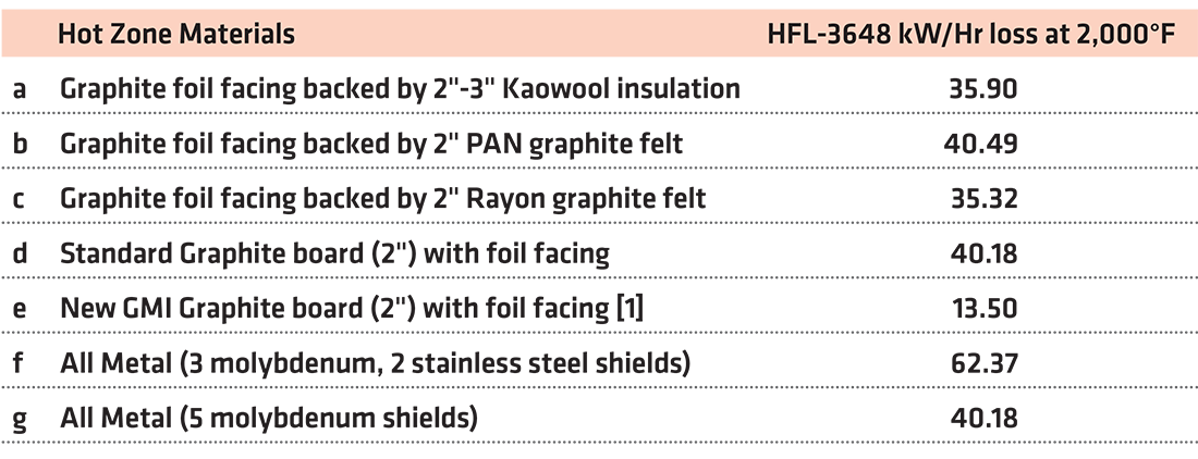
Table 3 illustrates the projected relative power losses and wall density for the HFL-3648 Furnace when holding at 2,000°F. The furnace has a working hot zone that measures 36” W x 36” H x 48” D.
With Table 3, we can conclude the following:
• a: The Rayon Felt hot zone is approximately 12.8% more efficient than the PAN hot zone.
• b: The GMI Board [1] hot zone is approximately 61.8% more efficient than the Rayon hot zone and approximately 66.7% more efficient than the PAN hot zone.
• c: The all-metal hot zone (f) is the least power efficient of all the various insulation configurations.
4 Overall Cycle Time
The overall cycle time for a furnace is based on several factors. These include:
• a: Vacuum pumping capacity.
• b: Insulation moisture absorption characteristic of the insulation, most critical when the furnace door is open too long, especially on humid days.
• c: Efficiency of insulation to overcome recurring losses when heating the workload.
• d: Workload mass and thickness of parts being processed.
• e: Gas cooling system recirculating volume capability and cooling gas used based on process requirements.
• f: Type of insulation used in the hot zone.
5 Minimal part surface contamination
When working with felt-insulated vacuum furnaces, moisture, water, and pick-up can become key sources of oxygen contamination. For comparative testing, samples of PAN and Rayon felt stacks, top insulation for the hot zone only, were prepared for testing in a lab furnace. The furnace cycle for each stack ran with a clean titanium test piece in the furnace. This was compared to an all-metal shield test package. After each run, alpha-case analysis via metallurgical evaluation determined the level of contamination from moisture pickup for both PAN and Rayon insulation compared to the clean all-metal hot zone.
The vacuum levels for each insulation package shown in the following chart, when compared to the standard all-metal hot zone, show less effective vacuum levels, indicating the presence of more residual gas. It should be noted that the humidity and dew point was considerably higher on the date of Rayon testing than the PAN test date. With this fact in evidence, the results in Figure 2 indicate the PAN insulation is much more sensitive to moisture pick-up than Rayon-based felt.

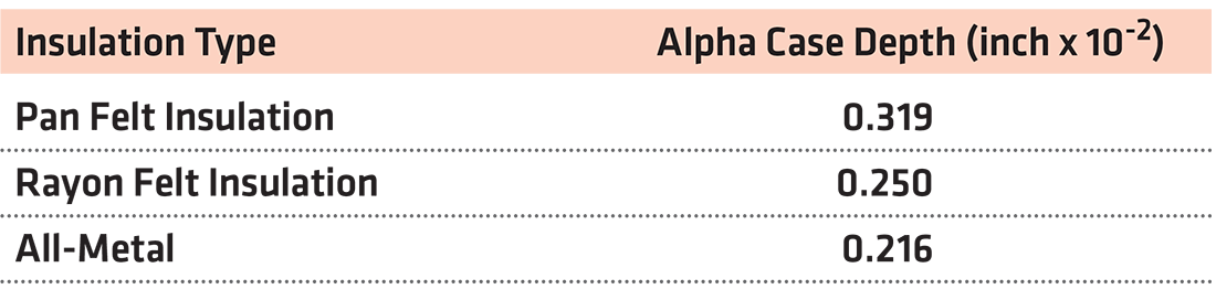
The resultant alpha case measurements also support this conclusion considering the titanium sample used in the Rayon insulation testing produced a similar alpha case result to the all-metal hot zone, even though the Rayon felt stack suffered more severe humidity that the PAN test samples. (Comments based on a limited test.)
The results in Table 4 illustrate that the all-metal hot zone is superior and required for most super-clean applications.
6 Conclusions
As is illustrated in this presentation, there are considerable factors that must be evaluated when selecting the proper hot zone design for the application and intended use.
One remaining consideration, which was not included above, is the relative cost for each different configuration. Listing each hot zone from least expensive to most expensive, we have Table 5.
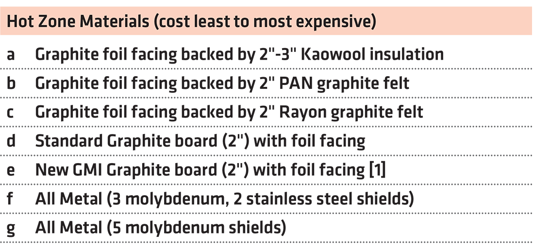
The comments in Table 5 should help future buyers in selecting the right vacuum furnace hot zone design for their specific application.
References
William R. Jones, CEO Emeritus, Solar Manufacturing Inc., wrj@solaratm.com, contributed to this article.


 general practice for CQI-9 and AMS2750E")


