


There are many critical factors that are assessed when designing a gear that will be used in demanding applications such as engines or transmissions. Design engineers typically assess gear material, availability, cost, formability, machineability, and heat-treat ability for the specific application. They also evaluate the materials’ anticipated loads and the materials’ mechanical properties, such as tensile, yield, elongation, reduction in area, thermal properties, and life cycles. A shorter summary or outline could be easily stated as component design, material selection, heat-treat method, and potential enhancements of heat-treatment processes. Many times these variables are simulated by finite element analysis (FEA).
FEA is a computerized method for predicting how the design will react to the application’s environments such as vibration, noise, thermal dynamics, and whether the components will wear out, break, or work the way it is designed. FEA analysis can save a lot of development costs. Case-hardened gears, e.g. carburizing, are used for the harshest environments where strength and wear properties are essential. Case-hardened gears exhibit a 30-percent to 50-percent increase in load-bearing capacity when compared to through hardening. It is also used where gears are subjected to high sliding and rolling contact, which leads to stresses on the active profile of the gear flank and Hertzian stresses in the gear root.
Carburizing is a high-temperature heat-treat process (898-954º C) in which a higher percentage of carbon, i.e. 0.80 percent to 1.20 percent, is added to the atmosphere on materials typically containing less than 0.27 percent carbon. The depth of carbon penetration is dependent upon time and temperature of the treatment and also can be influenced by the furnace type. After carburizing, the part is hardened by lowering to a specified hardening temperature, stabilizing, and then quenching in a suitable media, immediately followed by tempering. Please note that untempered martensite is very unstable, so the primary goal is a microstructure of primarily tempered martensite. Some of the undesirable by-products of the process may include bainite, retained austenite, carbide networking, and core ferrite.
One of the primary considerations or potential problems in developing process parameters includes material handling that does not damage, nick, or alter the gear geometry in the softened state. Other considerations include process time, carburizing temperature, hardening temperature, atmosphere, quench media, and temper to ensure optimum metallurgical properties, dimensional stability, and durability and reliability requirements for the specific application where the gear will operate.
Commercially, the heat treater needs to supply a quality product at a competitive price, while coordinating many people, facilities, and supplies with an emphasis on delivering such in a timely fashion. There are sources of variation that need to be fully defined, communicated, documented, and incorporated into the process on a consistent, repeatable, and reproducible basis.
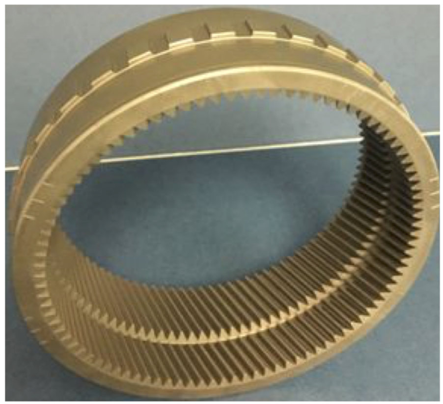
The gear chosen for this article (Figure 1) is assembled into a 6-speed, rear-wheel drive transmission with a five-year, 60,000-mile warranty. The material chosen for this application is a finished machined SAE 5130H steel. It is classified as a “carbon alloy steel” because it has 0.27-percent to 0.30-percent carbon with 0.75-percent to 1.20-percent chromium. The chromium increases hardenability and strength at high operating temperatures. The “H” designation is for increased or more consistent hardenability and is accomplished by modifying the manganese. Manganese also increases strength and toughness. The “DI” or “Ideal Critical Diameter” is a quantitative method of determining the depth of hardenability and, in the case of this application, is 76.2 mm to 88.9 mm (3.0 inches to 3.5 inches) per SAE J406, May 1998.
Part Handling / Racking
A key process control in ensuring product integrity is racking of the gear on the fixture prior to heat treat. Prior to the heat-treat process being performed, special attention needs to be placed upon heat-treat rack or fixture design (Figure 2). The fixture is typically cast from a temperature-resistant 300 series stainless steel. The size and configuration of the fixture must be conducive with the part geometry. Weight of the fixture is also critical because the fixture has to be heated and quenched along with parts. Figure 2 is a diagram of the fixture design for this application.

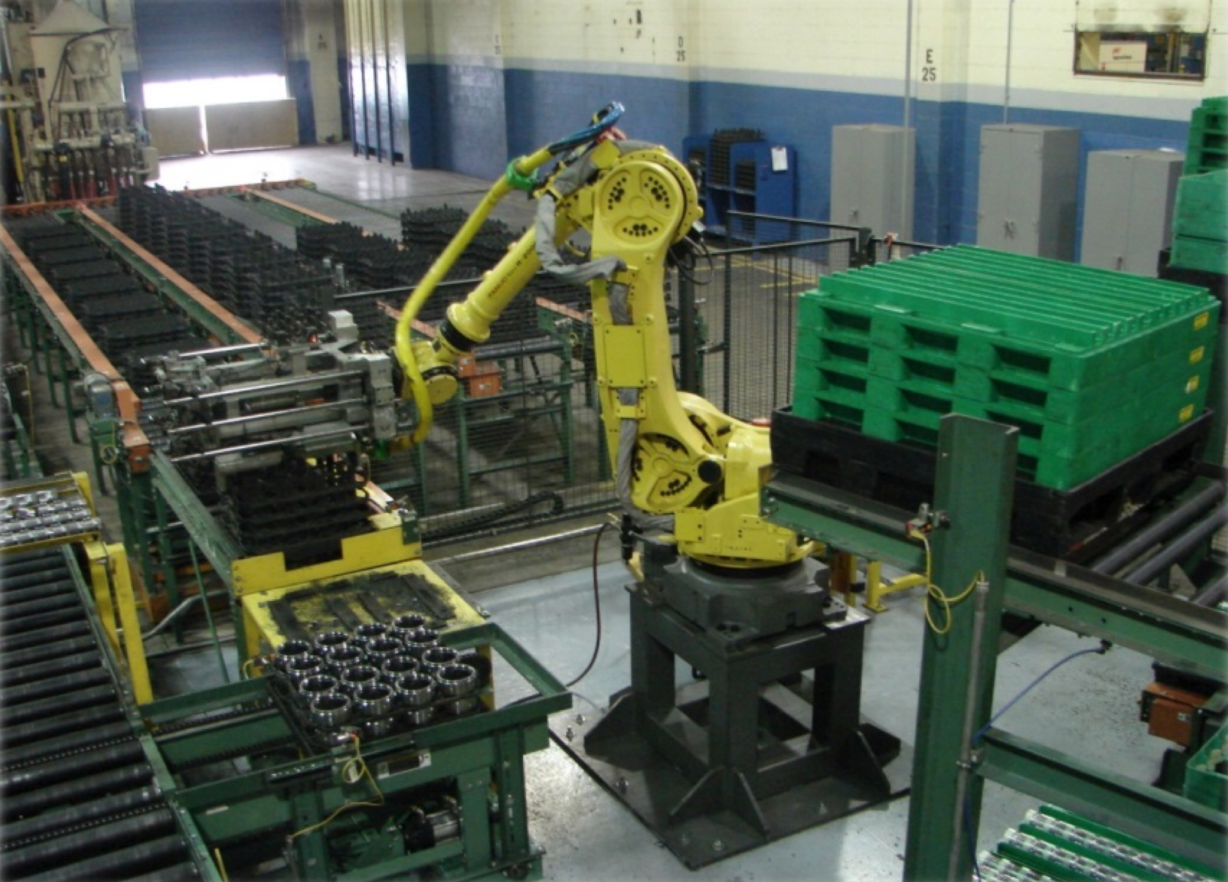
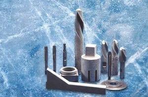
The gear featured in this article is internal with a 1.59 module or size of the gear tooth. A 1.59 module is equivalent to 16 DP, although it does not meet the definition of a fine pitch gear (20+ DP), at 16 DP, it presents a similar set of dimensional challenges. It is worth noting that all gear making is susceptible to nicks, dings, or damage. A soft handling, robotic system can be installed to eliminate the possibility of damaging the teeth (Figure 3). Green/pre-heat treated gears received in color-coded, returnable dunnage is a good means of ensuring product is never mixed. The dunnage is then placed on a gravity-fed rail system that transfers it to the robotic cell. The robot has two interchangeable tools designed to pick and place the top layer of the dunnage in a designated area of the cell. The PLC program then changes the tooling, which will pick and place the heat-treat fixture into the heat-treating cell. The robot then changes the tooling to soft handle, pick, and place the parts on the fixture. This is repeated multiple times until the fixture is full and ready for the next step of the process. The robot is repeatable and reproducible, eliminating operator fatigue and possible errors for heavy and light components susceptible to handling damage.
Thermal Processing
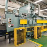
The components have been racked and are ready to enter the process cell. The first phase is pre-cleaning. This is an important aspect of the process in that any residual petroleum-based cutting fluid or rust preventative may not be compatible with the heat-treat process and could result in an oxide or chemical stain that inhibits the carbon from diffusing into the surface. The second phase is pre-heat. During this phase, a desirable pre-oxidation may be part of the process to help facilitate carbon penetration. At temperatures below Ac1 (temperature of steel when it starts to transform into austenite), protective atmospheres of inert nitrogen may be used. As stated in the introduction, extra care must be taken to control the process time, process temperature, and process atmosphere. In a continuous pusher furnace, process time is determined by taking the number of trays/fixtures, tray positions, and rows in the furnace and dividing the value by the total time necessary to soak for a determined period of time, which is temperature dependent, e.g. the higher the process temperature, the shorter the cycle time. This becomes the “push rate,” which determines throughput.
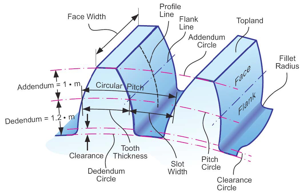
Figure 4 is gear geometry nomenclature. For more detailed definition see “Nomenclature and Definitions” in the appendix of this article.
Statistical Analysis
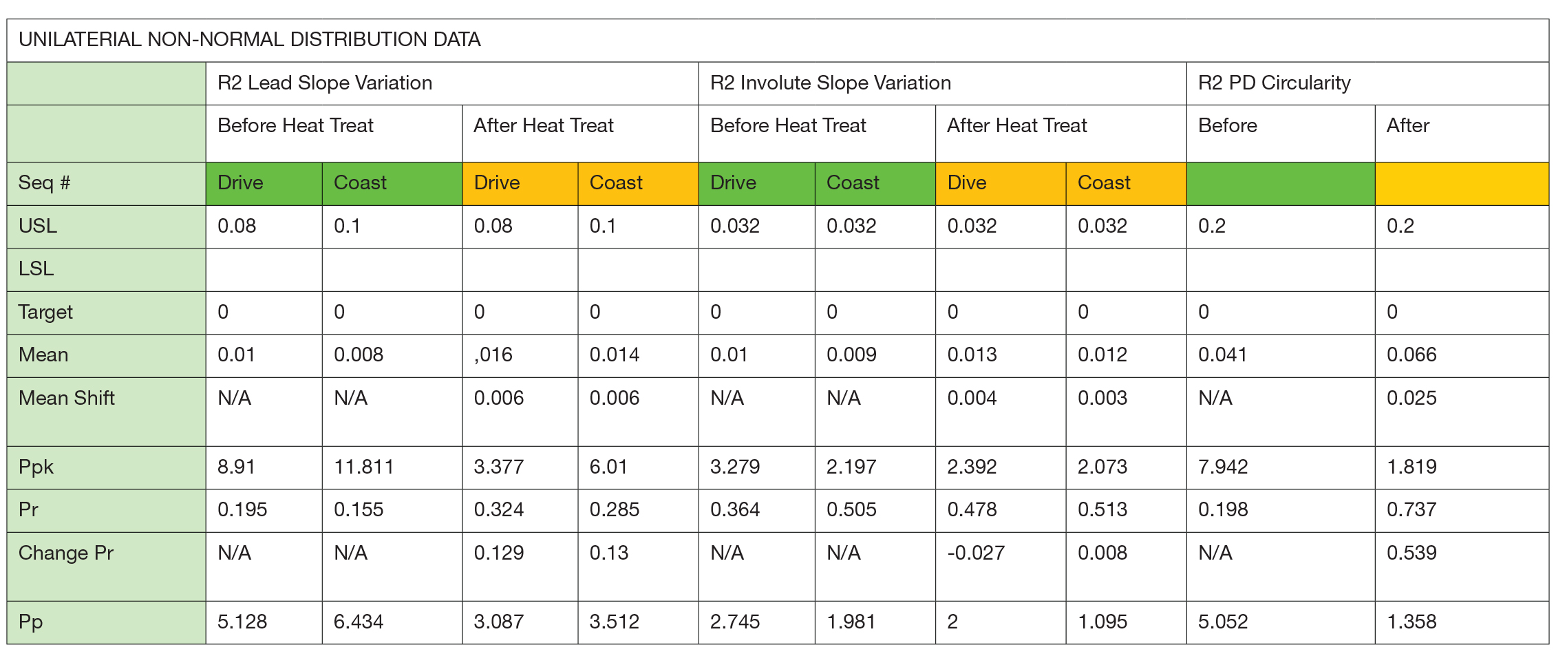
Unilateral tolerancing (Figure 5, Figure 6, Figure 7) is asymmetric and specifies a deviation in one direction, plus or minus. Unilateral tolerances for this article were evaluated as “non-normal” distributions. This article has upper specification limits, with zero being the target. As a result, Ppk (performance statistics) are based on Z-Upper, the value of the USL – Xbar/3 sigma. Pr, or percentage of tolerance or variation, is based upon 6 sigma/tolerance, and Pp or process potential is based upon Tolerance/6 sigma. Dimensional test are as follows:
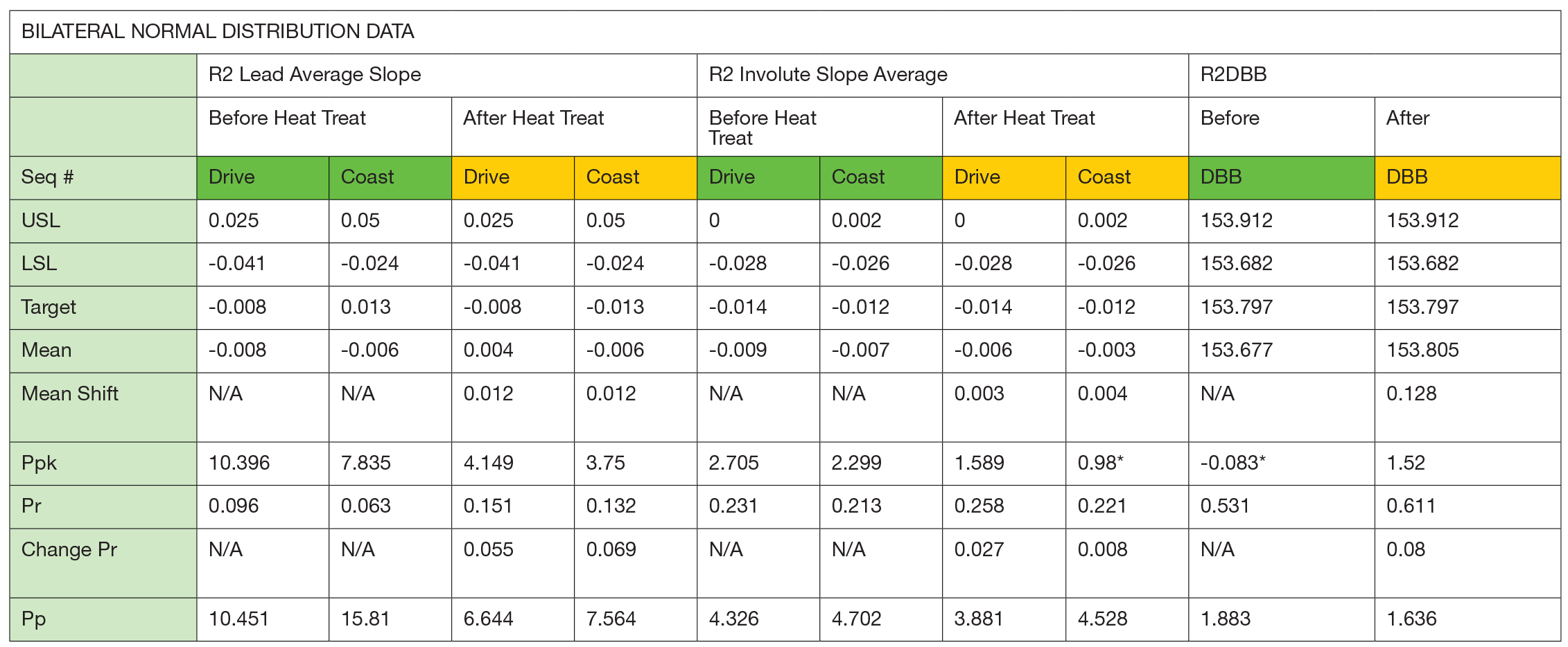
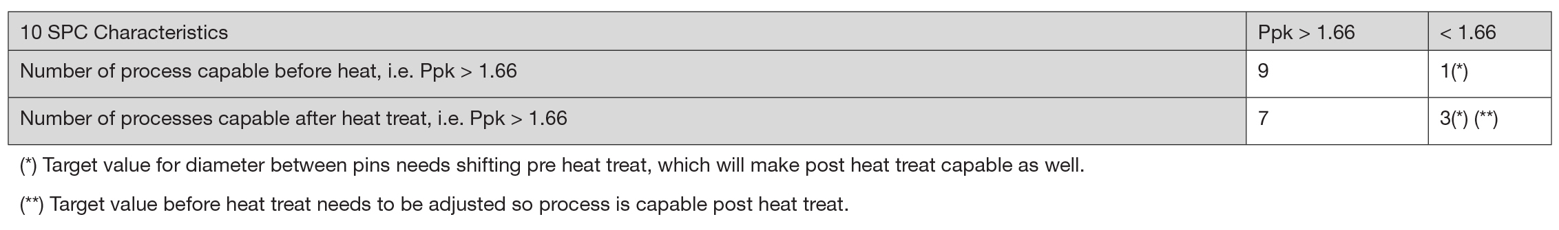
Bilateral tolerancing — symmetric tolerancing that has two equal plus-or-minus deviations from nominal — can exhibit a normal distribution, and in this article, tests for normality were conducted, and the process can be centered and variation reduced. Ppk is a measure of location and variation. Ppk is calculated by Z-min, which is defined as the minimum value between Z-Upper (USL – Xbar/3 sigma) or Z-Lower (Xbar – LSL/3 sigma) If the Xbar is greater than the nominal target value, default to Z-Upper, and if less than Xbar, target Z-Lower. Ppk can be a negative number. Pp is a measure of variation only and is always a positive number. Pr is a measure of variation only and is the percentage of the tolerance used in the distribution. Pr is always a positive dimension.
As a result of the before and after heat-treat test results, the pre-heat slope drive average target value was shifted by 0.006 mm to center the process resulting in a post Ppk > 1.66, The coast involute slope average pre heat treat nominal was shifted by 0.009 mm to center the process, resulting in a post heat treat Ppk > 1.66. Diameter between balls pre heat treat target value was shifted by 0.008 mm, resulting in post heat treat Ppk > 1.66.
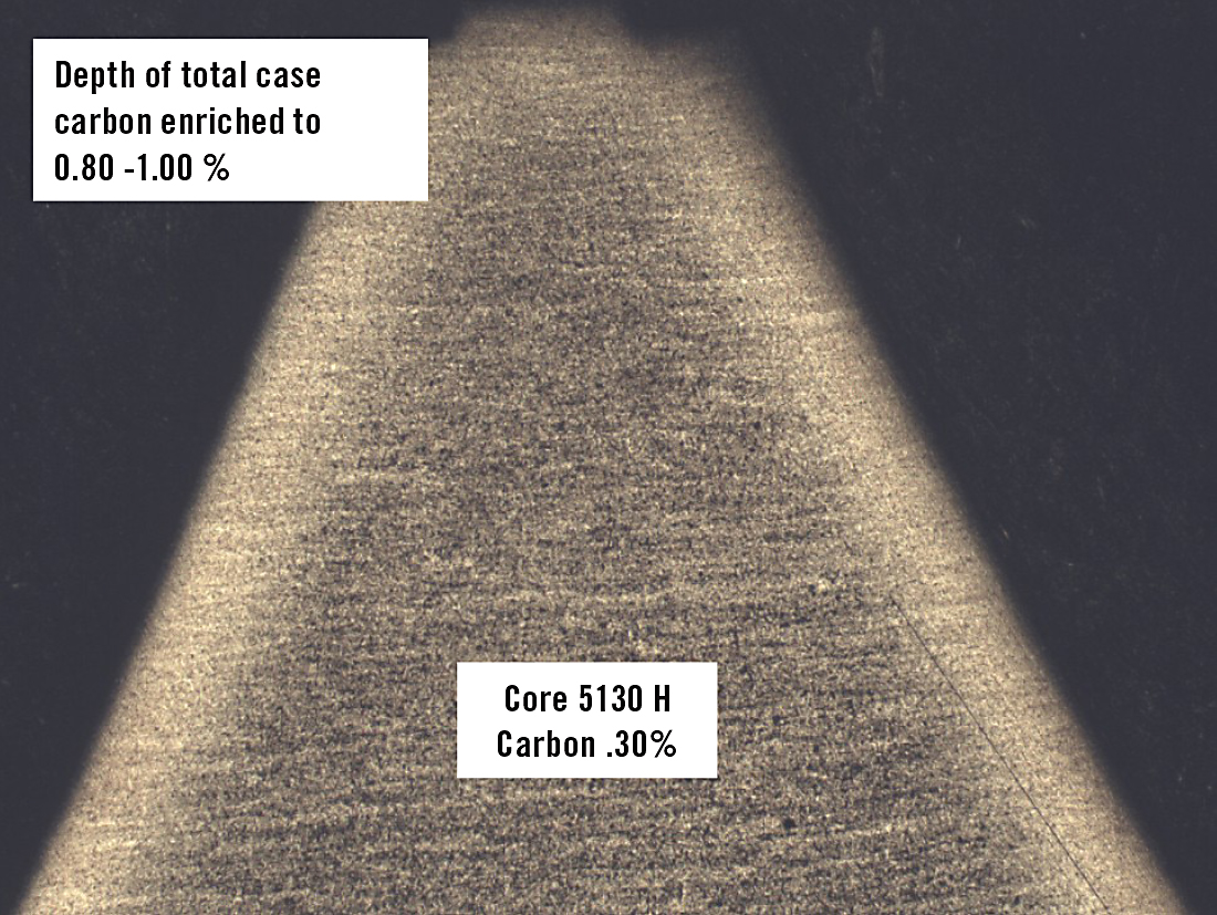
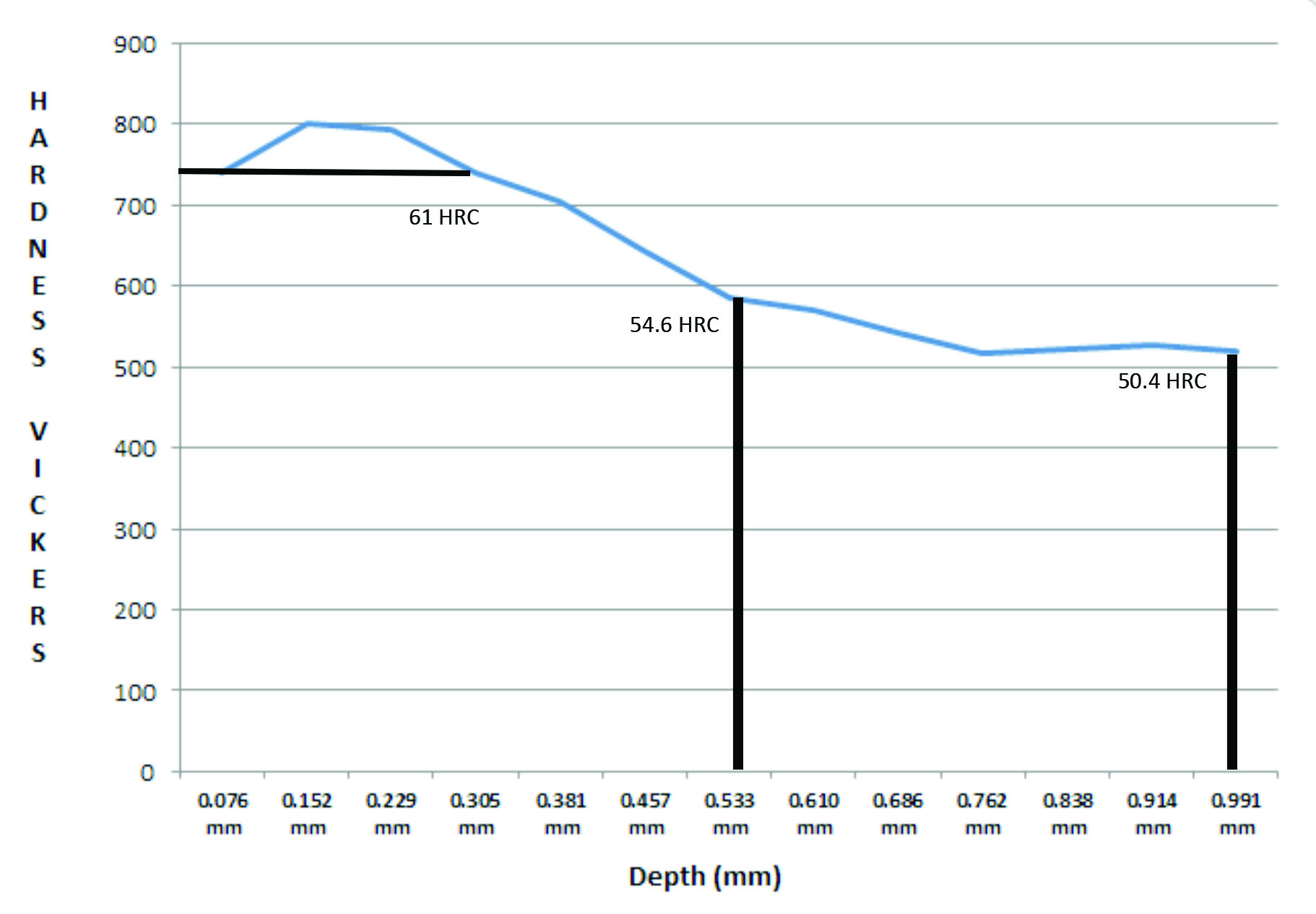
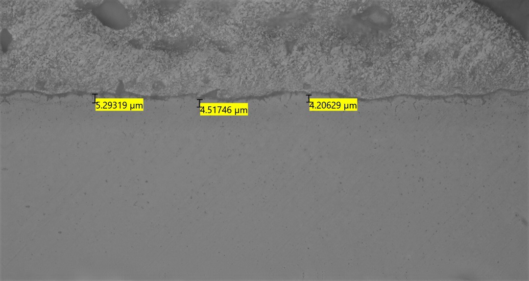
Case depth specifications are critical when case-hardening a gear. Tooth size and geometry are taken into consideration, because the base chemistry will be altered on the surface of the gear during the carburizing portion of the heat-treat process. When parts reach carburizing setpoint temperature, the atmosphere is carbon enriched to achieve equilibrium of about 0.90 percent carbon. The base material core properties are not affected, so the carbon remains the original 0.30 percent. The outer layer morphology will be changed to 5190H according to the depth of carbon penetration. Total case depth is a visual measurement of the depth of carbon penetration (Figure 8). The “effective case depth” is derived from testing microhardness traverse indentations at various interval depths to a given hardness value on a properly prepared test specimen using a “Vickers” diamond, pre-determined gram load, preset dwell time, and denoting its symmetry and size (Figure 9). The harder the carbon-enriched layer, the smaller the diamond penetration. Test methods for microhardness testing are governed by ASTM E-384.
Metallurgical specifications and test results derived from 30 datapoints are outlined in Figure 10.
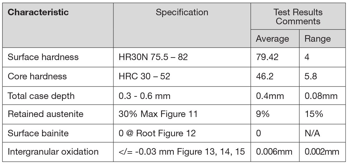
Metallurgical photomicrographs (referenced in Figure 10)

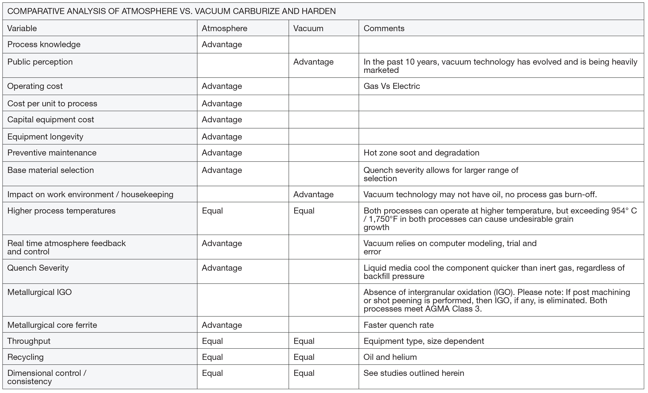
Atmosphere carburizing, oil quenching, and tempering are parts of the cost effective, viable process for gears that requires strict, repeatable, and reproducible metallurgical and dimensional controls. The process allows the design engineer more choices in raw material selection worldwide. The process is mature, robust, durable, reliable, and repeatable. Based upon the author’s 40-plus years of manufacturing, engineering, and process development experience, the comparison table (Figure 16) rates the two processes.
Appendix
Nomenclature and definitions:
Hertzian contact pressure: Occurs in the center of the contact surface of two bodies that are pressed together.
Lead Average of the high and low points OR total helix deviation from optimal on the flank of a gear tooth OR average of the best fit of slopes of individual traces, i.e. accuracy of helix angle accuracy.
Lead Variation: Difference from high to low points from optimal on the flank of a gear tooth OR the variation within one particular inspection trace comparing the difference between highest and lowest point.
Lead Measurement: The method used to measure helix angle accuracy both and angle and form.
Involute Average of high and low points from start to end of active profile.
Involute Variation: Difference from high to low from optimal from the start to end of active profile.
Lead Crown: Highest point on flank of gear tooth.
Involute Crown: Best fit curve or profile barreling on active profile of gear tooth.
Flatness: A zone between two parallel planes within which a surface must lie. Since flatness is applied to an individual surface, this tolerance does not need to be related to a datum.
Roundness has four primary assessments:
- Minimum radial separation with concentric circles enclosing the least radial separation.
- Minimum circumscribed circle, which is the smallest circle fitted around a circular profile.
- Referenced circle, which is the measured circular profile that calculates the minimum sum of all profile deviation.
- Maximum inscribed circle, which is the largest circle fitted around a circular profile.
Circular tooth thickness: Length of the arc between the two sides of a gear tooth on the pitch circle. Can also be measurement or diameter between balls or pins.
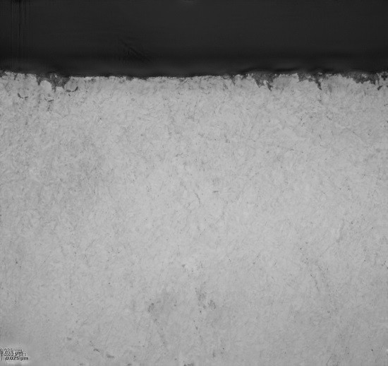
Surface bainite: A transformation product in solid steel developed from austenite at temperatures intermediate between those where pearlite and martensite form. Lowers base material toughness. Quench rate too slow plus high percentage of carbon.
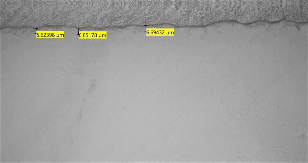
Intergranular oxidation (IGO): A phenomenon that occurs as a result of gas carburizing due to the process-gas decomposition. Primary concern of IGO is focused in the gear root at 60 degrees from the midpoint, which could lead to intergranular fracture when the gear tooth bends or deflects. See AGMA 923 B05 for grade definitions.
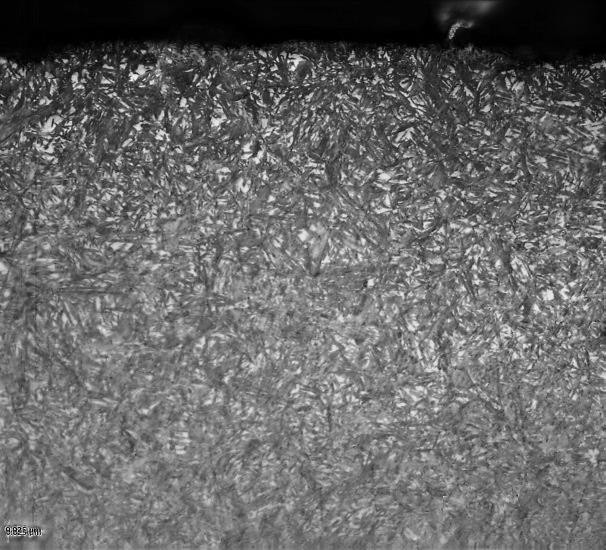
Retained austenite: A solid solution of one element in the face-centered cubic iron; unless otherwise specified, generally considered carbon. This phase is unstable and can be brittle, leading to sub-surface fatigue. Quench rate too slow plus high percentage of carbon.
Carbide networking: High carbon content plus excessive soak times plus temperature.
Core ferrite; see core hardness: Solid solution of carbon in body-centered cubic iron, a constituent of carbon steels. Essentially carbon-depleted iron.
Hardenability of steel definition: The property of steel that governs the depth to which hardening occurs in a given cross section of a material.
Methods and References
- American Gear Manufacturers Association, Materials and Heat Treat Specification 923 B05
- American Gear Manufacturers Association Nomenclature / Definitions
- Six Sigma Methods
Metallurgical Preparation and Testing
- Metallographic preparation: ASTM E883 and E407
- Microhardness testing: ASTM E384
- Metallographic definitions: ASTM E7
- Decarburization: SAE J419
- X-ray measurement of retained austenite: ASTM E975
- Case depth measurement: SAE J423
- Hardness testing: ASTM E18
Microstructure Analysis
- Metallographic Technique, Metals Handbook, ASM 9th Edition, Volume 9 pages 165-196
- Metallographic Technique, Metals Handbook, ASM 8th Edition, Volume 8, pages 61-70
- Martensitic Structures, Metals Handbook, ASM 9th Edition, pages 668-672
- Martensitic Structures, Metals Handbook, ASM 8th Edition, pages 197-199
- Bainitic Structures, Metals Handbook, ASM 9th Edition, pages 662-667
- Bainitic Structures, Metals Handbook, ASM 8th Edition, pages 194-196
- Case Hardening Steel, Metals Handbook, ASM 9th Edition, pages 217-229
- Case Hardening Steel, Metals Handbook, ASM 8th Edition, pages 84-85
- Retained Austenite, Metals Handbook, ASM 9th Edition, page 221
- Carbide Networks, Metals Handbook, ASM10th Edition, page 370
- Gas Carburizing, Metals Handbook, ASM 10th Edition, pages 312-324
- Intergranular Oxidation, Metals Handbook, ASM, 9th Edition, page 222
- Carbide Morphology, Metals Handbook, ASM 9th Edition, page 220
- American Gear Manufacturers Association, AGMA Metallurgical Specifications for Steel Gearing, 923 B-05


 general practice for CQI-9 and AMS2750E")


