


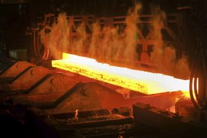
Case hardening by carburizing is the most common heat treatment in mass production, which relies on atmosphere or vacuum carburizing followed by oil or gas quenching and finally by tempering. Parts being heat-treated undergo the process in a configuration of a batch that consists of hundreds or thousands of pieces. It’s obvious a particular part achieves different process parameters in terms of temperature, atmosphere, and quenching depending on its position within the batch. Parts from the batch outside get a temperature sooner, a richer atmosphere, and more effective quenching than parts within the batch center. It leads to large result variation on parts within the batch, making an effective case-depth deviation as much as about 50 percent nothing unusual. Similarly, the hardening distortions are unpredictable and unrepeatable.
Modern industry requires more precise and repeatable results, which become out of the range of traditional technologies and equipment based on the batch method. Elimination of batches and a focus on an individual part is the only way for considerable improvement of the situation.
The article will introduce the first operational system for a truly single-piece flow method of case hardening by low-pressure carburizing and high-pressure gas quench. The system treats every single part the same way and provides the same process parameters, which results in extremely accurate and repeatable effects. Quenching of a single part in a specially designed chamber allows for control and significant reduction of distortions so much that some hard machining operations can be eliminated, as well as press quenching. The single-piece flow heat treatment method corresponds well with a manufacturing chain and can be directly integrated into in-line manufacturing, cooperating directly with machining centers. In such a case, materials handling and logistics are excluded, which saves cost and time.
The results achieved on a series of automotive gears prove outstanding accuracy and repeatability with significant distortion reduction. Also productivity and process costs are competitive. All proven advantages and savings make the single-piece flow case hardening system a sign of incoming revolution in heat treatment.
Introduction
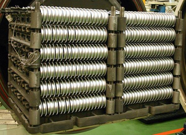
In traditional case-hardening systems, parts are configured and processed in batches on special fixtures (Figure 1) and undergo the whole case-hardening process in such a configuration. This means each part in a batch is affected by the process conditions in a unique manner based on its position within the batch. Each part is affected differently regarding the heating rate, composition of the process atmosphere, and intensity and direction of the cooling medium. There is no doubt the parts in the outer layers of a batch are heated more quickly and to a different temperature (according to the temperature distribution within the batch), as the atmosphere around them is “richer,” and they are quenched more intensely, compared to the parts toward the center of the load. The result is that parts inside the batch have different physical and metallurgical properties than those on the outside of the batch, e.g., surface and core hardness, microstructure, and especially the effective case depth [1][2]. That’s why forced and accepted industry requirements of case depth variation are ±30 percent, which even for industry is very, very tolerant.
Non-uniform quenching results in temperature gradients within each part resulting in thermal stresses and a non-uniform transformation of the microstructure. This ultimately results in large deformations of the part being quenched. Quenching results are made even worse by the fact that the quenching stream within the batch is dispersed and each part is cooled differently based on its position within the batch. A critical summary of batch 2D quenching (especially oil quenching) shows it is an uncontrolled and non-uniform process, producing great deformations within each part and little consistency within the batch. Distortions have to be removed by final machining or other correction methods. Costs of these operations are huge — for the German industry, it’s about 2 billion euros a year [3], while a global estimation is about 20 billion euros.
Material handling of batch loads is typically complicated and costly. Gears are produced individually. After being shaped, they are collected, packed, protected, and transported to the case-hardening department (captive) or to an external firm (commercial), which can sometimes be hundreds of kilometers away. The gears are then unpacked, washed, and racked in order to form batches on fixtures designed specifically for the case-hardening process. Following an oil quench, the parts are washed again, dismantled, packed, protected, and transported back to the mechanical processing department. The whole undertaking may be divided into more than 10 operations and take days. These handling costs consume considerable resources, including time, materials, money, and damages.
Batch processing also has other quality, material-handling, and cost pitfalls. For example, monitoring and reporting on the case-hardening process are for the entire batch and not for individual pieces within the batch. That makes it difficult, or even impossible, to introduce and implement tighter quality standards.
The previously mentioned weaknesses come from the batch method and cannot be overcome. If more improvement is necessary in terms of a result’s precision and repeatability, distortion’s reduction and control, and in-line production’s integration, the only way is the real single-piece flow heat treatment, which guarantees ideally the same process parameters for every single part in a series.
A single-piece flow case hardening by LPC and HPGQ
Figure 2 shows a vacuum furnace for case hardening of gears or rings using LPC and high pressure gas quench (HPGQ). This system fully meets the criteria of a single-piece flow method and has all the accompanying advantages contrary to other solutions [4][5]. The furnace consists of three horizontal chambers: the first one for heating up, the second for low pressure carburizing, and the third for diffusion and pre-cooling before quenching. Additionally, a separate loading chamber and a quenching chamber (that doubles as an unloading chamber) are connected. Parts are transported between chambers by two vertical transport elevators attached to each side of the system.
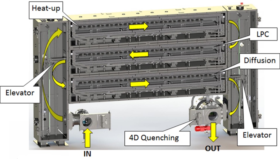
The single-piece flow process runs in the following manner:
- A single gear is placed inside a loading chamber.
- It is transported and loaded into the heating chamber.
- A walking beam mechanism indexes the gear through all the positions until the gear reaches the target carburizing temperature.
- The gear is transported and indexed through the LPC where the surface is saturated with the right amount of carbon.
- The part is transferred and indexed through the diffusion chamber where the desired carbon profile is achieved, and the temperature is decreased before quenching.
- The gear is transferred to the gas cooling chamber where it is quenched.
- The gear is removed from the quenching chamber and is ready for temper.
Each gear follows in sequence and is processed the exact same way, with the exact same process parameters, guaranteeing the highest level of precision and repeatability.
Lean Manufacturing
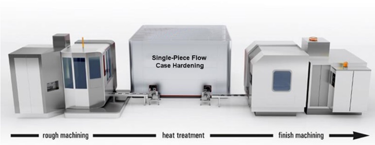
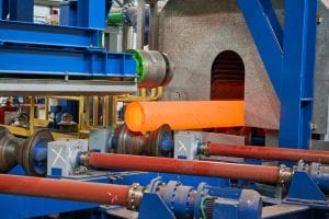
The new concept of single-piece flow case hardening is intended to be installed and operated directly on the manufacturing floor next to a CNC machine and was designed so that its footprint was similar to a CNC machine (Figure 3). It can be installed on new production floors or at sites previously occupied by other machines, including CNC machines. A newly machined gear can be introduced into and released from the case-hardening system as frequently every 30 to 60 seconds (throughput up to 1 million parts a year). The system can be completely integrated into the continuous, lean production manufacturing line, thus eliminating many, if not all, batch material handling steps. It corresponds very well with an idea of Industry 4.0, too.
Also, please notice the system does not use fixtures for load racking. As noted previously, this helps reduce operating costs, including the cost to purchase and replace fixtures, as well as the consumption of energy.
The first, operational single-piece flow case hardening system
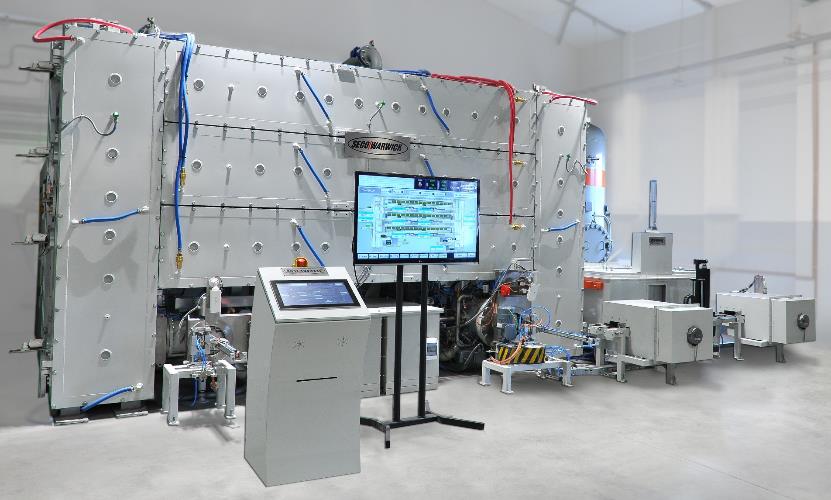
The first complete and automated single-piece case-hardening line has been developed based on the furnace UniCase Master®. The line consists of the main furnace and accompanying devices and systems necessary for the process realization from beginning to end, among other things: manipulators, a tempering furnace, cooling chambers, a gas system, a vacuum pumping system, etc. (Figure 4 and Figure 5). The line has the following technical parameters:
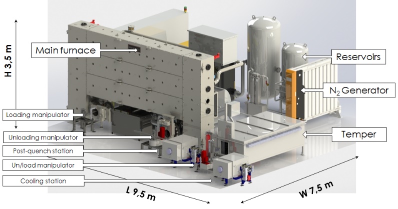
Figure 4: A complete, automated line for single-piece flow case hardening.
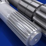
- Part diameter: 8 inches / 200 millimeters
- Part height: 2 inches / 50 millimeters
- Part mass: 8.8 pounds / 4 kilograms
- Number of positions in a process chamber: 15
- Tact: min. 30 seconds
- Temperature: 2,012° F / 1,100° C
- Quenching: 10 bar N2
- LPC (FineCarb): acetylene
- Installation area: 24.6 x 31.2 feet / 7.5 x 9.5 meters
- Power: 150 kW
The carried-out tests have confirmed the correctness of the technical solutions and the operating and technological parameters. Transport mechanism reliability and full control of the technological result have been achieved. The system has been tested in hundreds of tests over a wide range of parameters: at temperatures between 840 and 1,060° C and effective case depth within 0.30 to 1.5 mm.
A high-result precision and replicability, as well as a significant reduction of hardening deformations have been obtained.
Precise carburizing (LPC)
To confirm the accuracy and repeatability of carburizing (LPC), two types of tests were carried out on a part series. The first test consisted of checking the evenness of carbon transfer from the atmosphere to the part surface through a measurement of the mass of carbon introduced during the process (gravimetric method). To this end, the parts were weighed before and after the process; the weight increase reflects the absorbed carbon mass. The test was carried out on wheels with a diameter of 96 millimeters and a mass of 550 grams; their weight was specified with an accuracy up to ±2 milligrams. Figure 6 shows the diagram of the weight increase measurements for the part series. Except for the first three wheels that were introduced to the empty device and that show slightly greater weight increase, the whole series ranges from 583 to 595 milligrams. This means accuracy and repeatability unattainable in no other method, i.e. ±1 percent.

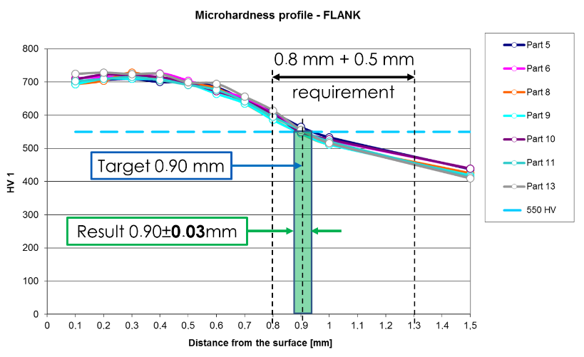
However, the same carbon absorption does not have to mean the parts have obtained the same carbon profile and hardness profile. Therefore, to confirm the results, the second type of test measured the hardness profile. The test was carried out on gear wheels with a diameter of 180 millimeters, carburized and quenched within the effective case depth of 0.9 millimeters (550 HV). The results are shown in Figure 7. Of the wheels selected from the series, the correct hardness profile was obtained and the effective case depth was 0.90 millimeters with ±0.03 millimeters, i.e., repeatability has been ±3 percent.
This result is unattainable with traditional methods. In addition, special attention should be paid to make sure the hardness profile measurement accuracy itself is stuck with the comparable error, so in all probability, the repeatability of actual results is even better.
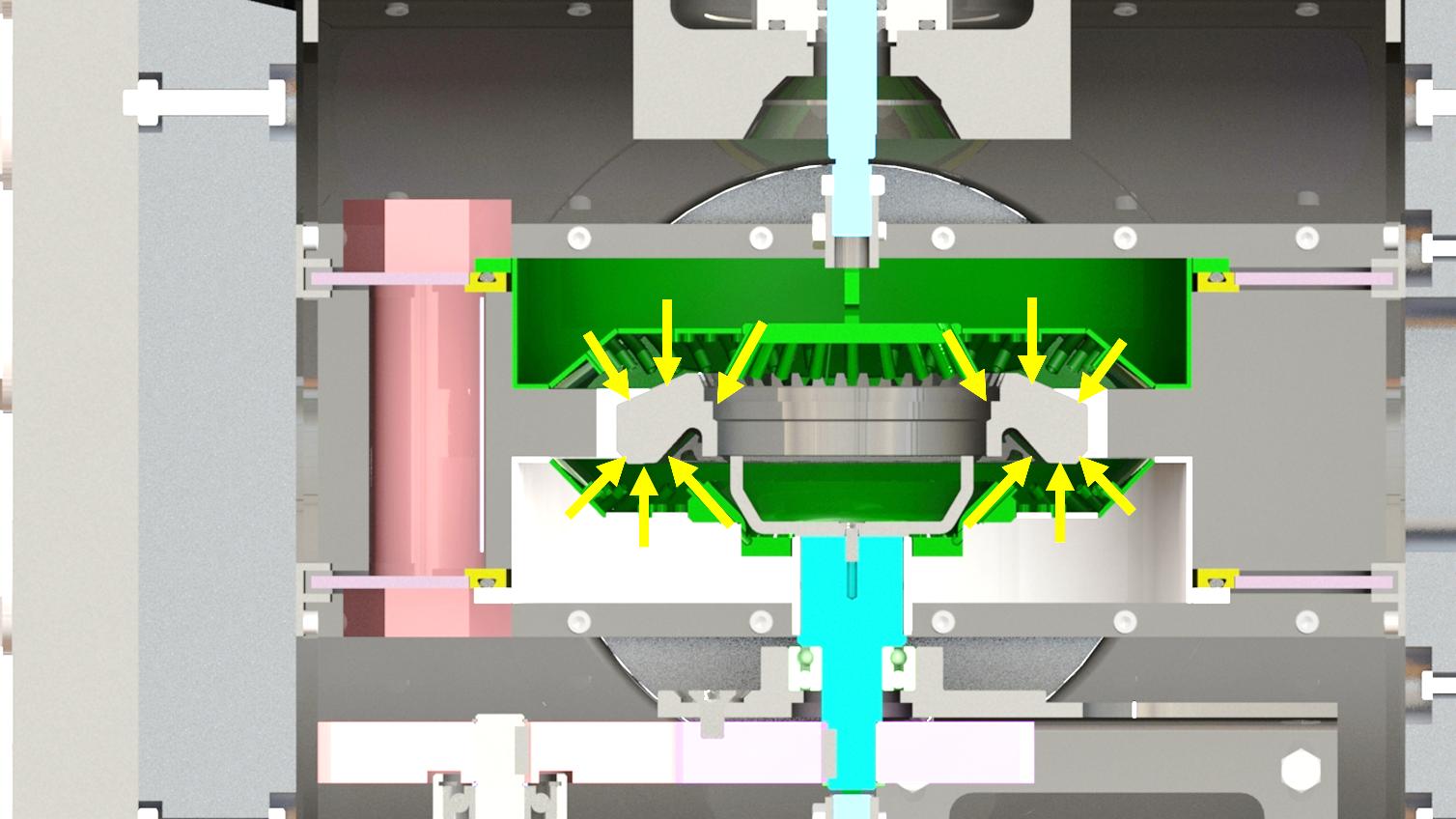
4D Quenching®
The new concept also allows for significant improvements in the quenching process, specifically the reduction of distortion. This is done primarily using a high-pressure gas quenching system installed in the quenching/unloading chamber (Figure 8). The system uses a proprietary arrangement of cooling nozzles that surround the part and ensures a uniform flow of cooling gas from all sides: top, bottom, and side. We refer to this as “3D” cooling. In addition, a table spins the part, further enhancing quench uniformity. We refer to the spinning motion as the fourth dimension, allowing us to “4D” quench gears for the best possible uniformity. The cooling nozzles allow us to achieve up to 10 bar quenching results — comparable to oil quenching — without the use of helium. Because the cooling nozzles can be adjusted to fit the gear’s precise size, quenching is optimized, and distortion is significantly decreased.
Deformation Reduction
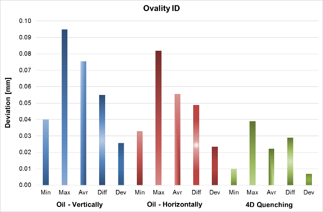
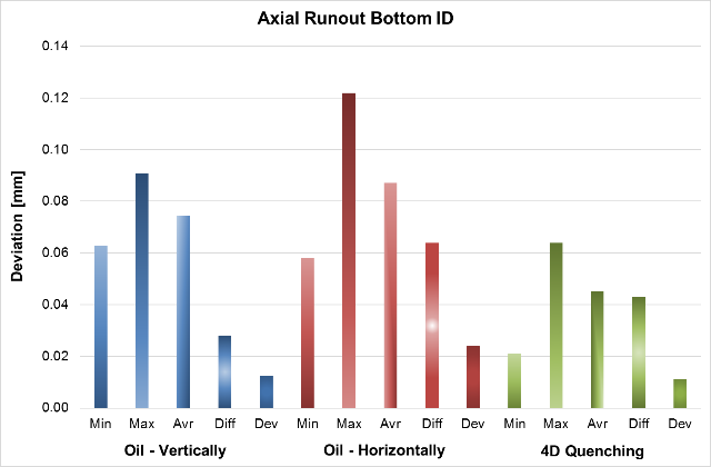
In order to check and compare deformation, tests of detail quenching in the 4D Quenching chamber are compared with the traditional method of batch in oil in two positions: vertical and horizontal. The tests were carried out on a series of hypoid gears (ring gears) with a diameter of about 200 millimeters (Figure 9). The gears were carburized and quenched to obtain an effective case depth of 0.8 millimeters (550 HV) and tempered at 180° C.
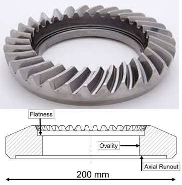
The deviations were measured in the following places (Figure 9):
- Flatness of top surface of the internal hole.
- Axial runout of bottom surface of the internal hole.
- Ovality of the internal hole.
The distortion-measurements summary is shown in Figure 10 in many ways, such as:
- Min: minimal value
- Max: maximal value
- Avr: average value
- Diff: Max-Min value
- Dev: standard deviation
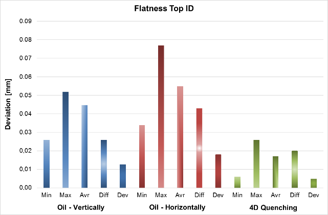
The flatness deviation for the vertical oil quenching has reached up to 25 to 52 micrometers and more, and 34 to 77 micrometers in the horizontal position. Larger flatness distortion in the horizontal position is very characteristic for directional, vertical parent of quenching oil flow. The same flatness deviations after uniform hardening in the 4D Quenching chamber obtained the results in the range from 5 to 25 micrometers, i.e. two to three times better. The variation of results measured by the standard deviation is up to five times more precise in the 4D Quenching comparing to traditional batch quenching in oil.
The ovality deformations after oil behave contrary between vertical: 40-95 micrometers and horizontal position: 33-82 micrometers. The horizontal position is preferred as slightly less prone to distortion, which is in relation to the oil flow vertical direction. Nevertheless the 4D Quenching reached ovality deviation from 10–38 micrometers, which is again two, three times less and more precise.
In the case of the axial run-out, the deformations are 56-120 micrometers for oil and 20-65 micrometers for the 4D Quenching chamber, i.e., two-times less.
In general, the possibility of a significant (double or even quadruple) lowering of the hardening deformations of parts in the individual quenching chamber (4D Quenching) has been confirmed, although these results are not final because they have been done as a first shot. Much better results are expected to be obtained while dedicated optimizing programs are applied in terms of design of the 4D Quenching nozzles and quenching process parameters. In many cases, final hard machining and press quenching won’t be necessary.
Summary
In turn, at the innovative system, single-piece flow — UniCase Master®, the technological result precision and replicability have reached an, as yet, unattainable level, while their dispersion has been reduced tenfold. However, the quenching chamber, 4D Quenching, allows for deformation control and reduction by several times. This results in a significant reduction of the finishing operation and its costs and, in many cases, its elimination. The integration of the heat treatment directly into the production chain eliminates the material logistics costs and shortens the production time, as well as allowing for traceability and an in-line check of each part during production.
The main benefits the single-piece flow case hardening can deliver are:
Single-piece flow:
- 10 times improved results precision and repeatability.
- 100 percent traceability, individual part monitoring, and reporting.
- 100 percent single part in-line testing after case hardening.
Lean manufacturing:
- 100 percent integration into continuous production lines.
- High throughput.
- Zero cost of material handling logistics.
- Zero cost of heat-treatment fixtures.
4D Quenching®:
- 2-4 times less distortion size.
- 2-4 times less distortion variation.
- 2-4 times less hard machining operation.
- Elimination of some hard machining operations and press quenching.
Low Pressure Carburizing / High Pressure Gas Quenching:
- Elimination of IGO.
- Fast high temperature carburizing (up to 5 times).
- Elimination of fire and explosion hazards.
- Clean and environmentally friendly production.
The solution determines a revolutionary direction of changes and development of heat-treatment technology and equipment for the modern industry and fully complies with present and upcoming requirements.
References
- MacKenzie S.D., Li Z., Ferguson B.L. “Effect of Quenchant Flow on the Distortion of Carburized Automotive Pinion Gears.” International Federation for Heat Treatment and Surface Engineering—IFHTSE, 5th International Conference on Quenching and Control of Distortion, European Conference on Heat Treatment 2007, Berlin, 25–27 April 2007.
- MacKenzie D.S., Kumar A., Metwally H., Paingankar S., Li Z., Ferguson B.L. “Prediction of Distortion of Automotive Pinion Gears during Quenching Using CFD and FEA”, Journal of ASTM International, Vol. 6, No. 1, 2009, 1–10.
- Thoben, K.-D.; Lübben, Th.; Clausen, B.; Prinz, C.; Schulz, A.; Rentsch, R.; Kusmierz, R.; Nowag, L.; Surm, H.; Frerichs, F.; Hunkel, M.; Klein, D.; Mayr, P.: “Distortion Engineering”: Eine systemorientierte Betrachtung des Bauteilverzugs. HTM 57 (2002), pp. 276-282
- Heuer V., Löser K., Schmitt G., Ritter K. “One Piece Flow: Integration of Case Hardening into the Manufacturing Line.” Conf. on Gears, Oct. 4–6, 2010, TUM Garching, Germany.
- IHI “In-Line Heat Treatment – Next Generation Heat Treatment Equipment.” IHI Engineering Review, Vol.44, No.2, 2011.


 general practice for CQI-9 and AMS2750E")


 steels")

