


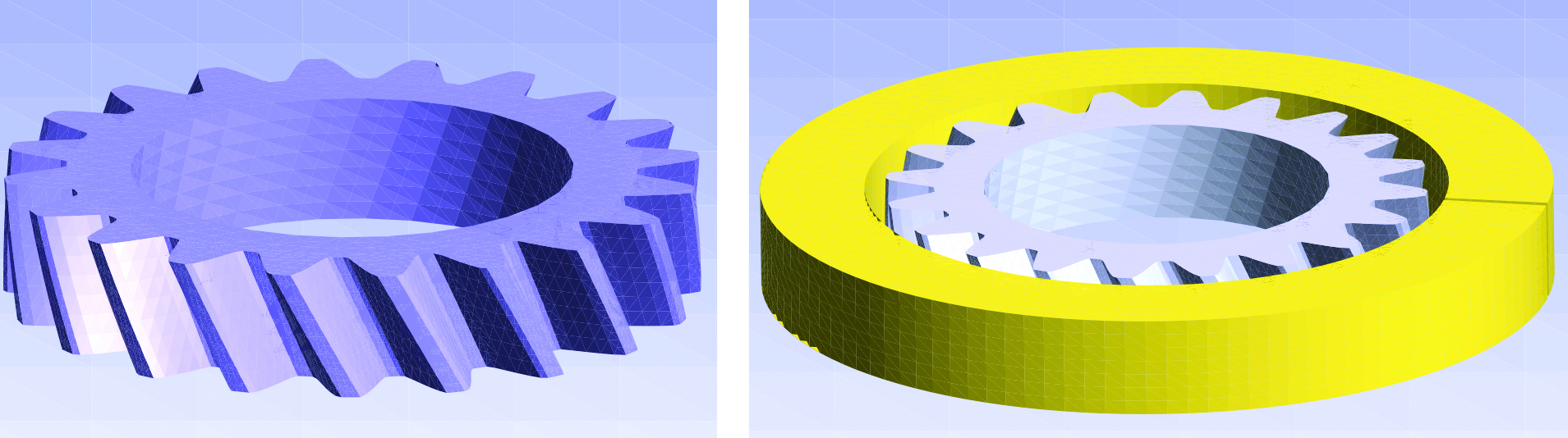
Every year since 2007, in June, a Modeling Week is held within the master program of the faculty of Mathematics of Universidad Complutense of Madrid (UCM) in cooperation with the Institute of Interdisciplinary Mathematics (IIM). During this week, students work in small groups on real industrial problems proposed by companies under supervision of one or two qualified instructors. As it was announced in 2013, the main purpose of the VII Modeling Week was to promote the use of mathematical methods and models in research, industry, innovation, and management in the knowledge economy. That year, Prof. Ortegón Gallego was invited to the seventh edition of this event as an instructor of one intensive course on the subject. “Some mathematical models and numerical simulation of heat treatment of steel.” During this course, the basic elements of the mathematical modeling of steel heat treating were described, a very simple 3D model was considered, without taking into account mechanical effects, for the heating-cooling industrial procedure applied to a helical gear (Figure 1). Then we perform some numerical simulations of this model according to the industrial heating technique: induction or flame hardening. To do so, we provide the students with some efficient noncommercial software packages, namely Freefem++ ([1]), MEdit ([4]) and gmsh ([6]).
Induction Hardening of a Helical Gear
There are many industrial hardening procedures for gears. This may depend on the size of the gear and on the final purpose of the workpiece. Induction hardening is a very general procedure widely used in the manufacture of gears. It can be applied in different manners ([2, 3, 12, 13]): (a) total induction around the workpiece, by the use of a coil surrounding the gear, or (b) local induction, by a tooth-by-tooth or a gap-by-gap techniques. In the first case, the encircling coil hardens the teeth from the tips downward. This pattern may be acceptable for certain types of gears such as splines and some gearings. Another induction technique producing a uniform contour hardening makes use of multi-frequency induction ([8, 9, 10, 12]).
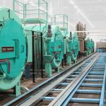
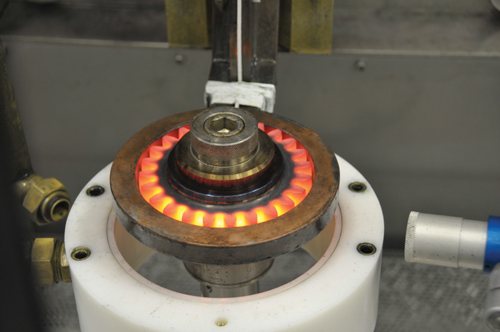
Depending on the workpiece geometry and size, the heating stage can be accomplished by an induction procedure or by direct flame. Induction techniques have been successfully used in industry since the last century. During a time interval, a high frequency current passes through a coil generating a high alternating magnetic field, which induces eddy currents in the workpiece, which is placed close to the coil. The eddy currents dissipate energy in the workpiece producing the necessary heating. Figure 2 shows an induction machine during the heating process applied to a gear; we can see the coil encircling the gear.

In this paper, we first consider a helical gear encircled by a coil (made of copper) as shown in Figure 1.
In our numerical simulations we have considered very simples models for both, induction hardening and flame induction of a helical gear. We have not taken into account mechanical effects describing the deformation of the workpiece and have kept only the dynamics of the austenite and martensite phase fractions. For more complete models, the reader is referred to [5, 8, 10, 11].
The mathematical model is divided into two stages: (a) heating, and (b) cooling. During the first stage, heat is produced by electromagnetics, letting pass a high frequency current through the coil. Here, the main variables are the electric potential, the magnetic potential, the temperature and phase fraction corresponding to the austenite transformation. At the beginning of the cooling stage, the current is switched off, and the workpiece is aquaquenched; main variables in this stage are the temperature and the phase fractions corresponding to austenite and martensite.
Building a 3D Triangulation of a Helical Gear
This section is devoted to the tetrahedralization of a helical gear. As it was stated above, we only use noncommercial software: Freefem++, TetGen ([7]), MEdit and gmsh.
Freefem++ is an integrated software for obtaining the finite element method numerical solution to boundary value problems for PDE of the elliptic type. By means of some semidiscretization in time scheme, Freefem++ may also deal with parabolic/hyperbolic evolution problems. This includes problems arising in solid mechanics, fluid mechanics, plasma physics, etc. This software can be freely downloaded from the Internet (http://www.freefem.org/ff++/index.htm) and it is fully documented ([1]). Though initially developed by O. Pironneau (Laboratoire Jacques-Louis Lions, Université Pierre et Marie Curie, Paris) in the 1980s, today it is maintained by F. Hecht, (Laboratoire JLL).
The first thing to do is a triangulation of the gear base. The base has two borders, namely, a tooth boundary and an inner circle. The way to produce the tooth boundary is to use a truncation of a cosine function oscillating around an outer circle. Let R be the outer circle radius, then a parametrization of the teeth is of the form
(1) 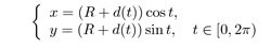
where d(t) is an oscillating function. For instance, if we want a m-tooth gear we may take
![]() (2)
(2)
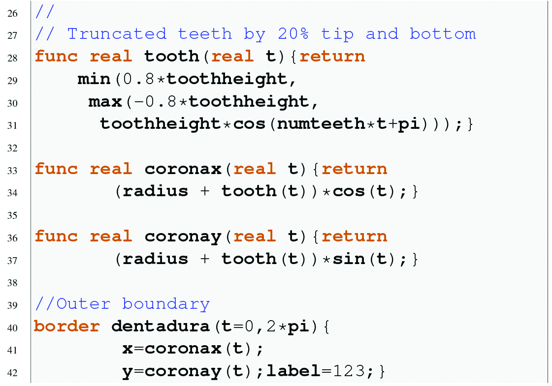
where l is the amplitude. Notice that, in order to produce a flat tip and bottom, we are also truncating the cosine by 20% its height and depth (Figure 3).

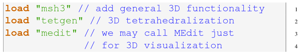
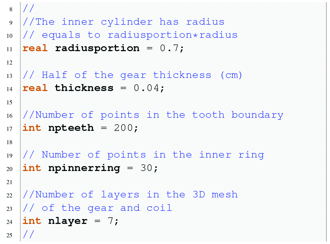
To start up, we load some necessary packages for 3D meshes.
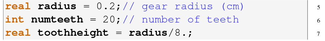
Then, we introduce some useful parameters.
Here comes the implementation of the functions like (1) describing the boundaries.
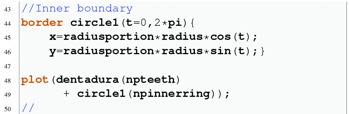
The inner boundary is just a circle.
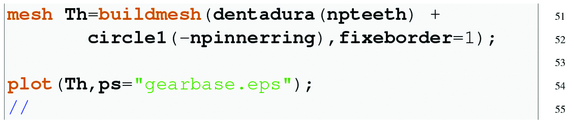
Finally, we generate the mesh. Notice that the number of the boundary points on the border circle1 is negative. This means that this arc is traversed clockwise and this results in a hole inside the domain. Also, the directive fixed border=1 means that during the automatic generation of the mesh, the original points on the boundary will be vertices of the triangulation. This is a very important issue when dealing with 3D meshes.
In order to build the gear mesh, we need to generate a 3D mesh of the whole workpiece boundary. In this case, we may distinguish four different surfaces: the base, the lid, the cylindrical inner wall and the tooth surface. Thus we build a two dimensional mesh in 3D for each of these surfaces. Then we stick out these meshes together forming a closed 3D mesh of the gear skin. This closed 3D mesh is used as a datum to generate the final gear tetrahedralization via TetGen.
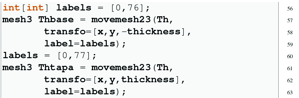
Here we transform the 2D mesh Th into 3D (flat) objects, namely the base (Thbase) and the lid (Thtapa). These surfaces are assigned the reference numbers 76 and 77, respectively.
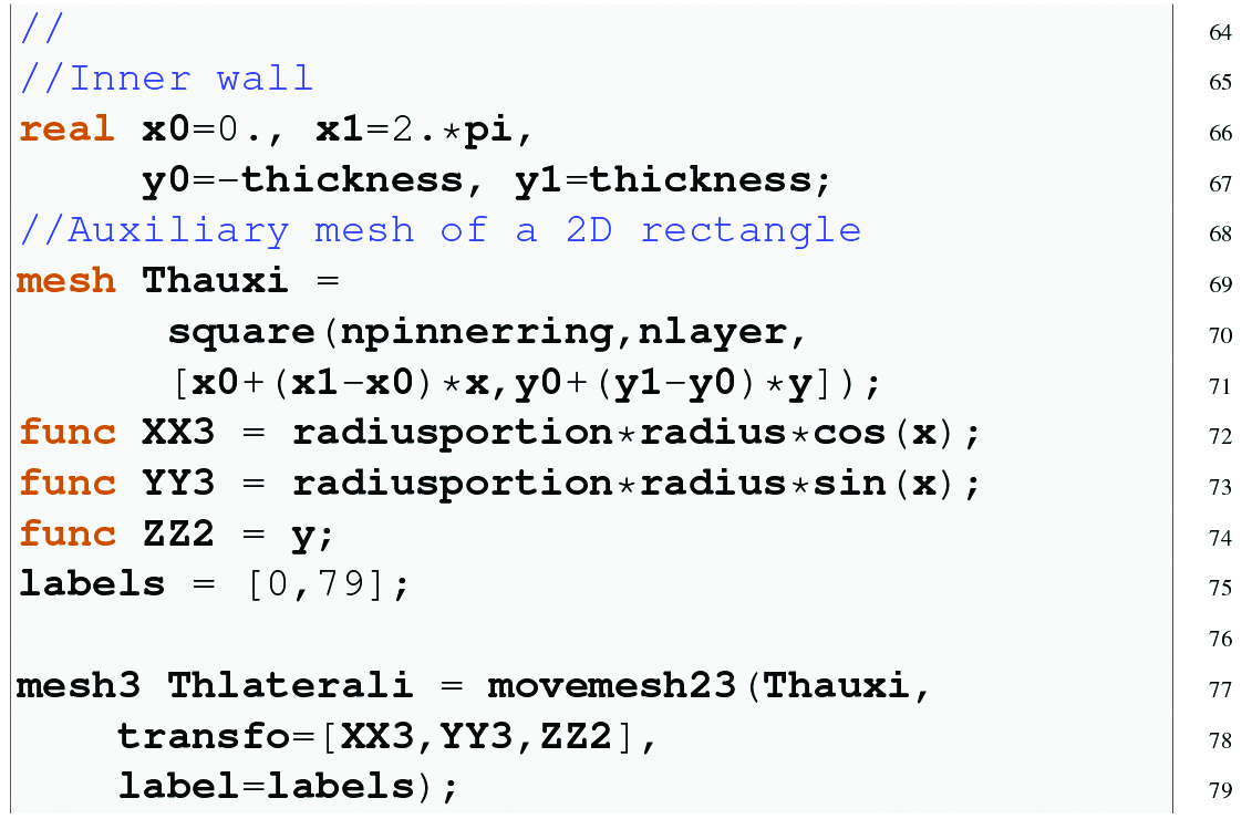
Then we generate the cylindrical inner wall. To do so, we first build a 2D rectangular mesh and transform it into the desired 3D mesh with reference number 79.
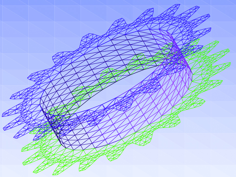
We stick these three meshes together, just to see that everything is OK. You can do so by saving this new mesh in a file that can be read with gmsh (or you just can call MEdit).
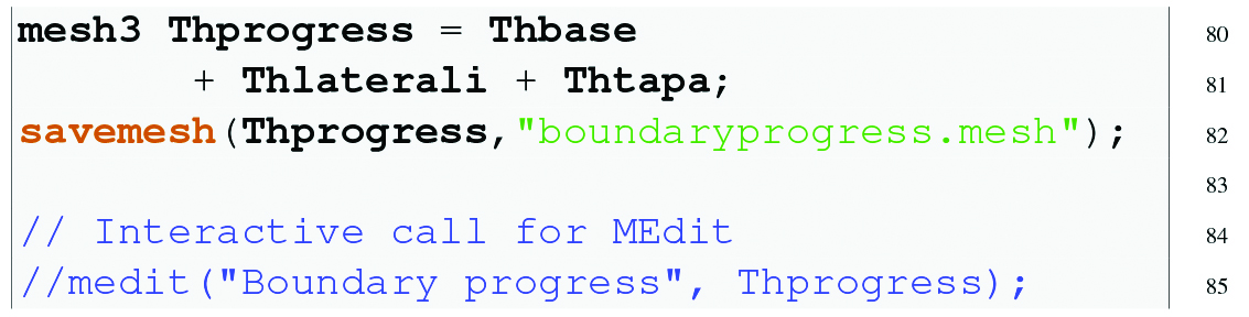
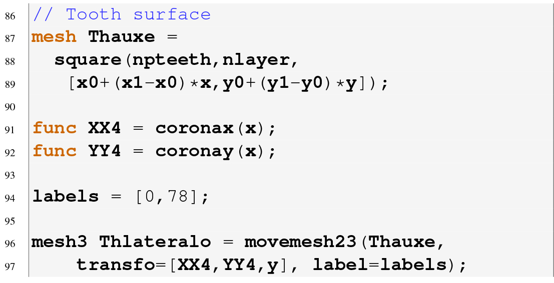
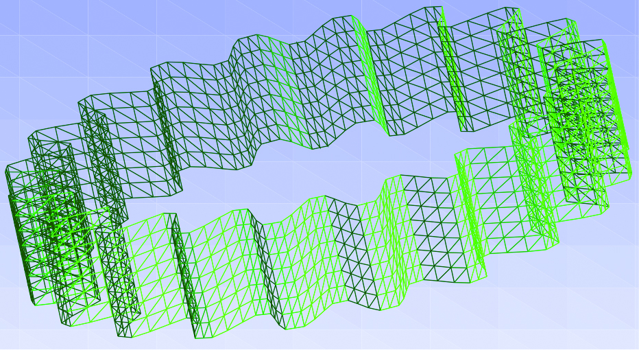
Figure 4 shows the resulting mesh Thprogress. In the same way, the lateral tooth surface is obtained by a suitable transformation of a 2D rectangular mesh (Figure 5).

Now we may stick out the four surface meshes together to produce the full gear skin (Figure 6). Notice that the contact points must fit in well.

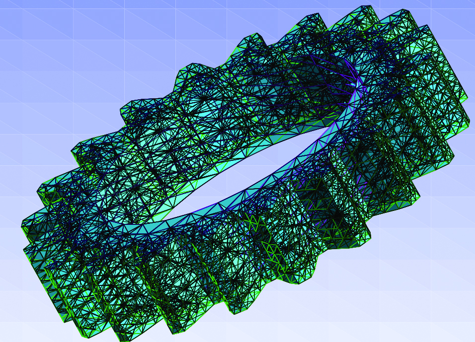
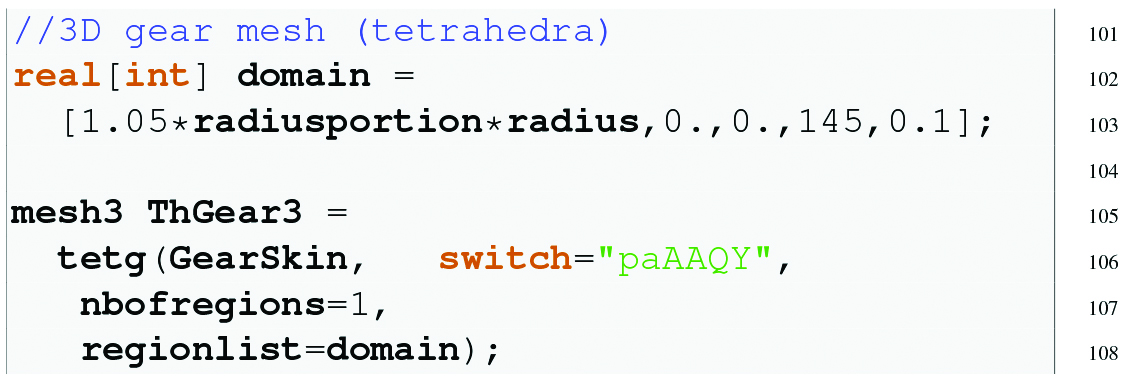
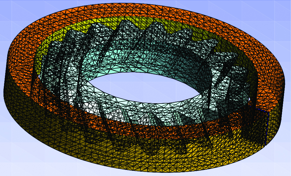
Using the 3D skin mesh GearSkin as a datum to TetGen, a straight gear tetrahedralization is generated (Figure 7).
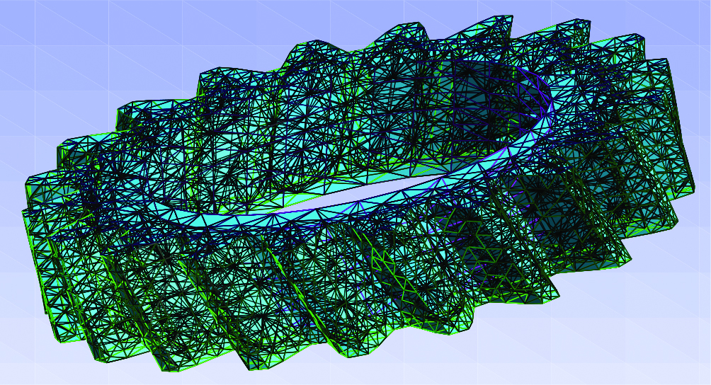
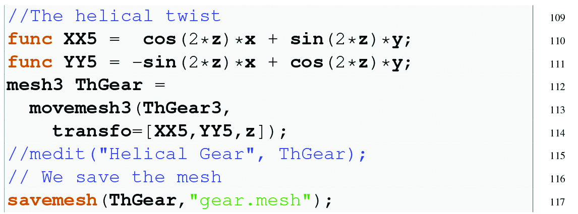
The final step is to produce a twist onto the straight gear mesh resulting in the helical gear mesh shown in Figure 8.
Remark: We have not explained every Freefem++ keyword appearing in these scripts. Most of them are self-explanatory but there are many fine points and keywords that admit their own different options. To learn more about this, the reader is referred to the various documentation available on the Internet (see, for instance, [1, 4, 6, 7]).
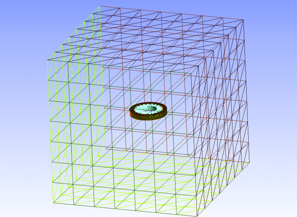
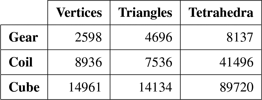
In the same way, we may generate a 3D tetrahedra mesh for the coil. Figure 9 shows the 3D skin mesh of the coil-gear setting. Finally, we need a large enough set containing both, the gear and the coil. This set is where the magnetic vector potential is to be computed during the heating stage. We may choose the shape of this set as simple as possible, for instance, a box or cube. Figure 10 shows the whole setting cube-coil-gear. Table 1 gives some information about the three generated meshes. It took Freefem++ 0.016275 seconds to compile the script and 2.92382 seconds to execute it on a MacBook Pro, taking into account the time spent on transferring the mesh files to the hard disk.
Numerical Simulations
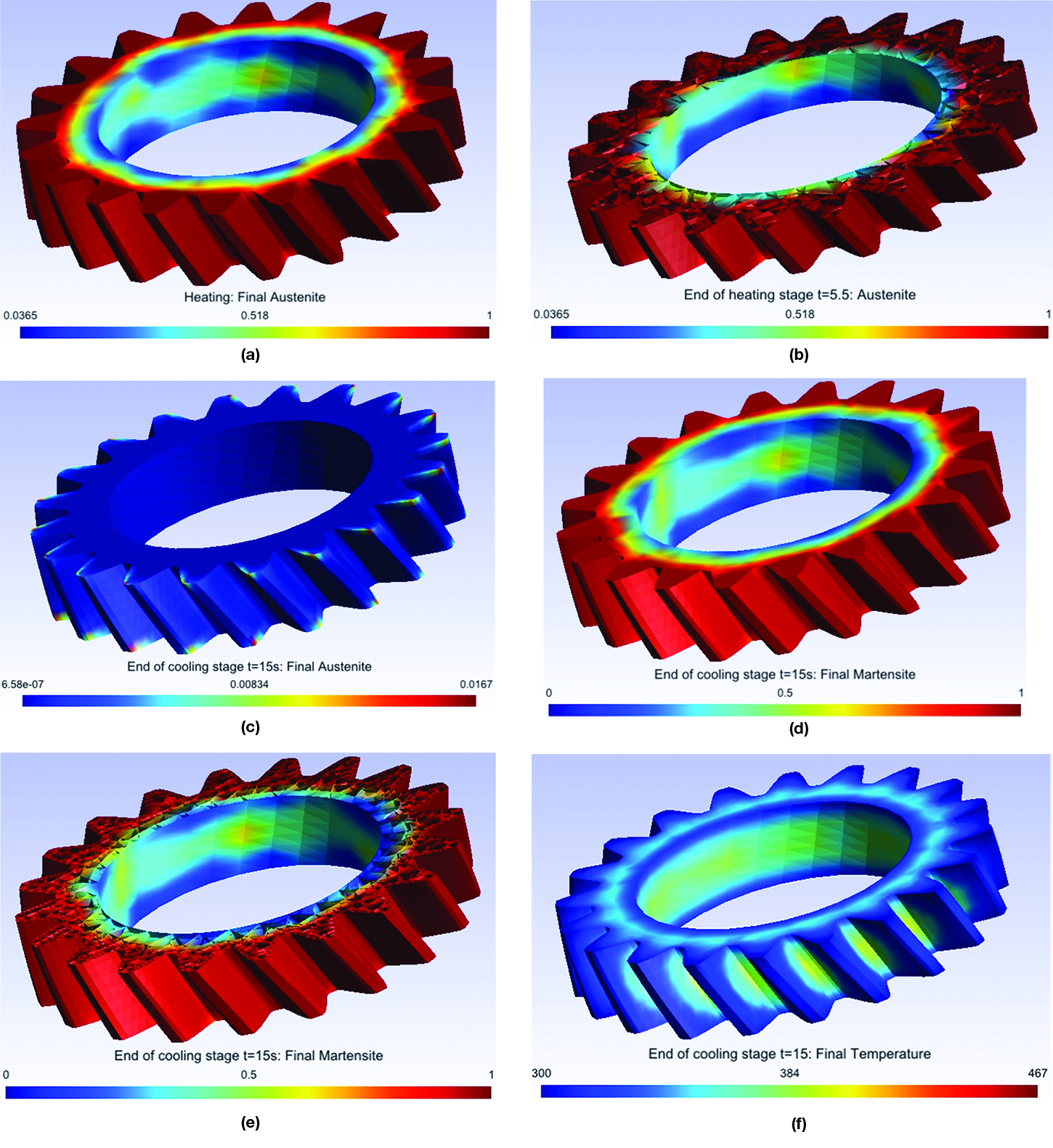
In this section we show some numerical simulations using the meshes and setting described in the previous section. The heating stage takes Ta = 5:5 seconds and the frequency is ! = 900 Hz. The cooling stage takes another 9.5 seconds, that is Tm = 15 seconds.
Figure 11:(a)-(f) show some numerical results at two different instants of time, namely at the end of the heating stage, t = 5:5, and at the end of the cooling stage, t = 15 for the austenite, martensite and final temperature. As it is expected, induction hardening heats up the gear from the tooth tip downward, so that the whole tooth is austenized (Figure 11:(a),(b)) and transform into martensite after cooling (Figure 11:(d),(e)). Figure 11:(c) shows that almost all the austenite has been transformed, retaining the workpiece a very small amount of this phase fraction.
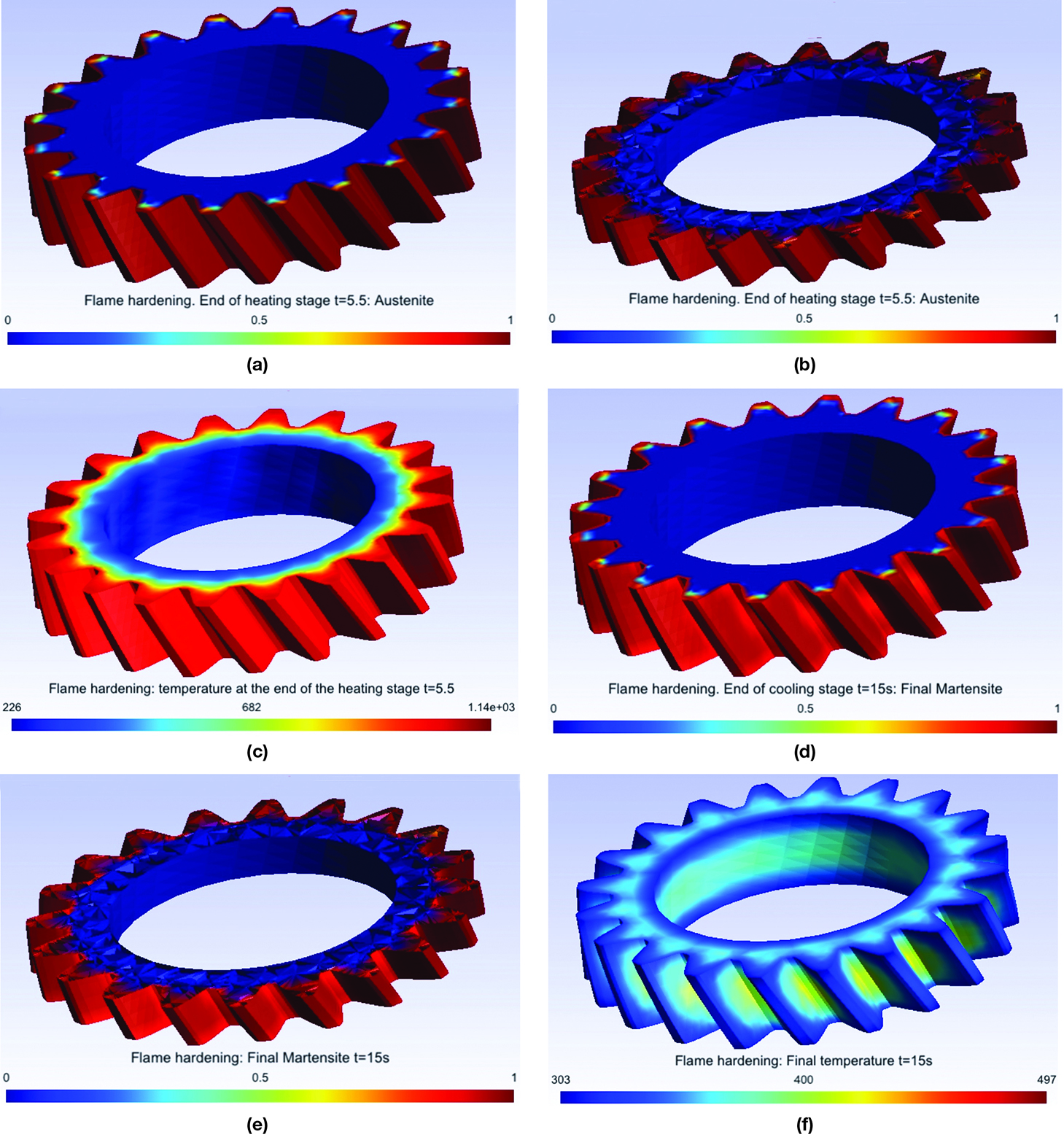
Another industrial technique used in the heat treatment of gears is flame hardening. This procedure can be used for both small and large gears. Usually, two techniques can be utilized: spinning and progressive heating ([12, 13]).
Figure 12:(a)-(f) show some numerical results corresponding to a flame hardening simulation. A more uniform contour can be observed in this case for both the austenite and martensite profiles, which is in good agreement with experimental results.
Conclusions
Some simplified mathematical models arising in the industrial processes of steel heat treating have been used for the numerical simulation of the hardening (induction or flame) of a helical gear. The numerical simulations have been performed with freeware packages available in the Internet, namely Freefem++, TetGen and gmsh. We have described how to do, step by step, a 3D mesh for a helical gear. This presentation should be considered at an academic level. We have tried to put in evidence the potentiality and performance of Freefem++ as a useful FEM tool to carry out fast and efficient numerical simulations in a complex 3D geometry. Of course, it is possible to consider more sophisticated models for the description of the industrial processes of steel heat treating. For instance, by including mechanical effects, deformations, stresses, etc., other phase fractions such as bainite and pearlite. This does not represent a constraint to Freefem++ since it can handle more complicate situations. Though the 3D meshes used here are coarse, in general the numerical results are in good agreement with known experimental results. We hope that the reader gives a try to these packages and convinces himself of its easy-to-use, versatility, robustness and efficiency.
Acknowledgements
This research was partially supported by Ministerio de Economía y Competitividad under grant MTM2010-16401 with the participation of FEDER, and Consejería de Educación y Ciencia de la Junta de Andalucía, research group FQM-315.
The authors wish to thank Dipl.-Ing. Dawid Nadolski, from the Foundation Institute of Materials Science (IWT Bremen), for granted us permission to use the illustration of the induction hardening machine shown in Figure 2. The authors are in debt with Prof. Dr. Dietmar Hömberg, from the Weiertraß Institut für Angewandte Analysis und Stochastik, WIAS-Berlin (Weierstraß Institute for Applied Analysis and Stochastics). His expertise and skills have led us to learn much about the mathematical modeling of steel heat treating.
We also thank our dearest colleague José Rafael Rodríguez Galván, from Universidad de Cádiz, who provided us with the file ff++listings.sty used in formatting the Freefem++ scripts of this paper.
Prof. Ortegón Gallego addresses his gratitude to Dr. Thomas Petzold, from WIAS-Berlin, who first taught him about multifrequency induction hardening for gear components and for letting him set contact with his colleague from Bremen Dipl.-Ing. Dawid Nadolski. He also thanks the organizers of the VII Modeling Week, Prof. Valeri Markov, from UCM, and Prof. J. I. Díaz, from IIM and UCM, for letting him participate in the 2013 edition as an instructor about the subject dealt in this paper.
References
- S. Auliac, A. Le Hyaric, J. Morice, F. Hecht, K. Ohtsuka, O. Pironneau, FreeFem++. Third Edition, Version 3.31-2, 2014. http://www.freefem.org/ff++/ftp/freefem++doc.pdf
- N. Barka, A. Chebak, A. El Ouafi, “Simulation of Helical Gear Heated by Induction Process Using 3D Model,” Advanced Materials Research, 658, 266–270, 2013.
- N. Bugliarello, BG˙ eorge, D. Giessel, D. McCurdy, R. Perkins, S. Richardson, C. Zimmerman, Heat treat processes for gears, Gear Solutions 38–51, July 2010.
- P. J. Frey, MEdit: “An interactive mesh visualization software,” Rapport technique INRIA Nº. 0253, 2001. http://www.ann.jussieu.fr/~frey/publications/RT-0253.pdf
- J. Fuhrmann, D. Hömberg and M. Uhle, “Numerical simulation of induction hardening of steel,” COMPEL, 18, No. 3, 482–493, 1999.
- C. Geuzaine J. F. Remacle, Gmsh Reference Manual, 2014. http://geuz.org/gmsh/doc/texinfo/gmsh.pdf
- Hang Si, TetGen: “A Quality Tetrahedral Mesh Generator and a 3D Delaunay Triangulator,” http://tetgen.berlios.de/, 2009.
- D. Hömberg, “A mathematical model for induction hardening including mechanical effects,” Nonlinear Analysis: Real World Applications, 5, 55–90, 2004.
- D. Hömberg, Thomas Petzold, Elisabetta Rocca, “Simulation of multifrequency- induction-hardening including phase transitions and mechanical effects,” WIAS Preprint No. 1975, 2014.
- D. Hömberg, Q. Liu, J. Montalvo-Urquizo, D. Nadolski, T. Petzold, A. Schulz, “Analysis and simulation of multifrequency induction hardening”, WIAS Preprint No. 1910, 2014.
- J. Montalvo Urquizo, Q. Liu, A. Schmidt, “Simulation of quenching involved in induction hardening including mechanical effects,” Computational Materials Science, 79, 639-649, 2013.
- F. J. Otto, D. H. Herring, “Gear Heat Treatment. Part I,” Heat Treating Progress, June, 2002.
- V. Rudnev, D. Loveless, R. Cook, M. Black, “Induction Hardening of Gears: a Review,” Heat Treatment of Metals, 4, 97–103, 2003.


 general practice for CQI-9 and AMS2750E")


