


Introduction
Press quenching is a specialized quenching technique that may be utilized to minimize the distortion of complex geometrical components during heat treatment1. Distortion is routinely encountered in industrial heat treating operations, and is an especially important consideration where high accuracy, precision components are concerned. It can result from a wide variety of independent contributing factors. In press quenching these can include, among others:
- The quality and prior processing history of the material from which the part in question has been manufactured
- The prior thermal history and residual stress distribution contained within the part
- The generation of unbalanced thermal and transformation stresses induced by the quenching operation
- The grade of material and austenitizing temperature that is used
- Transfer time between the austenitizing furnace and the quenching machine
- The type, condition, quantity, and temperature of quenchant used
- Direction and selective metering of quenchant flow over the component
- Duration of the quench at various flow rates
- Locations of contact points on the component for applying external loads
- Magnitude of the forces applied for maintaining the required part geometry
- Proper quench die tooling design, set-up, and maintenance
- Pulsing methodology
Distortion issues during quenching
High precision components such as automotive spiral bevel gears and aerospace quality bearing races can often distort appreciably during open tank oil quenching. Press quenching can help to minimize the distortion of such components by utilizing specialized tooling for generating concentrated forces at key locations to constrain the movement of the component in a carefully controlled manner. It can be performed on a wide variety of components manufactured from both ferrous and non-ferrous based alloys. For example, a number of aluminum alloys are routinely press quenched. Common steel alloys that are press quenched include high carbon through-hardening grades such as AISI 52100 and A2 tool steel. Press quenching is particularly well suited for the processing of carburizing steel grades such as AISI 9310, 8620, and 3310.
Ideally, the transformation temperature should be the same throughout the entire cross-section of the component during quenching so that the material is capable of transforming in a uniform manner. However, in case carburized parts the martensite start transformation temperature (Ms) is not uniform throughout the entire cross-section of the part. During carburizing, a composition gradient is produced as carbon is diffused into the part surface. This results in a corresponding gradient in the transformation temperature near the surface that can promote or aggravate distortion issues in such components during quenching. Non-uniformities in the base material microstructure due to segregation or improperly normalized material can also contribute to this type of distortion. Thin walled components such as large diameter bearing races, are generally more susceptible to these distortion related issues than are relatively massive, compact geometries. Although press quenching cannot eliminate these effects, its use can help to minimize their contribution to the overall distortion that is produced during heat treatment.
The amount of distortion encountered depends strongly on the nature of the heat treating process that is used. In order to minimize distortion related issues during quenching, heat should be extracted from the component in as uniform a manner as possible. This can be difficult to achieve for parts that are designed with sudden changes in geometry with heavy or thick sections located adjacent to relatively thin sections on the same component. A good example of this is the teeth on a spiral bevel gear or pinion. The teeth have a greater surface area to volume ratio than the body of the gear or pinion, and due to their symmetrical nature and distribution the teeth have a tendency to distort by unwinding during quenching. As the work piece is submerged into the quenching medium, the teeth tend to cool and contract much more rapidly than the adjacent heavier sections. As a result of this varying quench rate, the teeth harden more rapidly and contract while the balance of the component is still in an expanded state. The outcome of quenching such components is the generation of temperature gradients and non-uniform transformation induced stresses. This particular issue can be addressed in press quenching by selectively directing the quenchant flow toward the thicker sections and baffling it away from the teeth in order to promote a more uniform quench. By implementing this important technique, lower levels of transformation-induced distortion can be achieved.
Press quenching machines
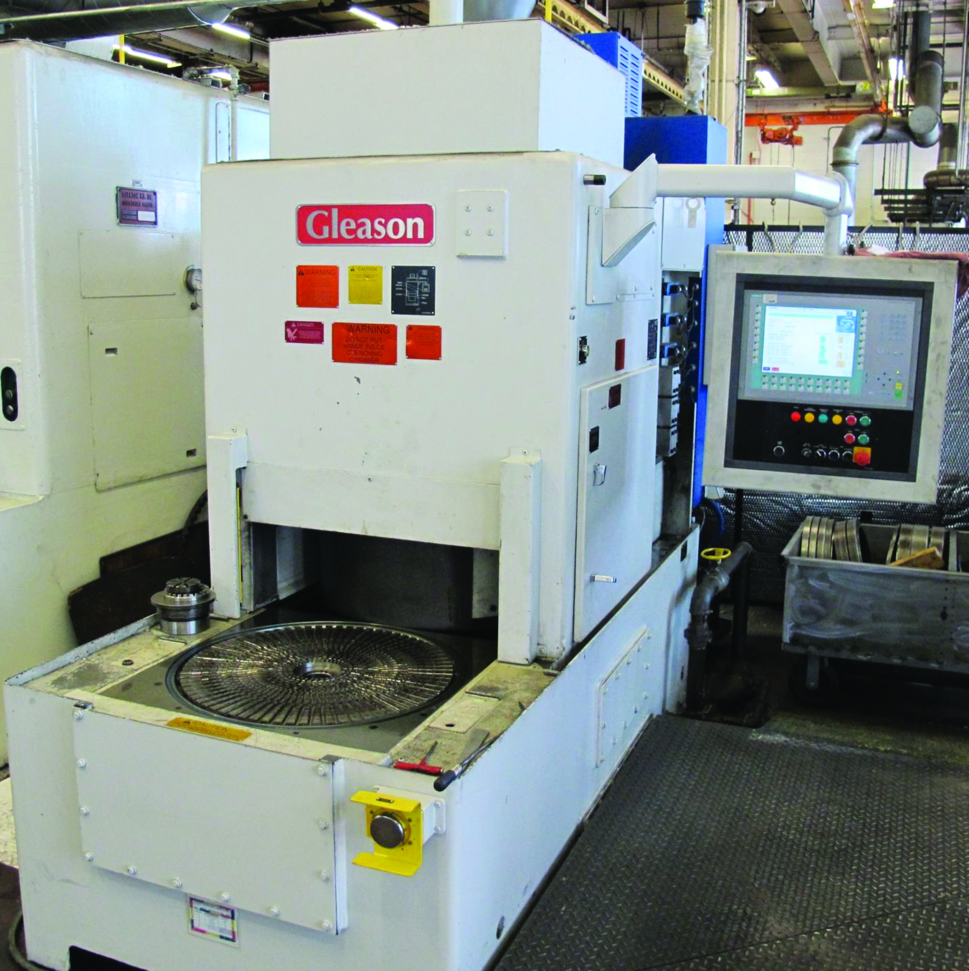
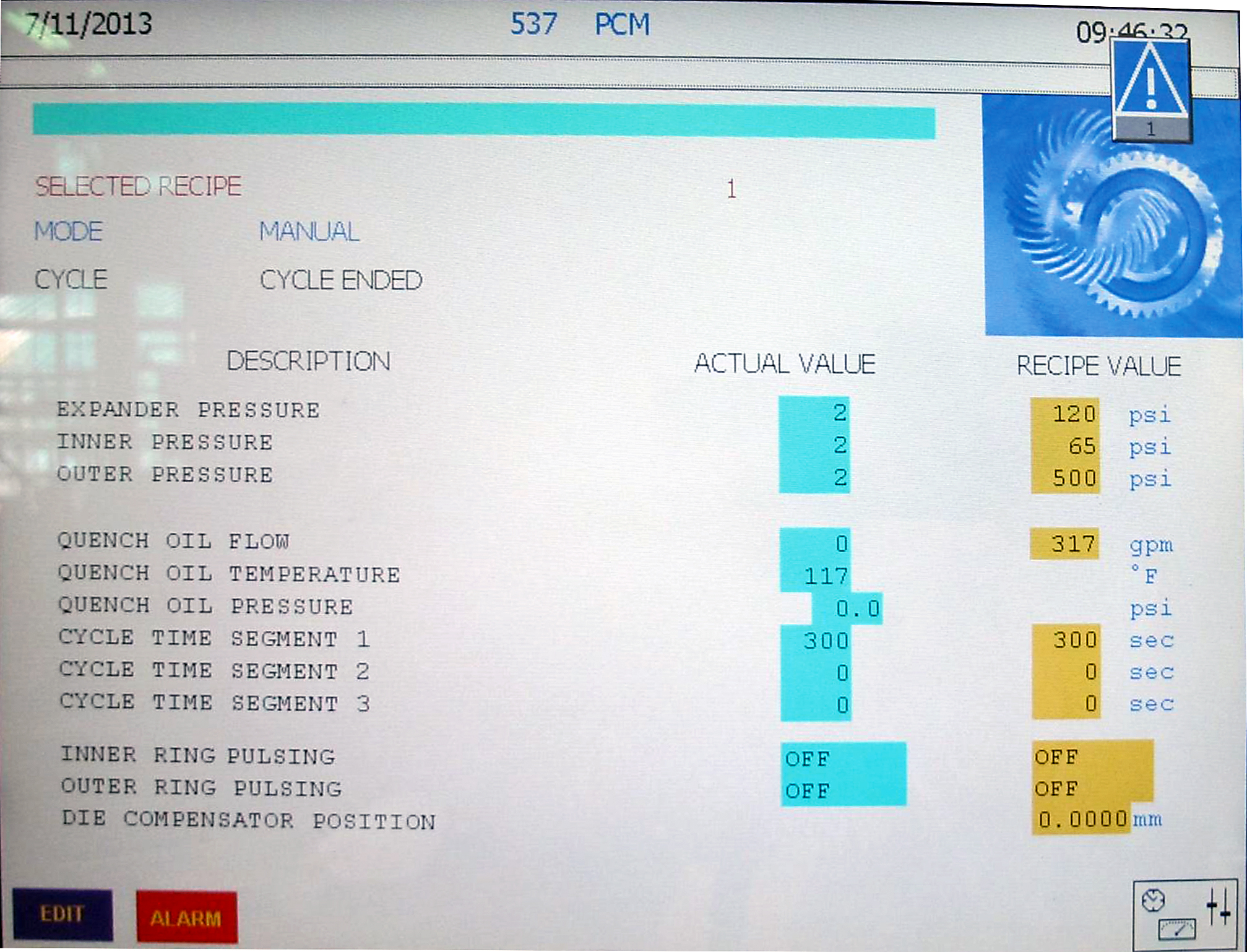
A representative version of a standard quenching machine is depicted in Figure 1, and examples of the numerous parameters that may be adjusted during the course of a typical quenching cycle are shown on the machine’s main control screen in Figure 2. During operation, the component to be quenched is removed from a separate furnace (usually a box, continuous rotary, or pusher type furnace) and is placed onto the tooling of the lower die assembly. A close up view of this die assembly is shown in Figure 3.
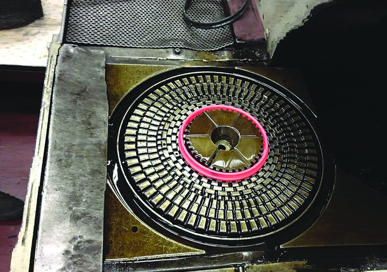
After the part is successfully loaded onto the lower die assembly, the machine is actuated and the part is retracted into the machine where it is centered below the upper hydraulic ram assembly. As the assembly descends the center ram actuates one or more internal expanders that make contact with the inner diameter of the component at the specified points to maintain roundness at these locations (see Figure 4). Each component of the ram assembly (the center expander, inner and outer dies) is controlled independently through three separate proportional valves. A predetermined pressure level is usually maintained by the expander throughout the quench cycle. The inner and outer dies are lowered to make physical contact with the upper surfaces of the component being quenched in order to control alignment, dish, and part flatness during the course of the quenching cycle. The flow of quench oil is then activated to quench the part.
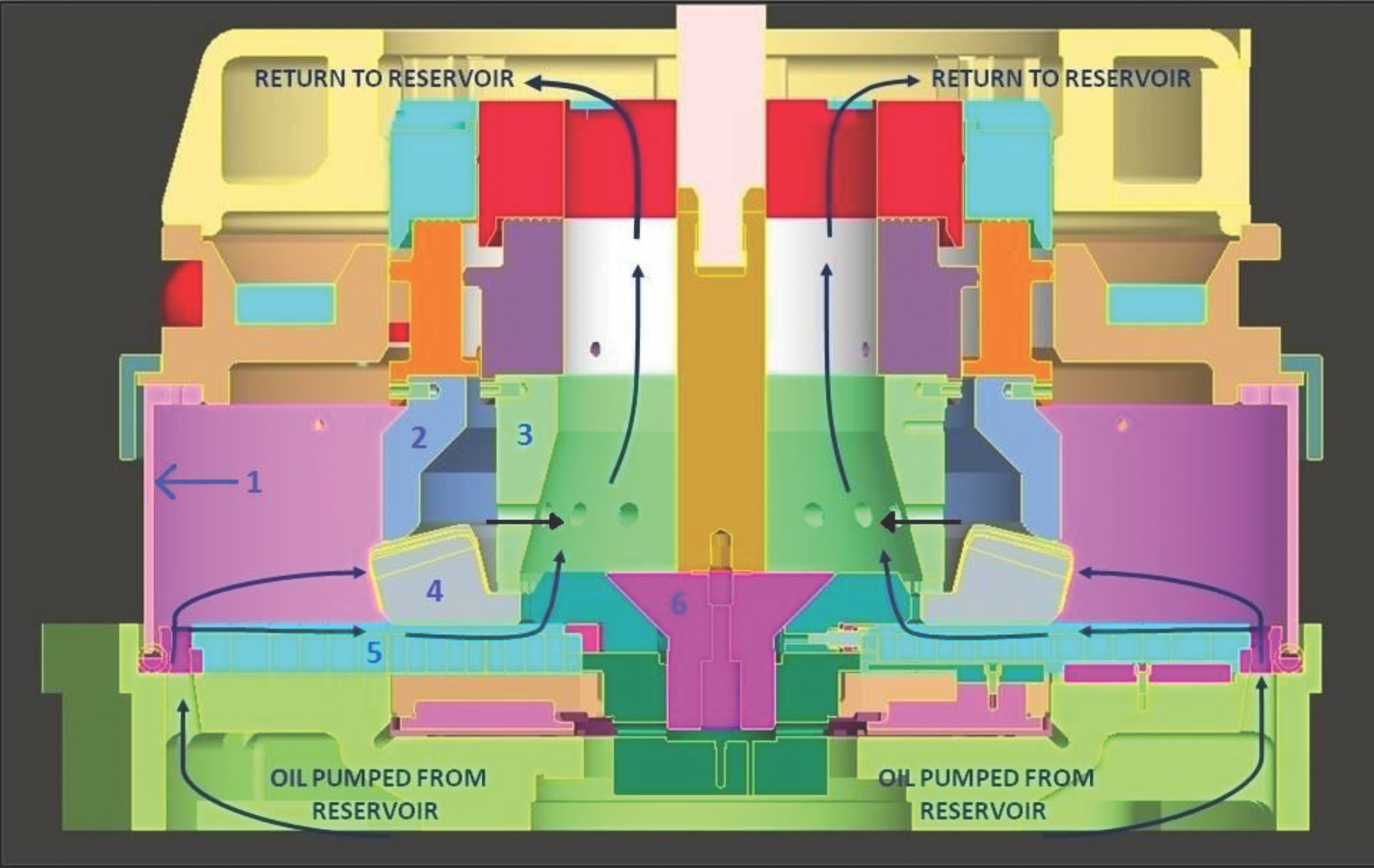
Figure 4 illustrates an example of a quench oil circulation path that can be established within the quenching chamber. Oil is pumped into the quench chamber through apertures around the outside diameter of the lower die. As the chamber fills up surrounding the component, oil flows out of the top. If the tooling is properly designed, the direction of oil flow over the component can be adjusted to obtain the best overall results. The elongated apertures at the exit may be adjusted to restrict oil flow, or may be fully opened to maximize flow depending upon the requirements for the part in question. The lower dies are constructed from several different concentric slotted rings that may be rotated to provide full flow or to restrict oil flow to the underside of the part. These particular features can be finely adjusted to help minimize the degree of distortion attributed to uneven heat removal during quenching. Timed segments during the quenching cycle can also be utilized to vary both the oil flow rate and duration in order to establish a well defined quenching recipe for a specific part design.
The oil quenching process itself may consist of up to three general stages: (1) the initial vapor blanket stage where the first oil to come in contact with the part is instantly vaporized and forms a vapor barrier that surrounds the part and acts as an effective thermal insulting layer; (2) the vapor transport stage where oil breaks through the vapor blanket resulting in more rapid heat transfer; and (3) the liquid stage where heat extraction occurs predominately by convective heat transfer. In order for uniform heat extraction to occur during the initial stages of quenching, the oil flow rates must be sufficient to prevent the formation of a vapor blanket. If vapor bubbles are allowed to form in areas around the surface of the component, uneven heat extraction will result that can lead to unacceptable hardness variations and distortion. After this initial quenching stage has been successfully eliminated, lower quenchant flow rates may be safely tolerated. The quenchant flow rate profile that is ultimately established for the part in question must be carefully selected so that the hardness and geometry requirements are satisfactorily met. Too slow of a quench rate will result in a slack quench, undesirable transformation products, and hardness variations. Too rapid of a quench rate could result in cracking and/or unacceptable part distortion. The establishment of an oil flow path around the part and selection of the proper oil flow rate are often determined using a trial and error process. Success frequently depends upon the knowledge, experience, and skill of the machine operator.
The average oil temperature for most press quenching operations typically falls somewhere within the range of approximately 75ºF to165ºF, depending upon the material in question, the nature of the quenching operation, the type of quench oil being used, and post heat treat property requirements. Average quench oil temperatures exceeding 140ºF should generally be avoided as a precaution to prevent damage to the machine seals that are used to contain the quench oil. Proper and routine maintenance of the quench oil bath is an often neglected aspect of the press quenching process and can lead to unexpected variations in the hardening response of the materials processed in these types of systems. As the quench oil continues to be used, the oil additives gradually break down, and fine particulates can accumulate over time even if the oil is continuously filtered. If left undetected, this can lead to accelerated quench rates which can compromise the integrity of the oil quenching process.
A specific die tooling design configuration and machine set-up is required for each component that is press quenched. The use of expanding segmental dies are often employed to maintain bore size and roundness in bearing races and gears. If a component possesses a bore diameter that is physically too small to accommodate these segmental dies, a solid plug could be used instead to control the diameter and taper of the bore. The plug would simply be removed after quenching. When there are different locating surfaces on the lower die assembly it is imperative that the dimensions between these surfaces be held to a close tolerance from piece to piece. Failure to adhere to this rule may result in unwanted distortion and/or inconsistent results. Contracting dies are also available to maintain the geometrical tolerances for the outside diameter of components where this is a critical factor. A good example of this are gears that incorporate thin web sections in conjunction with relatively heavy sections for gear teeth, bosses, and bearing diameters. Gears used in aerospace applications such as helicopter gear assemblies often incorporate several of these features which may cause them to contract unevenly during quenching. This problem can be effectively remedied by the application of compressive loads on the outside surface of the component during press quenching.
It should also be noted that the inner and outer dies are typically pulsed during quenching to maintain the geometry of the part and to minimize distortion. The pulse feature periodically eases the applied pressure exerted by the inner and outer dies, allowing the component to contract normally as it cools while still maintaining the desired part geometry. If this feature was not incorporated (and on some of the older machines it isn’t available), the stresses that would be induced from frictional contact between the die assembly and the component would not allow it to contract normally as it cools. Pulsing effectively reduces this frictional contact, and avoids distortion related issues due to eccentricity and out-of-flatness. The pulsing technique keeps the dies in contact with the part throughout the entire quenching cycle, but allows the pressure to be released and then re-applied approximately every two seconds. The inner and outer dies are typically cycled in this manner. However, the expander pressure is not normally pulsed.
Case study
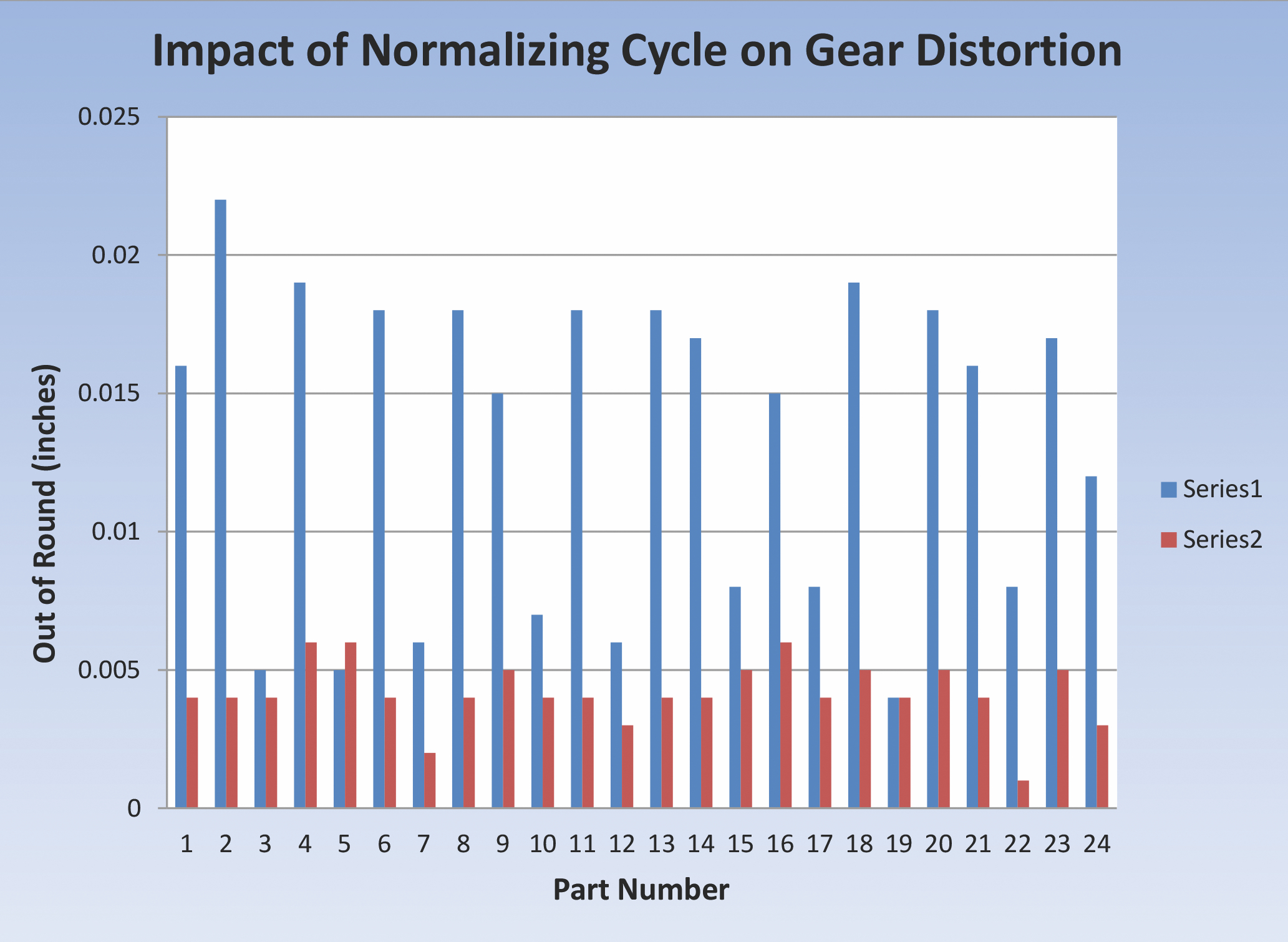
The dimensional tolerances achieved during quenching are strongly dependent upon the various factors that can contribute to part distortion, as mentioned previously. The prior thermal history and residual stress distribution contained within the part can contribute significantly to distortion related issues during heat treatment, and this is certainly true during press quenching, as well. A case study that clearly illustrates this point was conducted on a number of automotive gears that were manufactured from AISI 8620H, a chromium-nickel-molybdenum case carburizing steel that is commonly designated for use in gearing applications. The outside diameter of these machined gears measured approximately 13 3/4 inches prior to austenitizing and press quenching. They were processed on two separate furnace loads. For the first set of gears, which were designated Series 1, the normalizing temperature that was used was 1700ºF. These gears received a single normalizing cycle. The second set of gears, labeled Series 2, was normalized twice in succession. The first normalizing cycle they received was identical to that used for the Series 1 gears. For the second normalizing cycle, the temperature was raised to 1750oF. Each group of 24 gears was subsequently processed through a gas carburizing furnace using an endothermic atmosphere at a temperature of 1700ºF to generate effective case depths in the range of 0.040 to 0.055 inches. The gears were all cooled to room temperature after carburizing was completed. They were then reheated to the austenitizing temperature of 1570ºF, and individually press quenched.
The resulting distortion that was measured on the outside diameter of these gears in terms of out of round is shown in Figure 5. Examination of this chart reveals that the gears normalized once at 1700oF (Series 1) exhibited substantially greater amounts of distortion in terms of out of round than the gears which were normalized twice using a final temperature of 1750ºF (Series 2).
Summary
Press quenching is a specialized quenching technique that may be utilized to minimize the distortion of complex geometrical components during heat treatment. It is a versatile and time proven technique that can accommodate a wide variety of material grades and component geometries. The success of this technique depends strongly on a large number of variables. Some of the more important among these variables include the knowledge, skill, and experience of the machine operator. In this investigation, the prior thermal history of the material was also demonstrated to be an important, and often overlooked, variable, as well.
References
- Arthur C. Reardon, “Press Quenching”, in ASM Handbook, Volume 4a, Steel Heat Treating Fundamentals and Processes, J. Dossett and G. Totten, Editors, ASM International, Nov. 2013


 general practice for CQI-9 and AMS2750E")


