


Vanadis 6 ledeburitic tool steel was subjected to sub-zero treatment at minus-75°C for different durations and for different subsequent tempering regimes. The impact of these treatments on the microstructure, hardness variations, and toughness characteristics of the steel was investigated. The obtained results infer that the retained austenite amount was reduced to one fourth by sub-zero treatment (SZT), and the population density of add-on carbides was increased by a factor of three to seven, depending on the duration of SZT. Tempering always reduced the population density of these particles. A hardness increased by 30 to 60 HV10 was recorded after sub-zero treatment, but tempering to the secondary hardness peak induced much more significant hardness decrease than what was established in conventionally quenched steel. The flexural strength was not negatively influenced by sub-zero treatment at minus-75°C while the fracture toughness tests gave worse values of this quantity, except the case of steel tempered to the secondary hardness peak.
1 Introduction
In conventional heat treatment of tools made of high-alloyed Cr and Cr–V ledeburitic steels, the material is gradually heated to the austenitizing temperature (recommended by the steel manufacturers), held there for prescribed time, and cooled down rapidly to room temperature. Afterwards, the steels should be subjected to tempering immediately to prevent the retained austenite stabilization and to induce transformations leading to the achievement of final properties of tools or components.
Ledeburitic steels are commonly used as tool materials for cold-work applications. In order to generate high abrasive wear resistance, they contain a high amount of carbide phases embedded in a metallic matrix. On the other hand, these carbides, together with high overall steel hardness, deteriorate the material resistance against crack initiation/propagation, expressed by the fracture toughness KIC. Also, the flexural strength of ledeburitic steels, which is often also taken as a measure of resistance against crack initiation for brittle materials, manifests relatively low values. Moreover, conventionally produced ledeburitic steels are cast and afterwards hot formed. As a consequence, they contain band-like carbides, thus they suffer from anisotropy of key mechanical properties [1].
Sub-zero treatment is defined as a supplementary process to conventional heat treatment. Unlike conventional heat treatment (CHT), it is a process where the tools or components are immersed into a suitable cryo-processing medium, stored there for a pre-determined time (usually in 10s of hours), and re-heated to room temperature. Research works conducted on the application of this kind of treatment have shown that sub-zero treatments provide extra benefits to the tooling industry such as increased hardness [2,3], better wear performance [3,4], and improved dimensional stability of products [5].
According to recent studies, the following crucial microstructural changes are responsible for these benefits:
1. Considerably reduced retained austenite (γR) amount [2,6-9].
2. Refinement of the martensite along with an enhanced number of crystal defects such as dislocations and twins inside martensitic domains [7,9,10].
3. Enhancement of number and population density of small globular carbides (SGCs) [2,3,7,8,11,12].
4. Acceleration of the precipitation rate of nano-sized transient carbides [11-15].
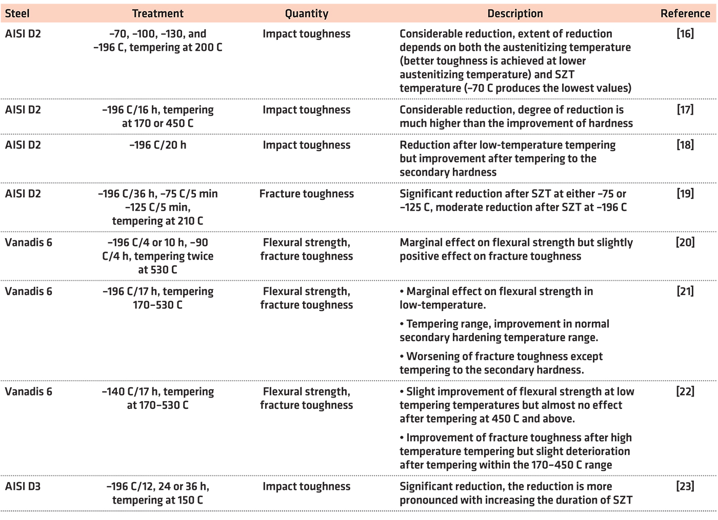
However, the impact of sub-zero treatments on the toughness characteristics (fracture toughness, flexural strength, and impact toughness) is controversial as Table 1 illustrates.
The question of an optimal regime of sub-zero treatments is still under debate. In the “pioneer age” of this technique, it was believed within the professional community that the benefits of sub-zero treatments are based only on the reduction of retained austenite amount. Therefore, the temperatures of about minus-75°C were widely used in laboratory and industrial practice. Lower temperatures were not accepted for the treatments since their use often led to premature failure of tools due to thermal shocks associated with the use of very low temperatures. Treatment at the boiling temperature of liquid nitrogen (minus-196°C) was introduced into industrial practice much later, when the devices enabled could carry out well controlled cooling down to such low temperature.
Other sub-zero treatment temperatures were suggested only by a very limited number of researchers. Reitz and Pendray and Gavriljuk et al., for instance, suggested the temperature of minus-140°C [24,25]. Recent studies dealing with thorough analysis of microstructure and toughness of the Vanadis 6 steel treated in this way gave very promising results [22,26]. Alternatively, there were attempts and/or suggestions with the use of the temperature of boiling helium (minus-269°C) [13,27]. However, the treatment temperature of minus-75°C also deserves attention since one can expect the phenomena being responsible for earlier mentioned ameliorations in properties would proceed faster at minus-75°C than at lower temperatures. Also, practical experiences indicated the extent of “extra” wear performance (or other property), which can be gained by the use of SZT at minus-96°C (as compared with treatments at minus-75°C) depends on the material chemistry. For instance, the wear performance of AISI D2 steel was improved by a factor of 2.59 by the treatment in liquid nitrogen (as compared with treatment at minus-75°C), while only an improvement by a factor of 1.39 was recorded for CPM 10-V steel (steel with high vanadium content) [24].
This paper is thus focused to an in-depth description of the results obtained with the sub-zero treatments of Vanadis 6 steel at the temperature of minus-75°C, and to their careful discussion. Microstructural changes are presented, and they are related to the hardness, flexural strength, and fracture toughness of examined steel. The obtained results are also compared to what was obtained by treatments at temperatures minus-140, minus-196, and minus-269°C, respectively.
2 Experimental
The powder metallurgy (PM) tool steel, Vanadis 6, with nominal composition (in wt%) 2.1 C, 1 Si, 0.4 Mn, 6.8 Cr, 1.5 Mo, 5.4 V, and Fe as a balance was selected for the examinations. Due to the PM technique used for steel manufacturing, the material is free of macro-segregations and also of carbide bands and manifests high degree of isotropy. This makes it possible to disregard the orientation in sample manufacturing. The initial microstructure was soft-annealed with a hardness of 272 HV10.
The specimens were machined to a net-shape and subjected to the heat-treatment schedules. Conventional heat treatment consisted of gradual heating up to the austenitizing temperature of 1,050°C, holding at that temperature for 30 minutes to enable the dissolution of carbides and austenite homogenization, which was followed by room temperature quenching by using cold nitrogen gas. Then, one set of specimens was separated and subjected instantly to tempering treatments. The other specimens were moved to a cryogenic system and subjected to sub-zero treatments at the temperature of minus-75°C and for different durations prior to tempering.
In sub-zero treatments, room-temperature quenched specimens were cooled down to minus-75°C, at a controlled cooling rate of 1°C/min, stored at the lowest temperature for predetermined duration (4, 10, 17, 24, or 48 hours), and re-heated by a heating rate of
1°C/min to room temperature. Immediately after the specimens reached room temperature, they were moved to the tempering furnace where they were tempered in an atmosphere of pure technical nitrogen. Tempering consisted of two cycles (2 + 2 hours), at temperatures in the range 170-530°C. However, the tempering temperature of 600°C was added to the experiments with flexural strength in order to verify the behavior of this mechanical quantity at tempering temperature located beyond the secondary hardness peak.
A NETZSCH DIL 402 C dilatometer (Netzsch, Selb, Germany) was used within the temperature range of 20 down to minus-150°C in order to estimate the martensite finish temperature of the Vanadis 6 steel austenitized at given austenitizing conditions.
The specimens for microstructural examinations were prepared using standard metallographic grinding by a set of abrasive papers (with a grit of 180, 320, 600, and 1,200) and polishing (by using the 9, 3, and 1 μm diamond suspensions). Then, the specimens were etched with Villella-Bain reagent (5 ml hydrochloric acid, 1 g picric acid in 100 ml of ethanol) for 10 seconds. For the material microstructure examinations, a JEOL JSM 7600 F scanning electron microscope (SEM, Jeol Ltd., Tokyo, Japan), operating at a 15 kV acceleration voltage was used. Microstructural examinations were coupled with energy dispersive spectrometry (EDS) by using an EDS detector (Oxford Instruments, plc., High Wycombe, UK). SEM micrographs were acquired in a combined 50:50 detection of secondary electrons and backscattered electrons (BE). The reason was that the material contains eutectic carbides (ECs), secondary carbides (SCs), and small globular carbides after application of the earlier mentioned heat-treatment schedules. It has been proven recently that the ECs are represented by vanadium-rich (more than 50 wt%V) MC particles, while the SCs are the M7C3 particles (with a high percentage of chromium), and that SGCs were determined to be alloyed cementite [7]. This made it possible to clearly differentiate between the ECs on the one side and the SCs (and the SGCs) on the other side by strong differences in BE yield. Unfortunately, this categorization fails in differentiation between SCs and SGCs as their BE yield is very similar. Therefore, the classification based on the particle size was adopted to distinguish the ECs and the SGCs; the carbides finer than 0.5 μm were considered as the SGCs while the coarser ones as SCs.
Determination of population density of carbide particles (categorized as above-described) was carried out on 25 randomly acquired SEM micrographs for each specimen. Standard magnification for acquisition of SEM images was 3,000×. For better identification of SGCs, additional SEM micrographs at a magnification of 7,500× were recorded because some of these particles had a size well below 100 nm. The acquisition of SEM images was coupled with EDS mapping of chromium and vanadium in order to clearly differentiate between the carbides, as mentioned earlier. The mean values and the standard deviations of the obtained data were calculated.
The phase constitution of differently heat-treated specimens was determined by using X-ray diffraction (XRD, Philips Analytical B.V., Almelo, The Netherlands) technique. A Phillips PW 1710 diffractometer with filtered CoKα characteristic radiation was used for this purpose. The diffracted radiation was registered within a two-theta angle range of 30-127 degrees. The retained austenite amounts were determined following the appropriate ASTM E975-13 standard [28], taking the characteristic peaks of both the martensite (α´) and the austenite (γ), namely (200)α´, (200)γ, (211)α´, and (220)γ into the consideration. As reported recently [2,7], however, these peaks are often superimposed by the characteristic peaks of carbides, which might influence the accuracy of the obtained results negatively. Therefore, the analyses were coupled with Rietveld refinement of the obtained X-ray spectra before computing the retained austenite amounts.
Hardness of differently heat-treated specimens was measured by using a Vickers indentation technique at a load of 98.1 N (HV 10) following the appropriate Czech standard [29]. A ZWICK 3212 hardness tester (Zwick-Roell, Ulm, Germany) was used. The distance between two adjacent indents was kept minimum 5 mm, and the dwell time used for each indent was 15 seconds; 10 measurements were done for each specimen. Then, both the mean values and standard deviations of measured values were calculated.
10 by 10 by 100 mm bar specimens were used for flexural strength determination. Prior to measurements, the specimens were polished to a final surface roughness, Ra, between 0.05 and 0.07 μm. This step is very important to obtain reliable results because it is known that the surface finish plays an important role in this type of measurement, and differences in surface finish (in microns of Ra) can influence the obtained flexural strength values within the range of hundreds MPa [30]. An Instron 8862 test device (Instron, Norwood, MA, USA) was used. Specimens were tested in a three-point bending configuration at a loading rate of 1 mm/min, until the moment of fracture. The distance between loading roller supports was 80 mm. The flexural strength R was calculated according Equation 1 (following the appropriate Czech standard [31])
 where F represents fracture force (maximum load on the load–deflection trace), L is distance of roller supports in three-point bending, b is the specimen thickness, and h is the specimen height (dimension in the direction of the acting load). In addition, the total work of fracture, Wof, and the plastic part of the work of fracture, Wpl, were evaluated from the corresponding area below the measured load-deflection (load displacement) curve.
Reliable evaluation of fracture toughness of materials by plane strain fracture toughness requires prior fatigue pre-cracking of the specimens in order to achieve a sharp and reproducible crack tip geometry for testing. Therefore, pre-cracked specimens with 10 by 10 by 55 mm dimensions were used for fracture toughness determination in the current work. Pre-cracking the samples was carried out after the heat treatment. A resonance frequency machine Cracktronic 8024 (Russenberger Prüfmaschinen AG, Neuhausen am Rheinfall, Switzerland) was used for this purpose, and the specimens were loaded in four-point bending configuration. The crack development was monitored on both sides of the sample using a digital long-distance microscope. Both the pre-crack preparation and the testing were carried out at room temperature following the ISO 12137 standard [32]. In testing, the specimens were loaded in three-point bending with a roller span of 40 mm and at a loading rate of 0.1 mm/min. An Instron 8862 machine (Instron, Norwood, MA, USA) was used. Specimen deflection was measured by means of an inductive transducer integrated directly into the loading axis. Five samples were tested for each investigated heat-treatment (SZT, tempering) condition.
Fracture surfaces were analyzed by using the scanning electron microscope JEOL JSM 7600 F. SEM micrographs were acquired in the secondary electron detection regime at different magnifications enabling a study of the micro-morphology of fracture surfaces. Particular attention has been paid to the role of carbide particles in the fracture propagation.
3 Results and Discussion
The change in the length of the Vanadis 6 specimen after quenching from 1,050°C down to 20°C and immediate moving to the dilatometer, where the material was cooled down from 20°C to minus-110°C is presented in Figure 1.

The onset at the relative length curve is located at minus-45.8°C. The inflection at the linear expansion coefficient curve is at minus-43.1°C. From these two values it can be summarized that the critical Mf temperature of the Vanadis 6 steel lies at approximately minus-45°C, it is thus higher than the selected sub-zero treatment temperature.
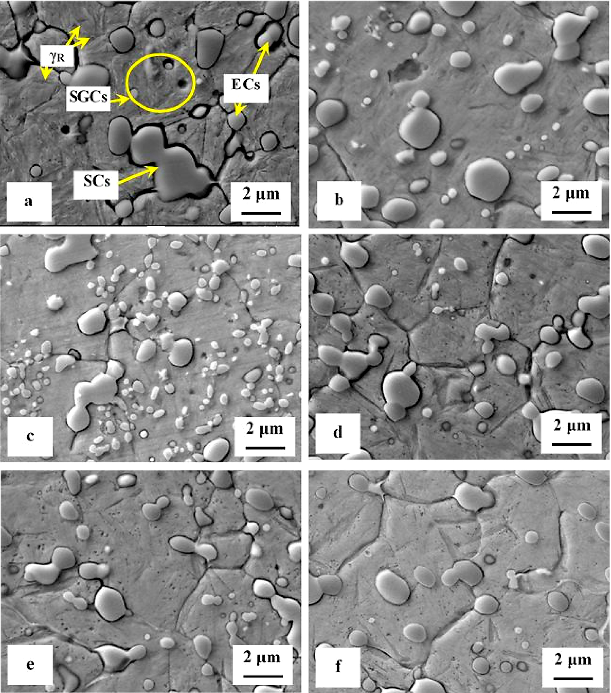
SEM micrographs in Figure 2 show the microstructure of Vanadis 6 steel in the conventionally heat-treated state (a), and after subsequent SZT at minus-75°C for different durations (b-f). The matrix and different carbide particles are the main microstructural constituents of the steel, irrespectively to the heat-treatment schedule used. The matrix is mainly martensitic, with a certain amount of retained austenite. The retained austenite is in-between the martensitic laths as SEM micrograph in Figure 2a illustrates. The carbide particles are the eutectic carbides, the secondary carbides, and small globular carbides. The number and population density of both the ECs and the SCs are nearly constant within the range of the heat-treatment schedules used. Alternatively, the number and population density of SGCs change with the duration of SZT; they increase substantially up to the 10-hour duration of SZT in Figure 2b and 2c where the maximum population density of 233 × 103 mm-2 was achieved (Table 2), and then decrease, Figure 2d-f.
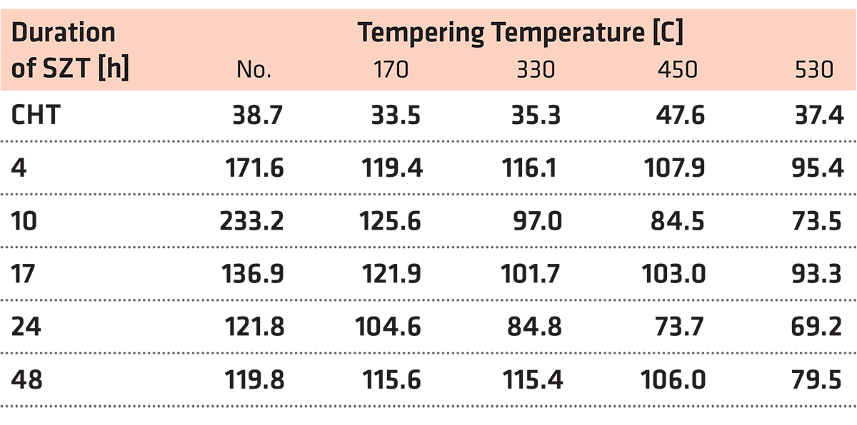
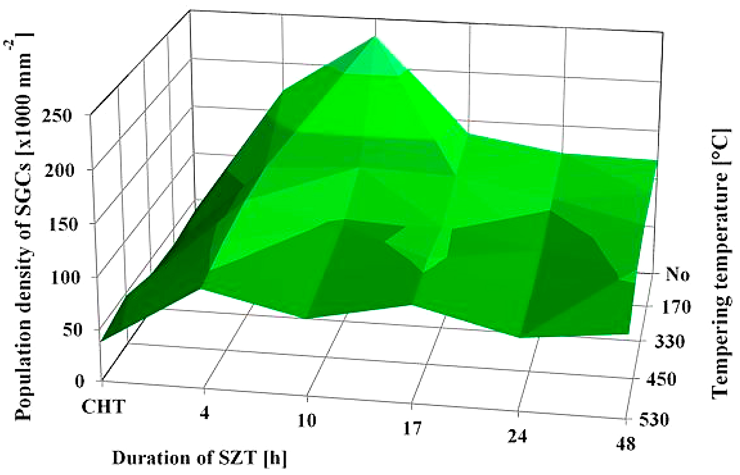
It is shown in Table 2 and in Figure 3 that tempering treatment always induces a reduction of population density of SGCs, despite that their population density remains two- to three-fold higher than what is produced by conventional heat treatment. Finally, it should be mentioned that SZT does not modify the amounts and population densities of ECs and SCs in Vanadis 6 steel as reported recently [7,12]. The reason is that these carbides are stable up to much higher temperatures and thus neither the SZTs nor the tempering modify their quantitative characteristics.
A series of high-magnification SEM micrographs in Figure 4 depicts the microstructural alterations of sub-zero treated (at minus-75°C) steel with increasing the tempering temperature. The as-sub-zero treated material microstructure contains the matrix formed by the martensite and retained austenite and eutectic, secondary, and small globular carbides, Figure 4a. Tempering treatment modifies the material microstructure as follows: The matrix manifests more pronounced sensitivity to the etching agent, Figure 4b-e. This is reflected by extensive roughening of the originally smooth metallographic surface, and thus by lowered distinctness of originally clearly visible matrix microstructural features (martensite laths, retained austenite, grain boundaries, etc.) obtained by austenitizing, quenching, and sub-zero treatments, compare with Figure 4a. Mentioned changes can be ascribed to extensive precipitation of nano-sized carbides. These carbide particles become visible after tempering at 450 or 530°C, as tiny elongated formations in Figure 4d and 4e. At the same time, the retained austenite disappears from the microstructure because it was decomposed into either “secondary” martensite or bainite during the cool down from the tempering temperature. Last but not the least, it should be noticed the population density of both the ECs and the SCs are nearly unaffected by tempering while the population density of SGCs decreases with tempering treatment, compare Figure 4a with micrographs in Figure 4b-e and see also Table 2. It should be noted that similar microstructural development was detected also for the steel after SZT at minus-75°C for other (shorter or longer) durations.

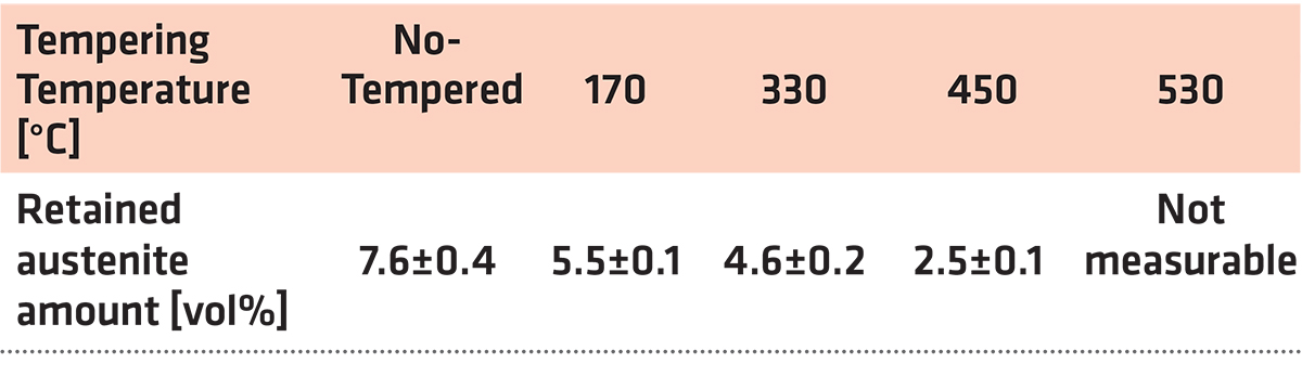
The dependence of the retained austenite amount on the tempering temperature for specimens after sub-zero treatment at minus-75°C for 17 hours is in Table 3. The amount of γR was 7.6 ± 0.4 vol% in the prior-to-tempering state. Tempering at low temperatures reduces the γR amount only moderately. In contrast, tempering at higher temperatures results in either the significant reduction (450°C) or in the almost complete removal of the retained austenite.
The γR amount in CHT specimens was about 20 vol% as reported recently [7,12]. The obtained results imply the SZT at minus-75°C reduces the γR amount to approximately one third as compared with the room temperature quenching. At the same time, however, it is worth noting that treatments at minus-140 or minus-196°C act more effectively in reduction of retained austenite; the γR amounts were determined 4.3 and 2.1 vol% for steel that was SZT at minus-140 and minus-196°C, respectively [7,12,26].
The prior-to-tempering hardness for conventionally (room temperature) quenched Vanadis 6 steel was 875 ± 16 HV10 in Figure 5. The hardness values of the steel after sub-zero treatment at minus-75°C for 4, 17, and 48 hours were 908 ± 30, 930 ± 10, and 925 ± 6 HV10, respectively. Thus, the obtained results imply the hardness of the Vanadis 6 steel is higher due to the sub-zero treatments at minus-75°C, and that the hardness improvement reaches the maximum for the material treated for the duration of 17 hours. On the other hand, the hardness improvement is less significant than what was obtained by the treatment at lower SZT temperatures, e.g. at minus-140 or minus-196°C, where values exceeding 950 HV10 were obtained [12,22].
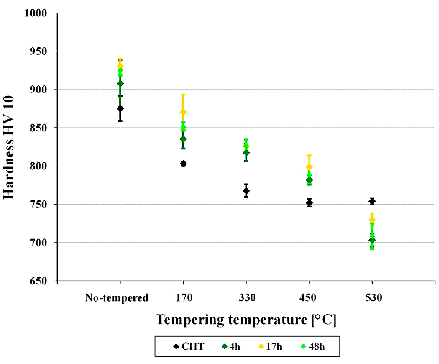
The hardness of conventionally quenched steel was 803, 768, 752, and 754 HV 10 after tempering at temperatures of 170, 330, 450, and 530°C, respectively. In other words, the hardness of conventionally heat-treated steel first decreases with increasing tempering temperature, and then it is preserved, almost constantly (at a level of 750 HV 10), when tempered at temperatures normally used for secondary hardening. In contrast, the steel after application of sub-zero treatments manifested higher hardness values, and this tendency was maintained up to the tempering temperature of 450°C. The most significant hardness improvement was recorded for the steel treated for 17 hours. For the specimens tempered at 530°C, however, the hardness of sub-zero treated steel was lower than what was obtained by CHT.
These results are in line with those obtained by investigations of tempering response of the steel after SZT at minus-196°C [12,20,21]. On the other hand, a strong variance between the tempering responses of the steel treated at minus-75°C and the steel treated at minus-140°C is evidenced. For the latter SZT temperature, it has been reported recently that hardness of the material was improved significantly within the whole range of tempering regimes used [22].
The flexural strength values obtained by three-point bend tests of samples having the microstructures according to Figure 4 are shown in Figure 6. It can be seen that the mean values of the flexural strength range between 3,300 and 3,700 MPa. The ranges of statistical uncertainty (at a probability level of 5 percent) overlap noticeably, suggesting the tempering has only a marginal effect on the flexural strength of SZT steel.
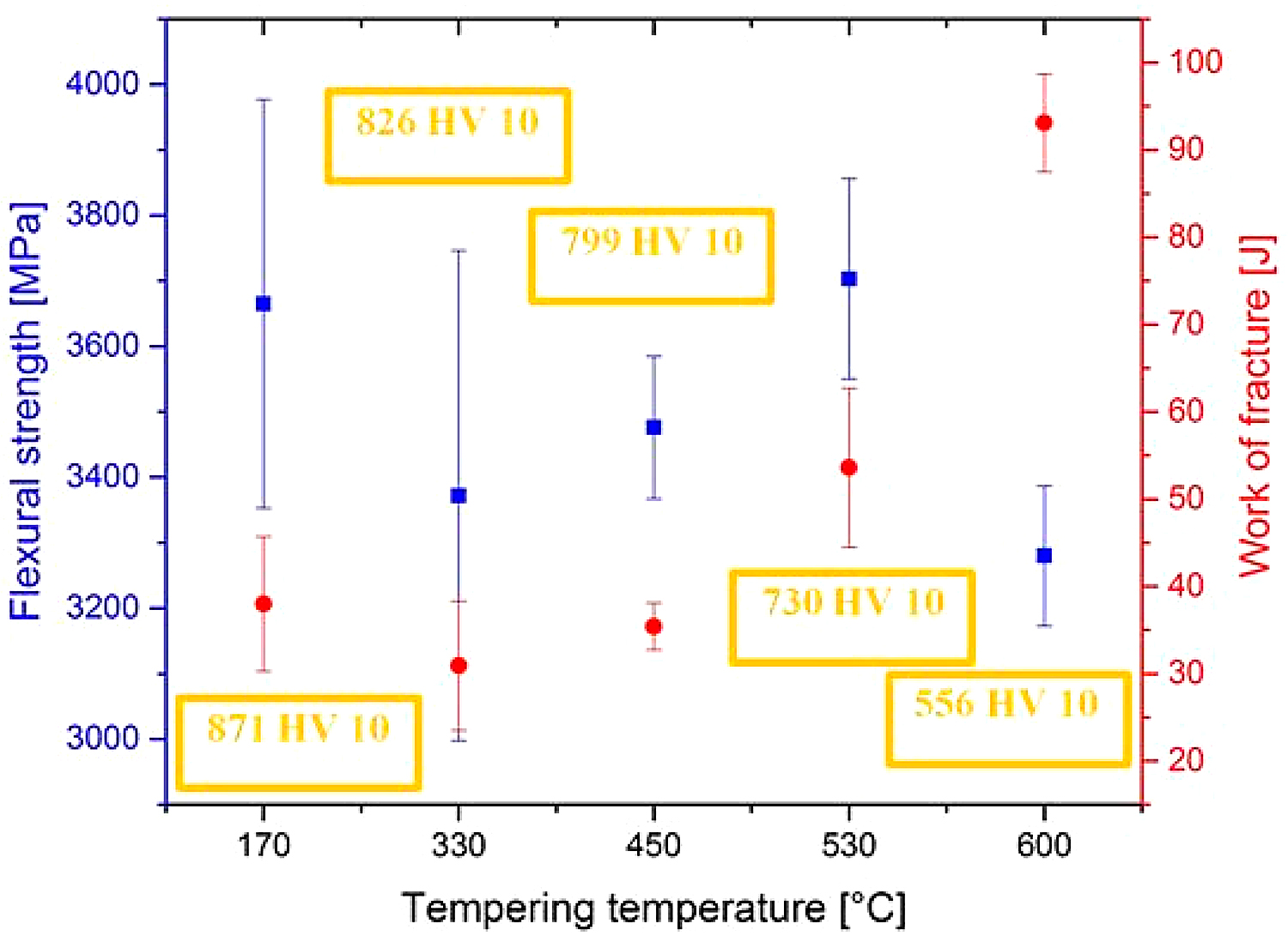
The work of fracture values of the steel tempered at 170, 330, and 450°C lie within the range of statistical uncertainty in Figure 6, suggesting low-temperature tempering does not influence this characteristic significantly. On the other hand, the work of fracture increases when the steel is tempered at temperature 530°C and above. This can be associated with hardness decrease (as indicated in Figure 6), and thus with more extensive (compared to what occur during testing of specimens tempered at lower temperatures) plastic deformation of the matrix.
It is also well visible that the Wof values follow closely the values of flexural strength, but only up to the tempering temperature of 530◦C (peak of secondary hardness). For the specimens tempered at 600°C, however, this relationship is no more valid. At this place, it should be noted the Vanadis 6 steel belongs to the group of brittle steels when tempered at temperatures up to the secondary hardness peak; in these cases, the obtained values of flexural strength are an indirect measure of its toughness. On the other hand, the flexural strength loses the characteristic of toughness when the hardness of the steel decreases. This is the case of “overtempering” of the steel, i.e., when the steel is tempered at temperatures beyond the secondary hardness peak, for instance, at 600°C.
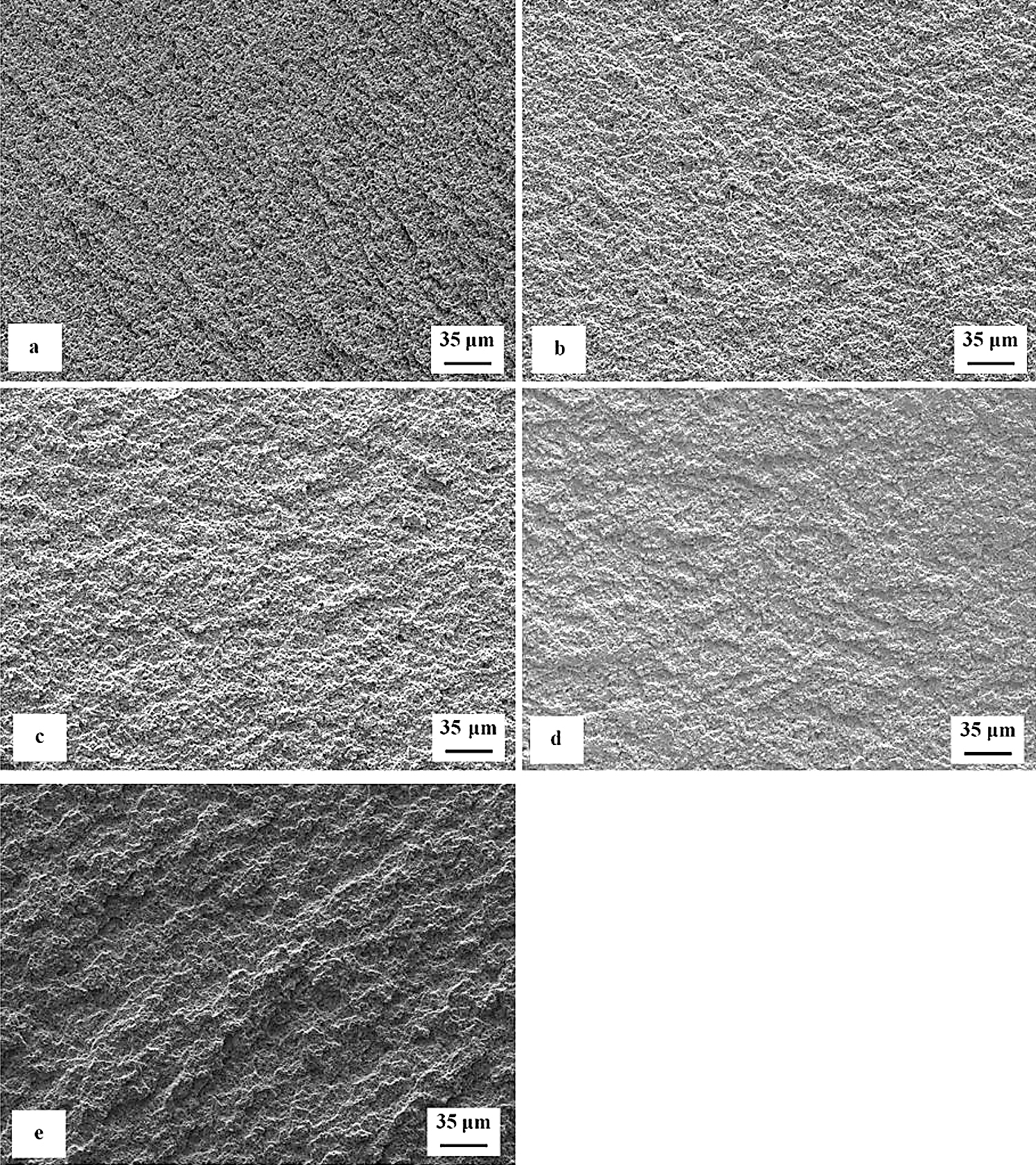
Figure 7 is a compilation of SEM micrographs showing fracture surfaces of flexural strength specimens that were sub-zero treated at minus-75°C for 17 hours and subsequently tempered at different temperatures. With respect to the surface morphology, the fracture surfaces can be divided into two groups. The fracture surfaces of the first group of specimens appear relatively flat with only very limited roughness caused by a strong difference between the fracture behavior of the matrix and carbides, Figure 7a-c. In contrast, the fracture surfaces (second group) of the specimens tempered at 530 and 600°C (the latter one in particular) manifest much more pronounced indications of plastic deformation of the matrix, Figure 7d,e. Here it should be noted the steel hardness decreased (and the plasticity expectedly increased) with increasing the tempering temperature in Figure 6. This correlates well with the earlier-mentioned morphology of fracture surfaces. In other words, the fracture surfaces appear relatively flat and shiny when the steel has higher hardness, but their topography increases with a hardness decrease (i.e., with increasing the tempering temperature).
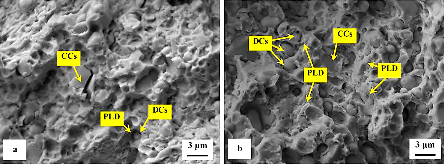
Detailed SEM fractographs in Figure 8 clearly delineate the differences between the fracture surfaces obtained by testing of specimens tempered at 170 and 600°C. A relatively flat morphology of the fracture surface with only very limited plastic deformation of the matrix is visible in Figure 8a. The presence of micro-plastic deformation is only visible at the sites where decohesion at the matrix/carbide interface took place during the crack propagation. The sites with local micro-plastic deformation are mainly in close vicinity to smaller carbides, which act as decohesion sites at the earlier-mentioned interfaces. These carbides are denoted as decohesive carbides (DCs). Other carbide particles (the coarser ones in most cases) are cleaved, and they are denoted as “cleaved carbides, CCs.” In contrast to the fracture surface shown in Figure 8a, the fracture of the specimen tempered at 600°C manifests much more pronounced plastic deformation shown in Figure 8b. However, the role of particular carbides in the crack propagation is maintained and is almost the same as shown in Figure 8a.
The obtained flexural strength values for differently sub-zero treated and tempered specimens are summarized in Figure 9. It is shown that the treatment at minus-75°C gave rather higher flexural strength than the conventional heat treatment. This is somewhat surprising at first glance, since one would expect a decrease in flexural strength rather than a slight increase due to the application of SZT.
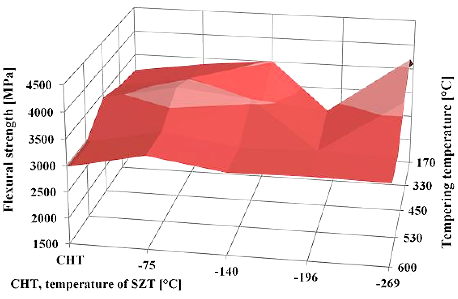
To explain this, it should be noted that Vanadis 6 steel contains 20.2, 7.6, 4.8, 2.1, and 6.3 vol % of retained austenite after CHT, SZT at minus-75°C, SZT at minus-140°C, SZT at minus-196°C, and SZT at minus-269°C, respectively (all the SZTs were carried out for a 17-hour duration) [12,26]. Retained austenite is considered a soft microstructural feature, and one can expect its beneficial effect on toughness (and flexural strength). This may, for instance, partly explain the better flexural strength of the conventionally heat-treated material, as well as the material SZT at either minus-140 or minus-269°C, than was obtained by SZT at minus-196°C. However, this does not bring an answer to the improvement of flexural strength by SZT at minus-75°C, compared to CHT steel. As mentioned earlier, sub-zero treatment at minus-75◦C produces a much higher population density of small globular carbides than CHT, which in turn leads to the formation of an increased number of matrix/carbide interfaces. The population density of small globular carbides decreases with tempering, despite remaining much higher than what can be obtained by CHT. In the steel samples with a higher population density of carbides, the crack propagation is probably more associated with micro-plastic deformation of a matrix (as Figure 8 clearly demonstrates); hence, an enhanced carbide count is an important factor responsible for improvements of flexural strength.
Finally, a few words should be written to the fact that the treatments at either minus-140 or minus-269°C lead to nearly equal or slightly better flexural strength than what is obtained in the present study. It has been reported recently that the treatment at minus-140°C for 17 hours results in the retained austenite amount of about 4.3 vol% [22]. The latest measurements fixed the γR amount to 6.3 vol% in the Vanadis 6 steel treated in liquid helium. This is two times (for minus-140°C SZT) or three times (for minus-269°C) more than what was obtained by SZT at minus-196°C, but only of approximately 60% or 85% in comparison with the values reported here for SZT at minus-75°C. One can thus expect rather opposite tendency with respect to the changes of flexural strength; however, the treatment at minus-140°C (for instance) produces the greatest population density of SGCs, which more than fully compensates the toughness loss resulting from the reduction of retained austenite.
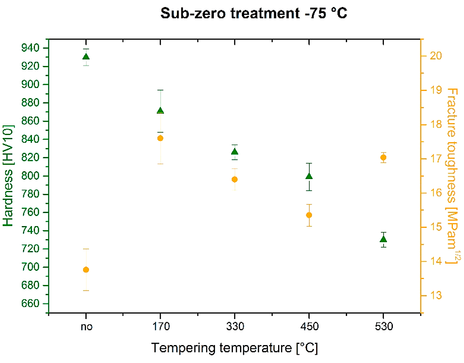
The relation between fracture toughness and hardness as a function of tempering temperature is seen in Figure 10. The fracture toughness values were 13.76 ± 0.61, 17.60 ± 0.75, 16.40 ± 0.32, 15.35 ± 0.32, and 17.04 ± 0.15 MPa × m1/2 for specimens prior-to-tempering, tempered at 170, 330, 450, and 530°C, respectively. The lowest KIC values were determined for prior-to-tempering specimens, which had the highest hardness. This is logical because the hardness is the key factor that influences the fracture toughness, and it is generally accepted that metals with high hardness usually manifest low fracture toughness level and vice versa [20,33]. However, the values of KIC and hardness obtained by testing of tempered specimens do not obey this rule. It is, for instance, shown that the fracture toughness is high for the steel tempered at 170°C despite its high hardness. Further, the KIC decreases along with the hardness when the tempering temperature is increased to either 330 or 450°C. An increase in KIC was recorded only for the steel tempered at 530°C, but at a lower hardness value.
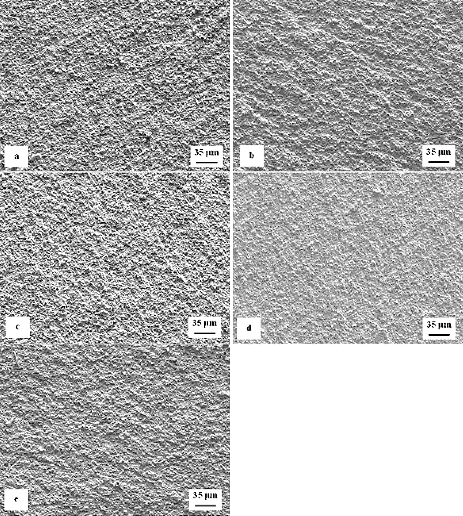
The analysis of fracture surfaces provides a more comprehensive insight into the variations of fracture toughness with tempering. Figure 11 is a compilation of representative SEM micrographs of the fractured KIC specimens that were SZT at minus-75°C and no-tempered or tempered at different temperatures. The fracture surfaces of all the specimen-manifest symptoms that are typical for hard and brittle steels; they appear flat, shiny, and relatively smooth. However, more thorough investigation reveals differences on the topography of fractured surfaces. The surface of no-tempered specimen (Figure 11a) manifests much finer topography compared with the fractured surfaces of other specimens (Figure 11b-e). This can be attributed to the differences in fracture toughness-no-tempered specimens that have the lowest KIC values, and tempering leads to moderate increase in this characteristic.
Detailed SEM micrographs in Figure 12 were acquired from the specimen that was not tempered after sub-zero treatment. The image in Figure 12a assists in seeing the fracture surface manifests typical morphology for hard steel. It contains a great number of micro-voids and holes, which correspond to the extraction of SGCs (in particular) from the fracture surface during the crack propagation. The formation of micro-voids is associated with local plastic deformation of the matrix. However, the capability of the matrix to be deformed plastically is very limited as seen in Figure 12b. There is a great number of sites with cleavage fracture mechanism apparent in the matrix as Figure 12c illustrates. The micrograph in Figure 12b also depicts the difference in behavior of carbides during the crack propagation. Some carbide particles (mainly the coarsest ones) were cleaved while others assisted the decohesion mechanism of the crack propagation. This is similar to what was discovered for the flexural strength specimens in Figure 8.
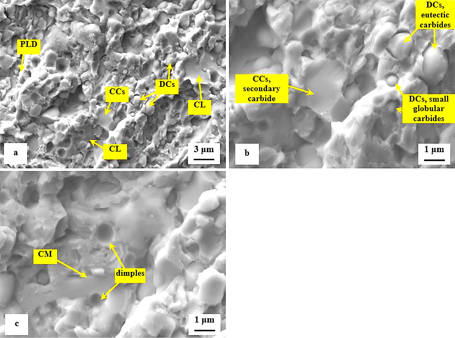
The role of particular carbides in the fracture propagation can be assessed with the help of recent investigations. It has been published recently that the coarsest particles belong mostly to the group of secondary carbides and that their nature is hexagonal M7C3 [7,11,12,22]. The finer particles are either eutectic carbides (MC-carbides with cubic crystallographic structure) or small globular carbides (cementite M3C) [7]. Casellas et al. clearly demonstrated that lower symmetry of the hexagonal crystalline lattice (as compared with cubic MC phase) results in low fracture toughness of M7C3, and correspondingly in large scatter of its values (0.5-4.5 MPa × m1/2) [34]. Moreover, Fukaura et al. [35] proved the size of the carbides plays an important role in their fracture propagation manner, namely that coarser particles are much more amenable to the cleavage than the finer carbides. In Vanadis 6 steel, the mean spherical diameter of the M7C3 particles is of around 2.5–2.8 μm while the MC carbides have size within the range 1.6–1.9 μm [26]. The size of small globular carbides, SGCs, is much smaller, below 0.5 µm. These facts assist to delineate the role of different carbides in fracture propagation as Figure 12 illustrates. Larger size and crystallographic anisotropy of M7C3 make this carbide more brittle than the MC (or M3C), despite that the hardness of M7C3 is lower than that of MC [34]. This is why the most part of cleaved carbides are the SCs (M7C3) while a dominant number of ECs (and almost all the SGCs) is unaffected by the crack propagation, thus, assisting decohesion at the matrix/carbide interfaces.
The second series of detailed SEM micrographs, Figure 13, depicts the details of fracture propagation in the specimen that was sub-zero treated and subsequently tempered at 530°C. It is worth noting the fractured surfaces of specimens tempered at other temperatures did not differ significantly from that in Figure 13. Compared to the fracture surface of the prior-to-tempering specimen in Figure 12, the fracture surface of the tempered one contains much greater area fraction of micro-plastically deformed matrix seen in Figure 13a. Further, there are cleaved carbides (CCs) and decohesive carbides present.
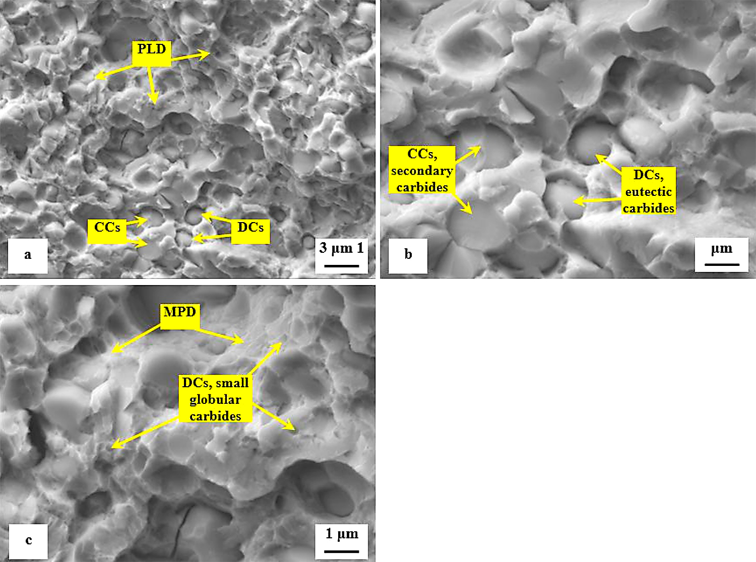
The high-resolution SEM micrograph in Figure 13b shows details of cleaved secondary carbides (CCs) and decohesive eutectic carbide particles (ECs), suggesting the role of particular carbides in the fracture propagation is very similar to the case of the prior-to tempering specimen, see Figure 12. In other words, the difference in fracture toughness (13.76 ± 0.61 MPa × m1/2 for the prior-to tempering steel versus 17.04 ± 0.15 MPa × m1/2 for the steel tempered at 530°C) does not play a significant role in the fracture propagation mode of carbide particles. In contrast, mentioned difference in fracture toughness values is reflected in the matrix behavior. As Figure 13c illustrates, the fracture propagation on the matrix is associated with micro-plastic deformation, and the cleavage takes only a minor role. The differences in the fracture toughness, and correspondingly in the morphology of fracture surfaces of differently tempered specimens, can be explained considering the material microstructure. Table 3 shows the examined steel contains 7.6 ± 0.4 vol% of retained austenite in the prior-to-tempering state. The retained austenite is relatively soft, thus prone to plastic deformation. For instance, Putatunda [33] reported the retained austenite has a beneficial effect on the fracture toughness of high-carbon steels. However, the Vanadis 6 steel also contains a high amount of hard and brittle “pre-aged” martensite in the prior-to-tempering state. (It is worth noting aging of the martensite in sub-zero-treated high-carbon steels was many times experimentally proved, e.g. [14,15,26,36].) This makes the steel brittle. Berns and Broeckmann [1], Das et al. [19], and Ptačinová et al. [21] found the crack has a strong tendency to follow the interfaces between matrix and carbides when propagates during testing of ledeburitic steels. As a result, a micro-plastic deformation of the matrix occurs, which slightly improves the fracture toughness. Nevertheless, beneficial effects of retained austenite and increased population density of carbides cannot compensate the high brittleness of pre-aged martensite, hence, the material manifests very low fracture toughness as a consequence. Finally, it should be underlined that this finding is in line with the obtained results on the same steel but processed at different SZT temperatures as Figure 14 illustrates. Finally, it should be underlined that this finding is in line with the obtained results by the KIC testing of the same steel that was processed at other SZT temperatures as Figure 14 illustrates.
Tempering reduces the material hardness seen in Figure 5, and one can thus expect an increase of fracture toughness. Increased fracture toughness was really recorded for sub-zero treated and subsequently tempered steel specimen seen in Figure 10. The clarification of this issue is relatively complex: On one hand, the amount of soft retained austenite is either moderately reduced (for the steel tempered at 170 or 330°C) or this phase is almost completely removed (after application of higher tempering temperatures), seen in Table 3. Also, tempering reduces the population density of small globular carbides, seen in Table 2 and in Figure 3. On the other hand, the martensite undergoes significant softening, which makes it more amenable to deform plastically. The resulting fracture toughness values are then a result of competition between the mentioned three phenomena. The increase of KIC values can be mainly ascribed to the martensite softening, as this phase is the major one in the material. Increase in fracture toughness is reflected in more pronounced topography of fractured surfaces (and in more visible dimples on fracture surfaces at the same time). Compare Figure 11a with Figure 11b-e or Figure 12 with Figure 13.
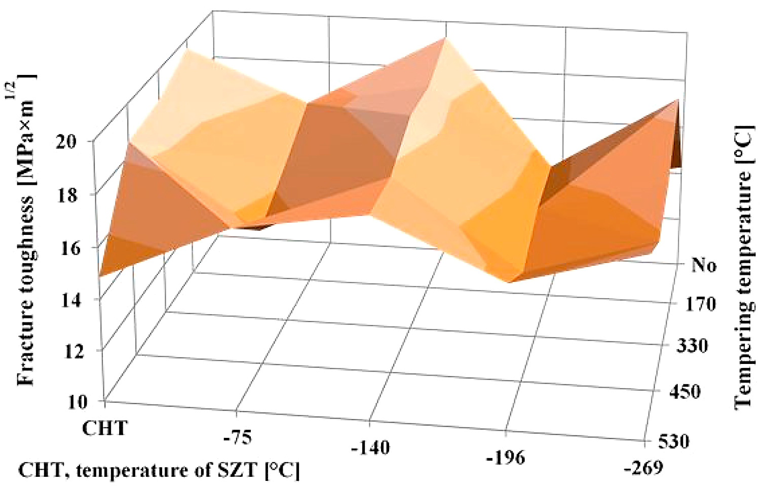
A very interesting comparison of the current results with those obtained by testing of CHT steel and the steel that was subjected to SZT at minus-140, minus-196, or minus-269°C is provided in Figure 14. It is shown that the SZT at minus-140°C gave the best results that are fully comparable with conventionally heat-treated steel but at a significantly increased hardness as reported in [22]. Treatments at either the temperatures of boiling nitrogen or helium resulted rather in lower fracture toughness values.
A reliable explanation of the variations in fracture toughness is a very complex issue. In brief, the resulting fracture toughness value of ledeburitic tool steels is always a result of competition between three effects: 1) retained austenite amount, which undoubtedly acts in favor of higher KIC, 2) state of the martensite (KIC decrease), and 3) population density of small globular carbides (increase of KIC) [22]. CHT steel contains about 20 vol% of the retained austenite in the prior-to-tempering state, and the retained austenite amount is nearly constant up to the tempering temperature of 500°C [12]. Even though the population density of SGCs is very low in CHT steel (as compared with the steel after SZTs), it is more than satisfactorily compensated by the retained austenite amount. Application of SZTs reduces the retained austenite amount considerably (with the minimum value for SZT at minus-196°C) and increases the population density of SGCs (with the maximum for the SZT at minus-140°C). The results in Figure 14 imply the reduction of retained austenite is almost fully compensated by a much higher population density of SGCs for the steel after SZT at minus-140°C, while other SZTs do not lead to a high enough population density of carbides needed to compensate the impact of reduced retained austenite amount on the resulting KIC value.
Finally, it should be noted these considerations do not take into account the state of the martensite. In the state after CHT (and prior-to-tempering), the martensite was found to be “pre-aged,” but it did not contain any carbide precipitates [7]. In contrast, the martensite after SZTs contained nano-sized, coherent transient carbides ([12,26]. However, it is hard or practically impossible to provide an exact assessment of the difference between impacts of these two martensite states on the fracture toughness of the steel since it also contains the retained austenite and several carbide types. The situation is very similar in the case of tempered steel Vanadis 6 because tempering leads to acceleration of precipitation rate at low-tempering temperatures but rather to delayed precipitation at high temperatures (around 500°C) [11,12,26]. But, an exact quantification of precipitates is almost impossible.
4 Conclusions
The impact of sub-zero treatment at the temperature of minus-75°C and subsequent tempering on the microstructure, hardness, flexural strength and fracture toughness was investigated. The main obtained results can be summarized as follows:
The population density of small globular carbides is increased by the application of SZT at minus-75°C by the factor from the range 2.5 and seven.
Retained austenite amount is reduced by this kind of treatment to an approximately one third as compared with conventional room temperature quenching.
The bulk hardness of the steel is increased by SZT at minus-75°C, by 30-60 HV10. Improved steel hardness is maintained up to the tempering temperature of 450°C while tempering at 530°C leads to more significant hardness reduction than what is obtained by conventional heat treatment.
The flexural strength of SZT steel ranges between 3,300 and 3,700 MPa. The level of tempering temperature has only a little impact in the flexural strength.
The fracture toughness of sub-zero treated no-tempered steel is very low. However, it increases with the tempering application, and reaches relatively high values of around 17 MPa × m1/2 after tempering to the secondary hardness peak.
In summary, the application of SZT at minus-75°C may bring some benefits into heat treatment of tool steels. However, the obtained microstructures and values of mechanical properties are lower as compared, for instance, with those obtained by treatment at minus-140°C.
Author Contributions
Funding acquisition, P.J.; Microstructural investigation, L.R.-T., P.J.; X-ray diffraction, M.K.; Dilatometry. J.K.; Flexural strength, fracture toughness testing, I.D.; Supervision, P.J.; Writing—original draft, review, editing, P.J., I.D.
Funding
The authors acknowledge that the paper is a result of experiments realized within the project VEGA 1/0264/17. In addition, this publication is the result of the project implementation “Centre for Development and Application of Advanced Diagnostic Methods in Processing of Metallic and Non-Metallic Materials – APRODIMET”, ITMS: 26220120014, supported by the Research & Development Operational Programme funded by the ERDF.
Conflicts of Interest
The authors declare no conflict of interest.
References
- Berns, H.; Broeckmann, C. Fracture of Hot Formed Ledeburitic Chromium Steels. Eng. Fract. Mech. 1997, 58, 311-325.
- Das, D.; Ray, K.K. Structure-property correlation of cub-zero treated AISI D2 steel. Mater. Sci. Eng. A 2012, 541, 45-60.
- Amini, K.; Akhbarizadeh, A.; Javadpour, S. Investigating the effect of the quench environment on the final microstructure and wear behaviour of 1.2080 tool steel after deep cryogenic heat treatment. Mater. Des. 2013, 45, 316-322.
- Das, D.; Ray, K.K.; Dutta, A.K. Influence of temperature of sub-zero treatments on the wear behaviour of die steel. Wear 2009, 267, 1361-1370.
- Surberg, C.H.; Stratton, P.F.; Lingenhoele, K. The effect of some heat treatment parameters on the dimensional stability of AISI D2. Cryogenics 2008, 48, 42-47.
- Akhbarizadeh, A.; Javadpour, S.; Amini, K.; Yaghtin, A.H. Investigating the effect of ball milling during the deep cryogenic heat treatment of the 1.2080 tool steel. Vacuum 2013, 90, 70-74.
- Jurči, P.; Dománková, M.; Čaplovič, L.; Ptačinová, J.; Sobotová, J.; Salabová, P.; Prikner, P.; Šuštaršič, B.; Jenko, D. Microstructure and hardness of sub-zero treated and no tempered P/M Vanadis 6 ledeburitic tool steel. Vacuum 2015, 111, 92-101.
- Amini, K.; Akhbarizadeh, A.; Javadpour, S. Investigating the effect of holding duration on the microstructure of 1.2080 tool steel during the deep cryogenic treatment. Vacuum 2012, 86, 1534-1540.
- Tyshchenko, A.I.; Theisen, W.; Oppenkowski, A.; Siebert, S.; Razumov, O.N.; Skoblik, A.P.; Sirosh, V.A.; Petrov, J.N.; Gavriljuk, V.G. Low-temperature martensitic transformation and deep cryogenic treatment of a tool steel. Mater. Sci. Eng. A 2010, 527, 7027-7039.
- Villa, M.; Pantleon, K.; Somers, M.A.J. Evolution of compressive strains in retained austenite during sub-zero Celsius martensite formation and tempering. Acta Mater. 2014, 65, 383-392.
- Jurči, P. Sub-Zero Treatment of Cold Work Tool Steels–Metallurgical Background and the Effect on Microstructure and Properties. HTM J. Heat Treat. Mater. 2017, 72, 62-68.
- Jurči, P.; Dománková, M.; Hudáková, M.; Ptačinová, J.; Pašák, M.; Palček, P. Characterization of microstructure and tempering response of conventionally quenched, short- and long-time sub-zero treated PM Vanadis 6 ledeburitic tool steel. Mater. Charact. 2017, 134, 398-415.
- Stratton, P.F. Optimizing nano-carbide precipitation in tool steels. Mater. Sci. Eng. A 2007, 449-451, 809-812.
- Van Genderen, M.J.; Boettger, A.; Cernik, R.J.; Mittemeijer, E.J. Early Stages of Decomposition in Iron-Carbon and Iron-Nitrogen Martensites: Diffraction Analysis Using Synchrotron Radiation. Metall. Trans. A 1993, 24, 1965-1973.
- Preciado, M.; Pellizzari, M. Influence of deep cryogenic treatment on the thermal decomposition of Fe-C martensite. J. Mater. Sci. 2014, 49, 8183-8191.
- Collins, D.N.; Dormer, J. Deep Cryogenic Treatment of a D2 Cold-work Tool Steel. Heat Treat. Met. 1997, 3, 71-74.
- Wierszyllowski, I. The Influence of Post-quenching Deep Cryogenic Treatment on Tempering Processes and Properties of D2 Tool Steel. Studies of Structure, XRD, Dilatometry, Hardness and Fracture Toughness. Defect Diffus. Forum 2006, 258-260, 415-420.
- Rhyim, Y.M.; Han, S.H.; Na, Y.S.; Lee, J.H. Effect of Deep Cryogenic Treatment on Carbide Precipitation and Mechanical Properties of Tool Steel. Solid State Phenom. 2006, 118, 9-14.
- Das, D.; Sarkar, R.; Dutta, A.K.; Ray, K.K. Influence of sub-zero treatments on fracture toughness of AISI D2 steel. Mater. Sci. Eng. A 2010, 528, 589-603.
- Sobotová, J.; Jurči, P.; Dlouhý, I. The effect of sub-zero treatment on microstructure, fracture toughness, and wear resistance of Vanadis 6 tool steel. Mater. Sci. Eng. A 2016, 652, 192-204.
- Ptačinová, J.; Sedlická, V.; Hudáková, M.; Dlouhý, I.; Jurči, P. Microstructure Toughness relationships in sub-zero treated and tempered Vanadis 6 steel compared to conventional treatmen. Mater. Sci. Eng. A 2017, 702, 241-258.
- Jurči, P.; Dˇ urica, J.; Dlouhý, I.; Horník, J.; Planieta, R.; Kralovič, D. Application of −140°C Sub-Zero Treatment For Cr-V Ledeburitic Steel Service Performance Improvement. Metall. Mater. Trans. A 2019, 50, 2413-2434.
- Kumar, S.; Nahraj, M.; Bongale, A.; Khedkar, N.K. Effect of deep cryogenic treatment on the mechanical properties of AISI D3 tool steel. Int. J. Mater. Eng. Innov. 2019, 10, 98-113.
- Reitz, W.; Pendray, J. Cryoprocessing of Materials: A Review of Current Status. Mater. Manuf. Process. 2001, 16, 829-840.
- Gavriljuk, V.G.; Theisen, W.; Sirosh, V.V.; Polshin, E.V.; Kortmann, A.; Mogilny, G.S.; Petrov, Y.N.; Tarusin, Y.V. Low-temperature martensitic transformation in tool steels in relation to their deep cryogenic treatment. Acta Mater. 2013, 61, 1705-1715.
- Ďurica, J.; Ptačinová, J.; Dománková, M.; Čaplovič, L.; Čaplovičová, M.; Hrušovská, L.; Malovcová, V.; Jurči, P. Changes in microstructure of ledeburitic tool steel due to vacuum austenitizing and quenching, sub-zero treatments at minus-140°C and tempering, Vacuum 2019. 2019.
- Zurecki, Z. Cryogenic Quenching of Steel Revisited. In Proceedings of the 23rd Heat Treating Society Conference, Pittsburgh, PA, USA, 26–28 September 2005; pp. 106-114.
- ASTM E975-13. Standard Practice for X-Ray Determination of Retained Austenite in Steel with Near Random Crystallographic Orientation; ASTM Book of Standards: West Conshohocken, PA, USA, 2004; Volume 3.01.
- CSN EN ISO 6507-1. Metallic Materials – Vickers Hardness Test – Part 1: Test Method; Office for Technical Standardization, Metrology and State Testing: Prague, Czech Republic, 2018.
- Jurči, P.; Dlouhý, I. Fracture Behaviour of P/M Cr-V Ledeburitic Steel with Different Surface Roughness. Mater. Eng. 2011, 18, 36-43.
- CSN EN ISO. Hardmetals – Determination of Transverse Rupture Strength; Office for Technical Standardization, Metrology and State Testing: Prague, Czech Republic, 2009.
- ISO 12135. Metallic Materials – Determination of Plane Strain Fracture Toughness. 2010. Available online: https://www.iso.org/standard/60891.html (accessed on 1 November 2016).
- Putatunda, S.K. Fracture toughness of a high carbon and high silicon steel. Mater. Sci. Eng. A 2001, 297, 31-43.
- Casellas, D.; Caro, J.; Molas, S.; Prado, J.M.; Valls, I. Fracture toughness of carbides in tool steels evaluated by nanoindentation. Acta Mater. 2007, 55, 4277-4286.
- Fukaura, K.; Yokoyama, Y.; Yokoi, D.; Tsuji, N.; Ono, K. Fatigue of cold-work tool steels: Effect of heat treatment and carbide morphology on fatigue crack formation, life, and fracture surface observations. Metall. Mater. Trans. A 2004, 35, 1289-1300.
- Cheng, L.; Brakman, C.M.; Korevaar, B.M.; Mittemeijer, E.J. The tempering of iron-carbon martensite; dilatometric and calorimetric analysis. Metall. Trans. A 1988, 19, 2415-2426.


 general practice for CQI-9 and AMS2750E")


