


Quality and efficiency in heat-treatment operations requires accurate temperature measurement. Specifying thermocouple wire and thermocouples carefully will lead to greater temperature measurement accuracy and less scrap or re-work.
First, consider whether the need is for thermocouple cable or for thermocouple extension cable. Thermocouple cable is made to survive inside the furnace and may be used to form the measuring junction or “hot junction.” It requires insulation and jacketing material that can withstand the process temperatures. It must be used where the temperatures are extreme.
Thermocouple extension cables are used when the process control instrumentation or recording device is at an extended distance. They complete the thermocouple circuit back to the reference junction or “cold junction,” which exists inside the instrumentation.
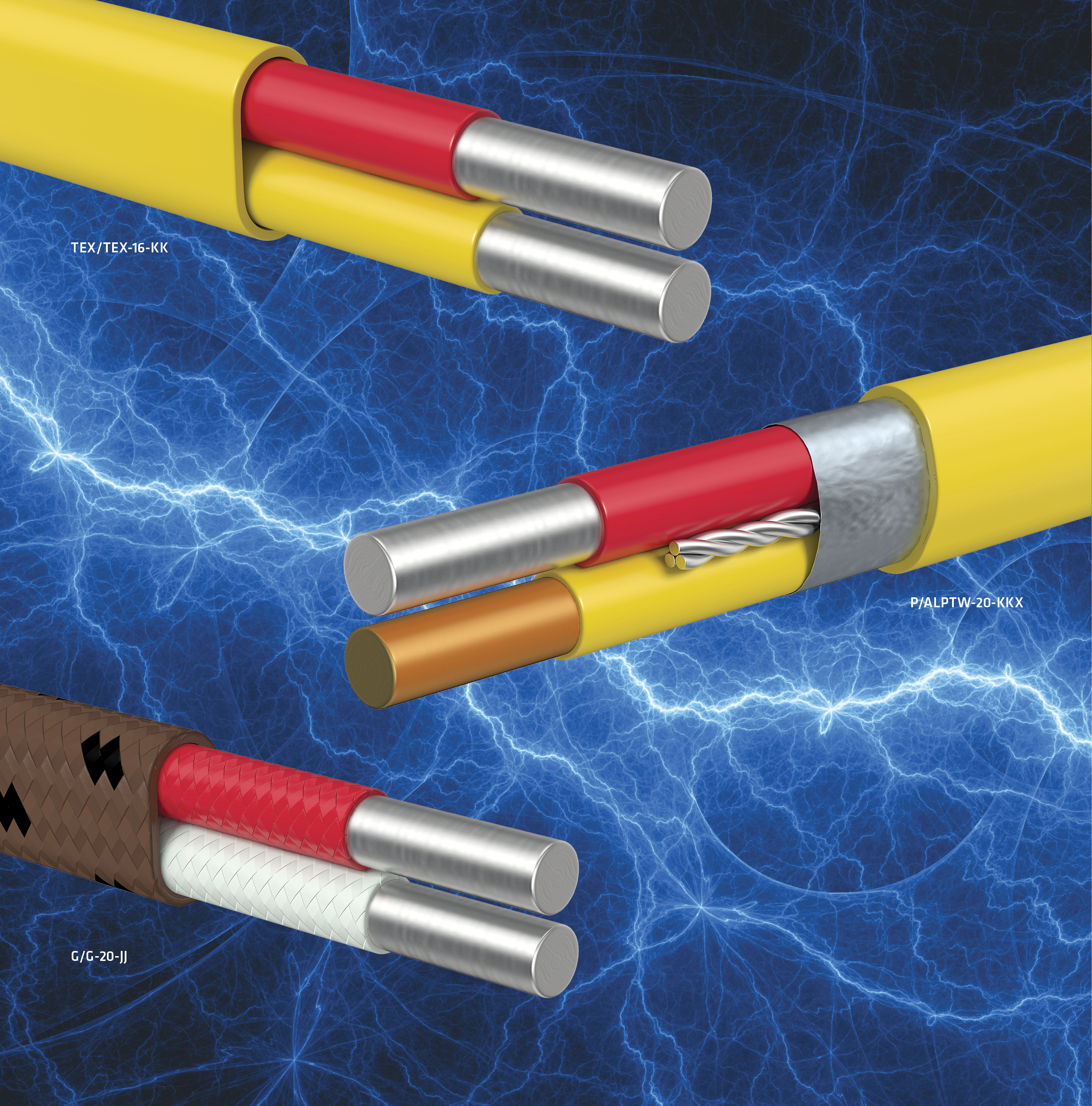
A thermocouple connector makes the transition between the thermocouple cable and its extension. The “true” or “high-temperature” thermocouple cable is wired into the plug (male) half of the connector. The extension grade cable is wired into the jack (female) half of the connector. All components need to be of the same type; that is for a Type K thermocouple, the cable and connector must be type K, and the extension cable must be type KX.
Extension cables
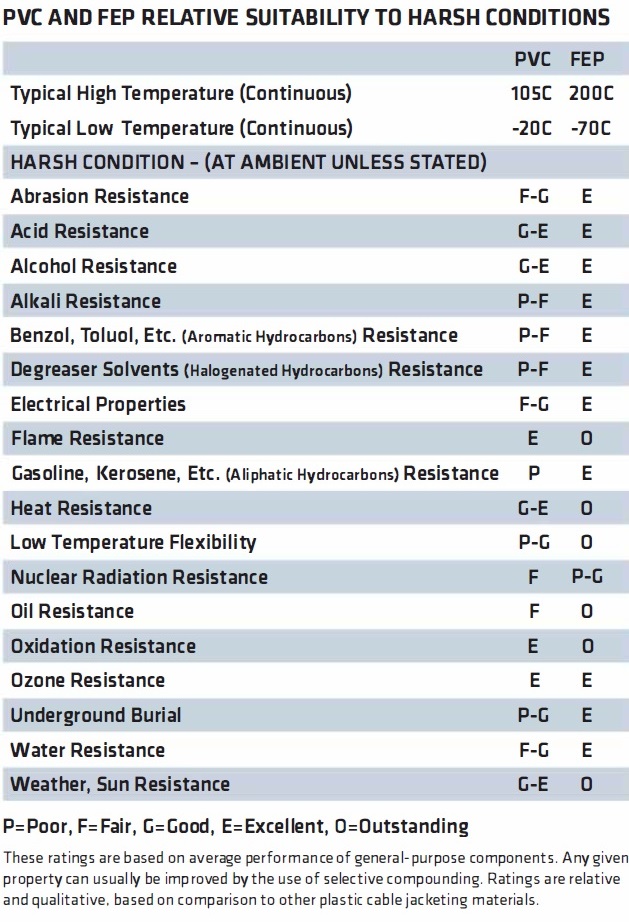
Because thermocouple extension cables are away from the furnace; where temperatures are at or close to ambient, they are made with PVC (105°C) or FEP (200°C) or other relatively low-temperature insulation materials. See Table 1 for the relative properties of FEP vs. PVC in harsh environments for guidance on which insulation and jacket material is right for your application.
Extension cables are not subjected to the extreme temperatures and temperature cycling that cause calibration drift and do not require frequent replacement. Extension cables simply carry the Seebeck EMF generated back to the instrumentation. Where best practices require limited life and routine replacement of thermocouples measuring high temperature due to calibration drift, it is not necessary to replace their extensions on the cold side of the connector. Only the high temperature “true” thermocouple cable on the hot side of the connector is replaced. Extension grade thermocouple conductors are not calibrated above 400°F (204°C) or 212°F (100°C) for TX) — again, since these are only run through ambient environment.
Extension cables are still part of the thermocouple circuit and carry the Seebeck EMF generated at the measuring junction back to the reference junction existing within the instrument. So, the conductor alloy must be compatible with that of the thermocouple. For base-metal thermocouples, this means thermocouple types T, J, E, K, or N must only be extended with extension grades TX, JX, EX, KX, or NX respectively. For these base thermocouple circuits, the alloy metals of the extension grade conductors [1] are substantially the same as thermocouple grade alloys and have approximately the same thermoelectric properties. However, they are not calibrated above 400°F as stated earlier.
Noble Metal Thermocouple Extension
Noble metal thermocouples type R, S, or B are used when measuring higher temperatures. Their extension grades are still referred to as types RX, SX, or BX respectively. However, here the alloys differ from the noble-metal thermocouple but still have approximately the same thermoelectric properties. Common copper instrumentation cable must not be used as thermocouple extension cable for the reasons given above.
Cable Listings — Electrical Code Requirements
Extension grade thermocouple cable is typically run where the circuit is relatively long and might be permanently installed in cable tray, conduit, or other raceways. As such, it is subject to the regulations governing all instrumentation and control wiring for the facility, probably the National Electrical Code (NEC, NFPA 70) Article 725 or Article 300. This in turn requires the cable to be listed by a nationally recognized testing laboratory (NRTL). The cable listing requirements are either PLTC (Power Limited Tray Cable, Article 725) for 300V cable raceways and enclosures; or TC (Tray Cable, Article 300) for 600V cable raceways and enclosures. The voltage rating has more to do with the facility infrastructure and where the thermocouple extension cables will be routed and terminated than with the thermocouple circuit itself. It may be run alongside other cables. NEC installation practices require all cables rated 600V and higher cables be segregated. This is why a facility may require 600V rating on thermocouple extension cables — because that is their infrastructure. The circuit voltage will still be only down at signal levels. Most thermocouple extension cables are listed as PLTC, which technically rates them for 300V, although, again, the actual circuit voltage will be only at signal levels. The voltage rating is not printed on PLTC cables, per UL marking rules. In ambient temperature and benign environments (which is typical), the insulation and jacket are PVC or other low-temperature materials, and the cables are usually listed as type PLTC. In extreme or harsh environments where PVC may not be suitable, fluoropolymer FEP insulation and jacket materials can be selected. FEP is excellent relative to PVC and other plastic materials where exposure to harsh environments such as solvents, acids or alkali, gasoline, direct sunlight, water, or direct burial conditions are possible. Cables in such harsh environments may be deemed special-application cables, and NEC listings may not apply. Table 1 indicates the relative suitability of PVC and FEP in harsh environments.
Extension cables are 22AWG minimum size; however, larger sizes 20AWG, 18AWG, and 16AWG are also common. The minimum size requirement is so they may be listed as National Electrical Code (NEC) cable type PLTC. This may mean the extension is a larger wire size than the thermocouple itself, which runs to the measuring junction. The larger wire size is better suited to the relatively longer portion of the circuit since it will have a lower resistance for circuit length. So, an increased size may be for circuit design purposes, and not only to meet the requirements of PLTC.
Electrical noise
Extension cables are subjected to electrical noise. Pairs should be optimally be twisted, and the cable should be shielded. These cables are usually longer cable runs through the factory. They may be alongside electrically noisier power, control, and instrumentation cables operating at higher voltages. They may be run past any number of generators, motors, lights, or other sources of electrical noise. All this electro-magnetic noise could interfere with very low voltage thermocouple signal. For this reason, thermocouple extension cables should be shielded. When a cable is comprised of multiple pairs, each pair should be twisted. Twisting the pairs defeats common-mode noise. Shielding is typically an aluminum-foil tape that absorbs outside noise and a tinned copper wire that “drains” the foil and carries the noise away as electrical current to ground. The drain wire is terminated to ground at one end of the cable run. The aluminum foil tape is polyester on one side, which serves two purposes: The polyester layer adds strength and insulation. The strength is needed for cable processing (manufacturability) and handling. The insulating property is needed so that in multi-pair cable, the pair shields can be isolated from each other. Where individual pair isolation is specified, the foil side will face in, and the drain wire will be inside the tape in order to be in contact with the aluminum foil. There will be one drain wire per pair in this case, and this is the most common configuration. An overall foil shield and drain wire is also normally included for additional shielding effectiveness. (For more detail about the sources of noise and solutions, see “Noise in Instrumentation Circuits”; Thermal Processing March/April 2018.)
Thermocouple Cable
Thermocouple cable that will be exposed to process temperatures and thermal cycling, such as that used to manufacture expendable thermocouples for uniformity surveys and system accuracy testing, must be designed for those temperatures. The PVC or FEP insulation and jacket materials used for extension cables would not survive first use. The alloys used for the conductors are calibrated up to the design temperature. To differentiate from extension cable, these are sometimes called “true” thermocouple cables.
The insulation for these cables is either high-temperature tapes or braids such as fiberglass, Refrasil® [2] or CEFIR® [3]. Insulations rated up to 2,400°F are available. These cables are often not twisted and not shielded, since their use is for shorter runs where they are not exposed to electrical noise. However, both those features are available for applications where electrical noise may be present. (For more detail about these cables, see “Temperature and Accuracy. Three basic steps in selecting the right Thermocouple Wire”; Thermal Processing March/April 2018.) Thermocouples made with these non-metallic jackets are referred to as Expendable Thermocouples.
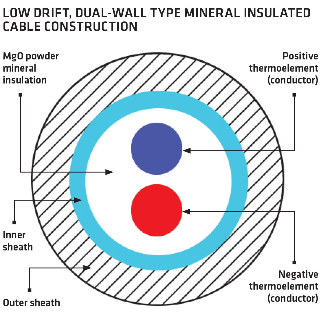
Mineral Insulated Metal Sheathed cable
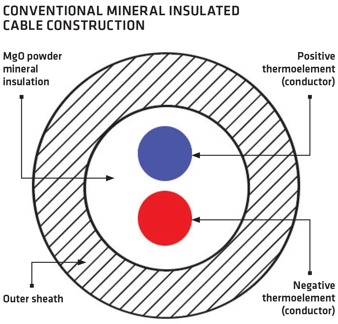
Another type of thermocouple cable is Mineral Insulated Metal Sheathed cable (MIMS). These cables use compacted magnesium oxide (MgO) insulation around the conductors and a metal sheath to form the cable. Sheath materials are most usually stainless steel; Inconel®[4], an alloy of platinum and rhodium; or Nicrobell®[5]. These cables protect the conductors better from certain atmospheres and environments than non-metallic jacketed cables. The application and environment dictate the materials’ selection. Where extremely high temperatures (>2,400°F) are to be measured and where Noble metal thermocouple types R, S, and B are specified, MIMS cable construction is often indicated. Thermocouples made with MIMS cable are one type of nonexpendable thermocouple. There are innovative new low-drift MIMS cable types commercially available that reduce drift, improve accuracy, and may permit a longer useful life. Figure 1 and Figure 2 illustrate cross-sections of conventional MIMS cable (Figure 1), and dual wall low-drift MIMS cable (Figure 2) available from TE Wire & Cable.
Error, Error Limits, and Calibration
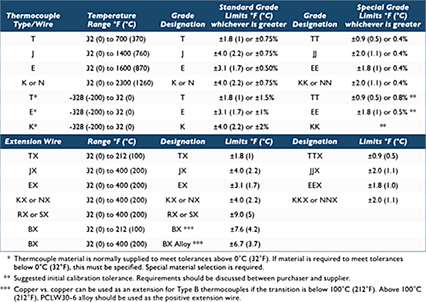
Thermocouple wire may also be specified to have standard accuracy or special accuracy. The level of accuracy is called the limits of error and is defined for each thermocouple type. Standard limits of error for types J, K, and N, for example, are the greater of ±4.0°F or ±0.75 percent; and Special Limits of error for these are the greater of ±2°F or ±0.4°F. Special limits are also call “half limits” or “premium grade” or may be designated as (for example) ‘JJ’ for type J special limits of error. Some manufacturers also offer “quarter limits” or “half special limits” accuracy that would be designated JJJ for type J. (See Table 2)
All thermocouple cable will have some error. Determining the inherent error is the purpose of laboratory calibration, so readings taken can be adjusted for the inherent error in the cable at a given temperature. Depending on the seller, the actual error should be available as a laboratory-calibration report, for any spool of cable over a specified temperature range. This report can be used to calibrate the instruments or recording device.
Calibration Drift
The thermocouple accuracy given by the manufacturer, however, will be for the thermocouple’s first use only. The properties of the alloys begin to change with use, and so the EMF generated and calibration error also change. This phenomenon is called calibration drift and is the reason for limiting the number of uses of thermocouples as prescribed in SAE AMS2750. Calibration drift is most commonly called simply “drift” and is defined in ASTM MNL-12 “Manual on the Use of Thermocouples in Temperature Measurement.”
Thermocouple Usage
All thermocouples have a limited useful life and must not be re-used after a number of uses or number of calendar days after first use, depending on the temperature of the process. SAE AMS2750 is an industry standard that prescribes the limits on thermocouple usage or useful life. Depending on the temperature and process, nonexpendable thermocouples might have a longer prescribed useful life than expendable thermocouples. For example: for a consistent process below 1,200°F, AMS2750 requires that expendable thermocouples must be changed 90 days after first use or after 30 uses, whichever comes first; whereas nonexpendable thermocouples must be changed 90 days after first use or after 270 uses, whichever comes first.
References
- Conductors are used in reference to thermoelements.
- Refrasil is a registered trademark of Hitco Carbon Composites.
- CEFIR is a registered trademark of TE Wire & Cable.
- Iconel is a registered trademark of Huntington Alloys Corporation.
- Nicrobell is a trademark of MICC Ltd.
About the author
Marc Stringer is product manager for OEM & Metallurgy Products with TE Wire & Cable, LLC.


 general practice for CQI-9 and AMS2750E")


