


One of the most common applications of induction heat treatment is the hardening of steels, cast irons, and powder-metallurgy materials, developing an attractive blend of engineering properties [1]. In some applications, it may be desirable to obtain a certain combination of hardness, wear resistance, and contact-fatigue strength at the surface or near-the-surface areas without affecting the core microstructure (e.g., surface hardening of gears and axle shafts). Other cases might require an increase of hardness and strength of the entire cross section of the part, and induction through hardening can help to accomplish the desired industrial characteristics.
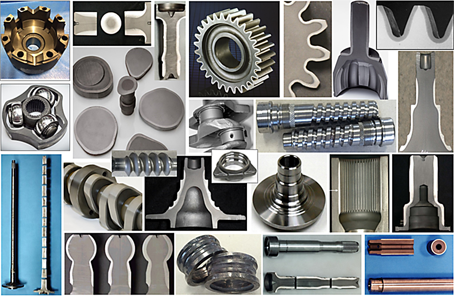
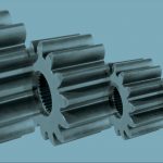
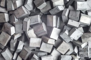
There are thousands of highly successful induction-hardening machines that produce millions of parts supplied to various industry segments. Among the components that routinely undergo induction hardening (IH) are such parts as camshafts, crankshafts, gears, sprockets, transmission shafts, ball studs, pins, toothed racks, wheel spindles, bearing races, fasteners, working tools, track shoes for earth-moving machines — the list is essentially endless. As an example, Figure 1 shows a small array of geometries that are routinely induction hardened.
Several aspects associated with a troubleshooting and prevention of cracking in IH of steel components has already been discussed in the first part of this article [2] published in the September issue of Thermal Processing. This includes the following subjects:
- Impact of a component’s geometry on a part’s susceptibility to cracking upon hardening.
- Steel overheating and grain boundary liquation (incipient melting).
- Factors related to inadequate equipment selection and improper process recipes.
- Initial, transient, and residual stresses and their impact on crack initiation and growth.
- Fishbone diagram of troubleshooting cracking and prevention.
- Case studies.
The second part of this two-part article continues a discussion on this subject, providing additional troubleshooting tips and unveiling remedies to minimize a probability of cracking in industrial practice.
First things first
If cracking has suddenly occurred with equipment that has been running crack-free for some time, then the first questions to ask are “Has everything remained the same until the cracking problem appeared? What was different?” Many times, what might appear to be seemingly insignificant factors such as an installation of a new inductor, refurbished quench assembly, re-tooled fixtures, or newly-replaced quench media might give you an essential clue regarding possible cause(s) of a sudden appearance of cracking. Other questions to ask include:
- Did the workpiece, tooling, or fixture recently have an accidental contact with an inductor or quench device? Check positioning of the workpiece.
- Did your power supply recently encounter an erratic operation, faults, or were limits reached? Check the tightness of all control and power connections, capacitor hardware, transformer tapping hardware, and so on.
- Did the monitoring/control system reveal an inductor ground fault lately or was arcing noted?
- Did a process recipe need to be adjusted or modified?
- Have you or someone else noticed a discoloration or missing pieces of magnetic flux concentrator (if applied)? Make sure that the structural degradation of concentrators did not take place and flux concentrators have not shifted during heating due to ever-present magnetic forces.
- Did your quenchant look or smell differently than normal? Check its concentration, temperature, etc.
- Is there an evidence of excessive dirt accumulation, unexpected discoloration, or an occasional appearance of flame and/or smoke during heating?
Answering those simple questions may reveal vital clues, and remember that the three senses: vision, smell, and hearing can be important assistants.
Factor of steel’s incoming condition
Cracking that occurs during IH often exposes failures taken place during earlier processing stages. This includes the steel defects, as well as defects caused by shaping, machining, trimming, etc. It is imperative to verify the quality of incoming steel. For example, some micro-cracks may be formed during a trimming operation when forging flash is removed. Those micro cracks can advance further during heating and/or quenching. Therefore, validate that the material’s prior microstructure is free of cracks and microcracking did not develop prior to IH.
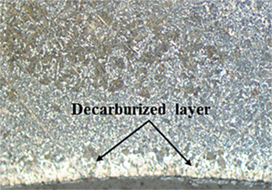
Initially, decarburized steels are another example of a problem that might be associated with the quality of incoming material. Decarburization indicates the loss of surface and near-surface carbon content (carbon depletion) from the steel after being exposed to sufficiently high temperatures in an oxidizing atmosphere, such as air (Figure 2). The depth of the decarburized layer is a complex function of several factors [1]. ]
A considerable amount of decarb is commonly present when dealing with as-hot rolled bar stock, as well as as-forged, annealed, or normalized steels. The presence of decarburized layers at the surface of “green” parts exhibits a significant problem for IH since those layers will remain within the as-quenched structure, worsening strength, wear resistance, fatigue life, impact and bending properties, etc.
Carbon content determines the achievable steel’s hardness level, therefore, a “soft” surface caused by a decarburization can lead to not only localized severe hardness and strength reduction, but it may even reverse the residual stress distribution, forming undesirable localized tensile surface stresses, which in turn can cause delayed cracking or premature failure of components during their service life.
With its short process time, induction hardening itself does not typically produce any measurable amount of decarb. Incoming decarb cannot be repaired during rapid IH under normal processing conditions. Thus, decarburization, as well as some other undesirable conditions resulting from the steel prior processing (e.g., seams, laps, etc.), excessive oxide scale buildup at the surface, intergranular oxidation, and burns should be avoided.
It is not realistic to expect that a certain grade of steel, having the exact chemical composition, will always be supplied. Steel has become a globally sourced commodity, which raises the need for the heat treaters to have a clear understanding of what kind of deviations might be expected when dealing with different suppliers or using certain steel grades in different applications.
Also, due to a variety of factors related to steel making, even different batches of steel of the same grade and produced by the same steel supplier will not have an identical chemical composition. Acceptable ranges are specified and standardized. For example, according to the Heat Treater’s Guide [3], it is not unusual even for plain carbon steels to have a carbon content variation in the range of about 0.05 percent and higher. Extreme variation in carbon content alone can produce a respected deviation in obtainable surface hardness and the ability of the steel to be hardened to a certain depth (hardenability) [1]. If insufficiently small “safety” factors were used in developing IH-process protocols, then this variation may trigger “cracking-non-cracking” outcomes of hardening. Steels with a higher carbon content are often associated with an increased tendency for crack initiation, assuming the rest of the heat-treating conditions remain the same.
Although the percentage of carbon content by far provides the greatest influence on the properties of hardenable steels, there are a number of other chemical elements that, depending on their amount and mutual interactions, can also notably affect the results of hardening. This includes a crack sensitivity and steel brittleness; the extent of which depends on the amount and combination of elements present. Some of these additional chemical elements happen to be in steels as traces or residual impurities contained in the raw materials; others were added during melting for the development of certain conditions during the steelmaking process (e.g., deoxidation, melting specifics, etc.).
Though plain carbon steels are widely used in the industry, there are many industrial applications where their properties are not suitable for meeting certain industrial requirements or a combination of needed and often conflicting engineering properties. This is why an appreciable amount of alloying elements might be purposely added to the steel for developing certain properties. Thus, potential deviations of chemical elements should be taken into consideration during developing process recipes of IH.
An unfavorable combination of alloying elements and residual impurities could promote brittleness and crack sensitivity. For example, in most cases, it is preferable to minimize sulfur and phosphorus residuals. Sulfur reacts with iron, producing hard, brittle iron sulfides (FeS) that have a tendency to become concentrated at grain boundaries and increase the sensitivity to intergranular cracking [1, 2]. FeS in carbon steels is suppressed by the addition of an adequate amount of Mn to form MnS, creating a less brittle microstructure. The amount of Mn should be sufficient to prevent the forming of FeS. “Mn-to-S” ratio of about 5:1 or so is quite commonly specified for carbon steels. Therefore, it is important to make sure that not only an amount of particular elements is within the accepted range, but also their ratios. In addition to sulfur, excessive levels of phosphorus, tin, and copper also can worsen cracking susceptibility in steels.
Thus, the use of lower-than-specified quench temperatures and concentration, as well as higher-than-specified quench flow rates and pressures can initiate cracking with an excessive amount of some residuals, particularly if geometrical stress risers are present. Thus, steel’s composition and quench parameters should be verified if cracking suddenly occurs.
The real-life existence of the hardenability band (having upper and lower hardenability limits) is associated with a permissible, yet extreme, variation of steel’s chemical composition. This means that even for perfectly repeatable heating and quenching cycles, the surface hardness, hardness pattern, as well as formation, distribution, and magnitude of transient and residual stresses could be affected to a certain degree, depending on the steelmaking practice, the raw materials, precise steel composition, and a number of other factors. This makes it beneficial to use H-steels that have a tighter control on hardenability limits compared to steels with a normal composition variation. Unfortunately, not all hardenable steels are available as H-steels.
Regarding the subject of the composition control, it is important to notice an enormously powerful impact of a very small amount of boron (less than 0.005 percent B) on steel hardenability enhancement [3]. However, this beneficial quality of boron may introduce some challenges emphasizing the need of its tight control, because even seemingly very small variations of boron content (e.g., ±0.0005 percent B) might have a measurable impact on steel hardenability and hardness pattern. A similar phenomenon takes place when dealing with plain carbon steels having variable residuals of Mo and Cr. It is important to be aware that, in some cases, an increased hardenability may cause a crack initiation [1].
Steelmaking operations have continuously improved, and the steels produced today will often have a relatively consistent chemistry with a reduced (but not eliminated) composition variation. Therefore, a potential variation of chemical composition should be taken into consideration when developing process protocols or trying to determine a root cause of the sudden appearance of cracking.
It might be beneficial to remember: “If, for some reason, a steel part does not respond to heat treatment in an expected way and cracking develops, then one of the first steps in determining the root cause for such unexpected behavior is to make sure that the steel is sufficiently clean and has the proper chemical composition, specified initial prior microstructure with minimal segregation.”
Hardening shaft-like components
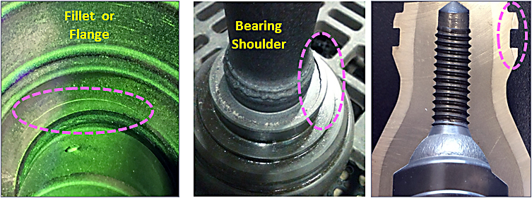
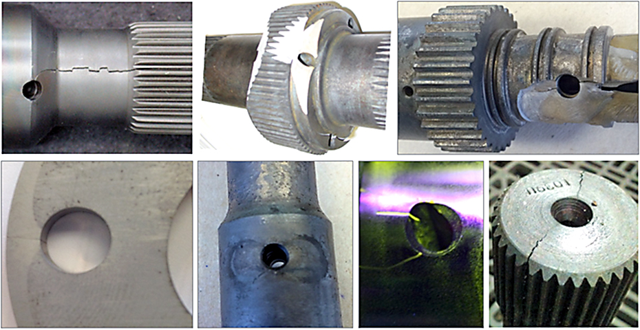
The hardening of flanged shafts, output shafts, planet carriers, yoke shafts, axle shafts, drive shafts, and other shaft-like components represents a sizable market for IH. Certain geometrical features such as flanges, diameter changes, shoulders, grooves, splines, etc. may distort the magnetic field generated by an inductor, causing temperature deviations, a mixture of “hot” and “cold” spots, excessive thermal gradients, undesirable stress states, and grain boundary liquation [1] that may trigger subsequent cracking. As an example, Figure 3 shows several typical fractures that occurred due to an undesirable combination of inappropriate hardening techniques, coil designs, and/or inadequate process protocols.
There are several regions of concern when hardening the flanged shafts. One such area where a circumferential surface fracture may occur is the radius (fillet) between the shaft portion and the flange (Figure 3, left). Coarser initial grains and a deeper case depth increase a probability for cracking. For example, a hot upset flange may exhibit a considerably coarser initial grain structure compared to hot-rolled bar stock of the shaft. The concern of cracking is particularly alarming in applications of through-hardened flanges or when a hardened case depth occupies a substantial portion of the flange thickness. Thus, the reduction of the peak temperatures in the flange and the case depth (if permitted) can help to eliminate crack initiation.
Another area of concern is located in the proximity to a bearing shoulder (Figure 3, center). Sharp shoulders, corners, and large diameter changes can considerably distort the eddy current flow and may produce a measurable temperature surplus forming undesirable microstructures susceptible to a crack development. Those cracks are also typically circumferential. Higher temperatures and deeper hardness case depths in that area increase the likelihood for a surface fracture.
The third region of concern when hardening flanged shafts (e.g., axle shafts) is a shaft’s area adjacent to a flange. Shafts with small flange radii or no radii as well as thin-walled hollow shafts are particularly susceptible for a formation of a crack. Depending upon a hardness pattern, material’s strength, ductility, and toughness, a circumferential fracture may be initiated in the surface (more typical) or subsurface. In other cases, a component can fracture internally in a transverse or longitudinal direction [4]. Internal cracking is more frequently associated with “as-cast” or “as-hot forged” materials or materials with an undesirable grain flow, kink-band formation, excessive presence of inclusions, their unwanted morphologies, composition, distribution, orientation and size, or any other combination of factors that may result in reduced ductility and toughness as well as overlapping of peaks of tensile stresses.
If improperly addressed, such geometrical discontinuities such as machined grooves, slots, undercuts, keyways, snap rings, teeth, etc. can also cause cracking [1, 4, 5]. As an example, Figure 3, right, reveals some local fractures. Heat surpluses and unequal metal expansion/contraction in a combination with excessive quench severity were causes of those fractures. Improved inductor profiling, process recipe, and modified quenching can help to eliminate cracking.
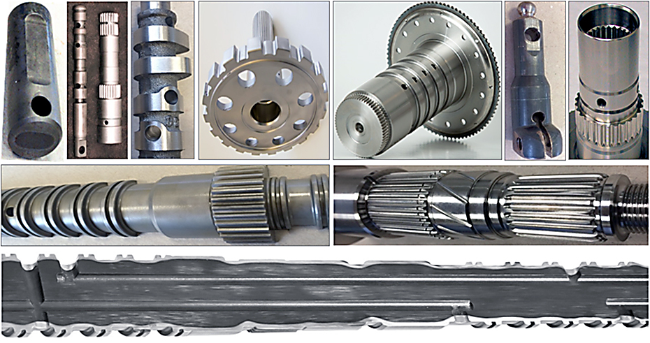
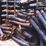
It is not unusual for modern shaft-like components to contain longitudinal (axial) and/or transverse holes (Figure 4) as well as angled or cross holes. Those holes result in an eddy-current flow diversion potentially resulting in an appearance of “hot” spots and, if not properly addressed, crack-initiation sites (Figure 5).
Temperature deviation around the hole may produce a corresponding non-uniform hardness pattern. This is particularly so when dealing with angled holes, where there might be an appreciable variation in heat generation and case depth in obtuse vs. acute angles compared to a straight hole.
It should be noted that temperature surplus alone might not result in crack development. There are other factors that can complement the heat surplus. For example, inappropriate quench intensity and distribution, as well as positioning holes in the proximity to the forging-parting line can increase the propensity to cracking, just to name a few. The repositioning of quench holes further away from the parting line is a step for making parts friendlier to IH. Drilling holes after hardening (if possible) might be another consideration to avoid oil-hole cracking.
Angled holes exhibit considerably different cooling intensities during quenching. With conventionally designed inductors, quenching devices, and recipes, an acute-angle area experiences more severe cooling intensity compared to an obtuse region complementing the heat surplus. This combination makes an acute-angle region to be susceptible to crack initiation.
A complex stress state in the oil-hole vicinity takes place during heating and quenching. There are a number of helpful practical solutions available for heat treaters to enhance the stress state and dramatically reduce or even eliminate the propensity of angled holes for cracking.
Several patented designs were invented during the development of the non-rotational crankshaft hardening technology (CrankPro® hardening machines), allowing selective control of the heat-source distribution in the oil-hole proximity by providing preferable channels for eddy-current flow and intentionally modifying quench profiling.
Experience shows that, in many cases, the proper choice of design parameters (electrical frequency, power density, inductor profiling, etc.) allows one to obtain the required hardened pattern around holes free of cracks. For example, even such complex-shaped parts as a ball bearing cage, which consists of a number of closely located large holes, can be induction hardened instead of using time- and space-consuming carburizing processes. Figure 4, bottom, shows several complex geometry shaft-like components that have been successfully IH, even though, initially, it might seem like an impossible task.
Some parts have multiple closely-positioned holes [4]. The size and orientation of holes may call for a particular induction-hardening technique. As a general rule, if multiple holes are positioned longitudinally, then a single-shot inductor might be a preferred choice compared to scan hardening. On the other hand, if holes are positioned circumferentially, then the use of scan inductors might be more appropriate compared to a single-shot hardening.
Space does not permit a detailed discussion on electromagnetic and heat-transfer subtleties, eddy-current flow in the oil-hole vicinity, an impact of chamfering characteristics, and a selection of process parameters to minimize the probability of cracking. These and other subjects are discussed in [1, 4, 7].
Prevention of cracking in camshaft hardening
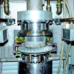
Electromagnetic induction is a popular method for heat treating a variety of automotive components including camshafts. Camshafts belong to a group of irregularly-shaped parts consisting of several sets of cam lobes and bearings. The number of lobes, their size, profile, positioning, and orientation depend upon the camshaft type and engine specifics and can vary to great extent [8].
In the past, IH of camshafts commonly require their rotation. Unfortunately, because the nose of the cam lobe has a closer electromagnetic coupling with the coil, this approach was associated with noticeably deeper case depths in the nose compared to its base circle (the heel). As an example, Figure 6, left, illustrates a typical variation in electromagnetic coupling between the coil inside diameter (coil ID) and different regions of the cam lobe. Deeper case depths are associated with reaching higher temperatures.
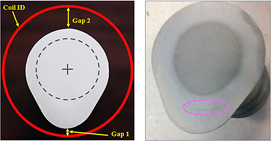
An attempt to provide a minimum required hardness case depth in the poorly coupled base circle/heel region may result in an overheating of the nose that could not only worsen the camshaft’s characteristics including its straightness, but it can also produce an undesirable stress state, severe grain coarsening, and incipient melting, potentially causing surface or subsurface cracking (Figure 6, right). When IH low toughness materials (e.g., high carbon steels, cast irons, etc.), even seemingly insignificant increases in the hardness case depths may be sufficient to initiate cracking.
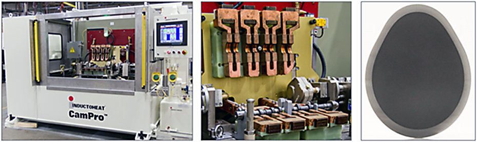
In order to dramatically minimize a probability of cracking, a non-rotational SHarP-C™ technology has been effective for contour hardening of cam lobes. Figure 7, left, shows a CamPro® machine that uses SHarP-C™ technology, a multi-lobe inductor design (Figure 7, center), and a hardness pattern (Figure 7, right). Experience shows that a CamPro® machine can not only exhibit reduced energy consumption, but it also can produce much straighter camshafts. Some users of CamPro® machines have reported almost undetectable camshaft distortion, an elimination of the entire straightening operation. and measurable scrap reduction [8].
Common remedies to minimize the probability of cracking
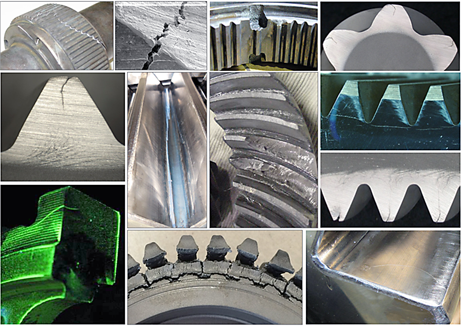
The existence of an endless variety of components that are routinely induction hardened has educated us with various remedies to minimize a probability of cracking. If cracking has occurred, a thorough investigation should be conducted applying principles and general practices of failure analysis [5], and it should take into consideration subtleties of a particular IH application. It is important to remember that a cracking problem is often application-specific. Therefore, the collection of reliable background data and heat-treat history is imperative.
Certain part geometries and materials grades might be prone for a particular failure mode. As an example, Figure 8 shows an appearance of a variety of cracks when heat treating gears and gear-like components. Even a brief look at Figure 8 reveals a complexity of factors, an ambiguous nature of cracking and its root cause(s) related to just gear-like parts.
Over the years, the industry has developed a number of general remedies that might help to eliminate cracking issues in IH. Some of those remedies are listed below (when applying remedies associated with modification of a process recipe, always make sure that hardness levels and patterns are within the required “min-max” range and discuss your actions with the OEM):
- Determine when the cracking occurred (for example, during heating or quenching, before or after tempering or perhaps it is a post heat-treating fracture that appeared after grinding/straightening).
- Proper metallographic examination [5] should be conducted assessing crack morphology, a possible relationship with a microstructure, determining the fracture mode and the most probable cause of fracture.
- Verify anticipated prior microstructure and chemical composition of an incoming material. Its cleanliness, degree of heterogeneity/segregation, grain coarseness, presence of imperfections (e.g., laps, seams), as well as the type of non-metallic inclusions, their composition, shape, size, and distribution (ASTM E45 or ISO 4967). Non-metallic inclusions may or may not affect cracking — it depends. Remember that steel cleanliness affects not only quality of end-use products (in particular fatigue life of highly stressed transmission components) but it may also affect cracking sensitivity [1]. If the steel’s initial structure is appreciably different than expected, then this issue must be addressed to your steel supplier. Appropriate measures should be taken in improving a friendliness of a material’s initial structure prior to IH. For example, in order to refine the structure of hot-forged parts (e.g., hot upset forged flanges or splines); it might be beneficial to normalize it prior to machining and IH.
- Validate that the microstructure of a “green” part is free of cracks and microcracking developed prior to induction hardening.
- Make sure that the workpiece has an anticipated geometry, and it is properly positioned during heating and quenching. A part’s unspecified positioning, self-re-allocation, and tilting during IH, as well as its slippage and excessive wobbling during rotation should be avoided. Thin, elongated components should not fit snugly, allowing expected part growth during heat treating.
- Verify that adequate inductor and process recipe have been used. Have any abnormal electrical limits, ground faults, arcing, or other parameters been detected by process monitoring devices?
- Make sure that spray quench orifices are not plugged, resulting in unspecified quench nonuniformity. Verify that the quenchant has the required conditions and there is no obstruction for the spray quench to reach the part’s surface.
- Do not compromise, instead use appropriate induction equipment that would allow true optimization of a process recipe by having a capability to not only adjust power and scan rate/heat time, but electrical frequency as well.
- Reduce temperature of austenitization by applying slightly lower power (< 1-3%).
- Apply quench delay (0.25-0.75 sec).
- Increase quenchant temperature approx. 2-3°F.
- Increase quenchant concentration (approx. 1-3%).
- If specified, tempering (oven or induction, whatever is specified) should be done as soon as possible. Long delays between hardening and tempering may result in the delayed cracking, which could be caused by several factors. It is particularly beneficial to position the tempering operation immediately after the hardening machine or at least in the same building when dealing with low-toughness materials and high-hardness levels.
- Shorten duration of the quench cycle and apply some self-tempering (if applicable). If possible, apply a combination of self-tempering and multi-pulse induction tempering.
- Increase time of tempering (if applied), using low values of tempering power and/or frequency or applying IFP technology or multiple heat-soak cycles at low-power levels and reduced frequencies.
- Increase the time prior to the final cool-down stage (time between the end of tempering and the beginning of the eventual cooling down for the part’s safe handling).
- Some cracks that occur very infrequently are so rare, they may be considered as a statistical event. It is much easier to determine the root cause of cracking if it can be turned “on” and “off” by modifying the process parameters.
- It is difficult to over-emphasize that if a fracture occurs, it is imperative to determine after which process stage it appears (after heating, quenching, part transportation to tempering, after tempering or post heat-treat operations such as grinding or part identification). Final grinding, straightening, and part identification can have a noticeable impact on both: residual stress distribution as well as cracking. Abusive grinding is known to be responsible for altering as-hardened microstructures and the residual stress state and could promote notch sensitivity and fractures. Stamping or laser carving the identification number into the part should be done outside of the heat-treat areas. The same rule should be applied for electro-etching and other part-identification techniques.
It is worthwhile to repeat that if an attempt to eliminate cracking by any of the previously described actions isw used to modify a process recipe, it will be necessary to make certain that the full customers’ heat-treat specifications are still met.
Conclusion
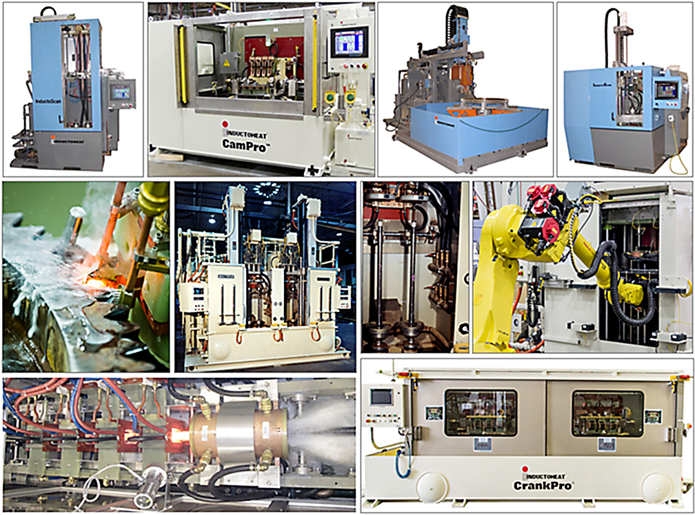
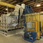
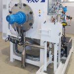
IH is a proven technology, and many thousands of induction machines are in service worldwide. The popularity of this technology continues to grow, and inventions and innovations are appearing quite regularly. Induction equipment is energy efficient, flexible, reliable, robust, and environmentally friendly, producing components with enhanced metallurgical quality. As an example, Figure 9 shows equipment that has already reached undisputable standards in modern heat-treat industry.
Unfortunately, as with any process, heat-treat professionals occasionally may encounter some cracking issues. Each part has its own “personality” that affects the outcome of heat treatment. Even a cursory look at the “fishbone” diagram of cracking [2] unveils the intricacy and challenges in determining the root cause and the consequential factors associated with cracking.
In real-world needs, manufacturers of IH equipment should have the experience and analysis necessary to help heat-treat practitioners with specific problems. Understanding a broad spectrum of factors associated with various failure modes is an important step in designing new products and developing crack-free processes. Mutual cooperation of designers and equipment manufacturers are vital for success.
Finally, we would like to share the statement that is popular among heat treat professionals: “In the beginning there is PRICE, at the end there is COST. The difference is QUALITY. This quality ensures the ability of heat-treat professionals to avoid unpleasant surprises by using past experience, engineering expertise, computer modeling capability, and awareness of the latest advances in theoretical knowledge.”
References
- V.Rudnev, D.Loveless, R.Cook, Handbook of Induction Heating, 2nd edition, CRC Press, 2017.
- G.Doyon, V.Rudnev, R.Minnick, T.Boussie, Troubleshooting and Prevention of Cracking in Induction Hardening of Steels: Lessons Learned. Part 1, Thermal Processing, September, 2019.
- Heat Treater’s Guide: Practices and Procedures for Irons and Steels, ASM International, 1995.
- V.Rudnev, Simple Solutions for Typical Induction Heating Challenges, ASM Webinar, January 24, 2019.
- ASM Handbook Volume 11: Failure Analysis and Prevention, ASM International, 1998
- V.Rudnev, Induction Heating: Q&A, Professor Induction series, Heat Treating Progress, August, 2009, p.9-11.
- V. Rudnev, R. Cook, J. LaMonte, Induction heat treating: Keyways and holes, Metal Heat Treating, March–April 1996, pp. 83–86.
- G.Doyon, V.Rudnev, J.Maher, R.Minnick, G.Desmier, Elimination of straightening operation in induction hardening of automotive camshafts, Int. J. Microstructure and Materials Properties, Inderscience Ltd., Vol. 11, Nos. 1/2, 2016, p.119-133.


 general practice for CQI-9 and AMS2750E")


