


Gears are the most important components for transmissions. In many situations, the size of a transmission design needs to be reduced without decreasing power density. One of the most effective methods is to reduce the gear size while keeping the same output torque capacity. In general, gears used in heavy load conditions are made of steel, and gear tooth residual surface stresses are critical to the fatigue performance. Compressive residual stresses in the critical region of a gear improve its fatigue performance.
However, many steel gears are not processed to obtain residual surface compression, or the benefit of residual compression is not considered in the gear and transmission design. In this article, virtual computer models using DANTE® software are used to assist with achieving gear size reduction by including steel grade hardenability and heat treatment in the design process. In this study, the original gear is made of AISI 4340 and oil quenched and tempered. The gear with reduced size is made of AISI 8620. Carburization and oil quenching are used to introduce residual compression to the root fillet of the gear tooth; this is the most critical region concerning high cycle bending fatigue performance. By taking advantage of the residual compression at the root fillet, the gear with reduced size can deliver the same torque load while having better bending fatigue performance relative to the original gear.
Gears are the most important components in transmission and actuator designs. In many cases, the size of a transmission or an actuator needs to be reduced for minimum weight or dimensional advantages without losing its strength to deliver torque load. To accomplish this goal, the whole process from design and manufacturing should be considered. A possible solution can be selecting stronger material, or changing from spur gear to helical bevel gear shape. Steel gears are heat treated to increase its hardness and strength for improved performance. By effectively selecting and designing the heat treatment process, compressive residual stresses can be introduced to the gear surface to benefit the high cycle fatigue performance [1-3]. A combination of carburization and quench hardening has proven to generate compressive residual stresses to the gear surface due to delayed martensitic transformation with volume expansion. The compressive residual stresses will reduce the magnitude of the actual stresses generated in the critical location of gears under the service load. The computer modeling of carburization and quench hardening process is more mature than ever, which can be accurately used to troubleshooting and design the heat treatment processes for steel parts [4-10]. In this article, heat treatment process modeling using DANTE, will be implemented to select material, and design the heat treatment process for a gear component for reduced size while maintaining the strength to deliver the original torque load.
Descriptions of Gear Geometry, FEA Model, and Problem Statement
Geometry Description
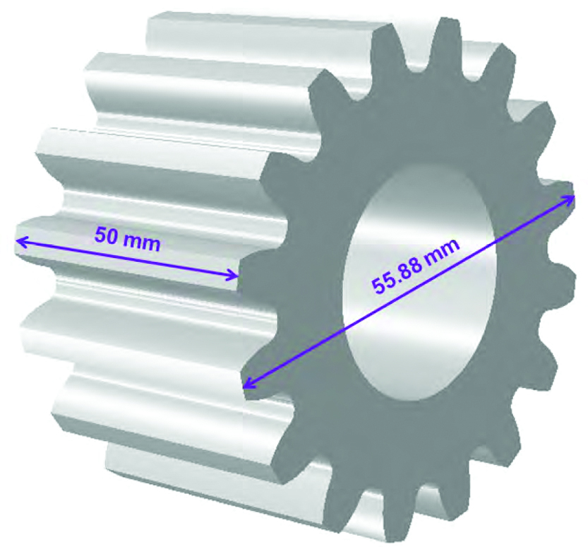
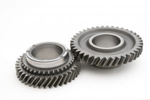
A spur gear made of AISI 4340 is selected for this study, and a CAD model is shown in Figure 1. The outer diameter of the gear is 55.88 mm, its inner diameter is 25.4 mm, its root diameter is 44.45 mm, and its thickness is 50 mm. The gear has a total of 16 straight teeth. Quench hardening in oil is used as part of the specification for hardness and strength requirements.
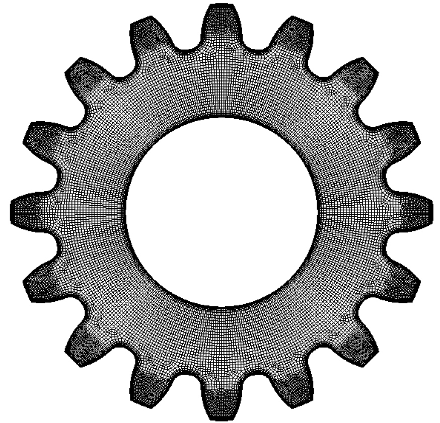
For this specific gear, the failure at the gear root fillet during high cycle bending fatigue test is the main concern. Previous studies have shown that the tangential stress around the root fillet under fatigue load is the main driver of the fatigue crack initiation and propagation. For this gear geometry, the contribution of the temperature and phase transformation gradient in the axial direction during quenching to the tangential stress generated around the root fillet is negligible relative to those in the radial direction. Therefore, one midplane cross section of this gear in the axial direction is used for the modeling study, and a plane strain finite element meshing is developed to model the gear responses during heat treatment and loading, as shown in Figure 2. The total number of nodes in the model is 30,160, and the total number of elements is 28,544. The 4-node linear element is used for the analyses. Fine elements are used in both the tooth surface and the bore surface to effectively catch the gradients of carbon, temperature and stresses during the heat treatment processes.
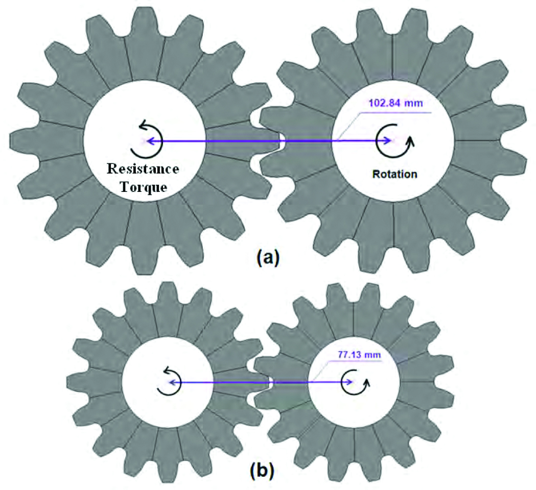
High cycle bending fatigue performance is used as the main criterion to evaluate the strength of the gear. In general, the driven and driver gears have different designs, including the size, number of teeth, and tooth profile, etc. In this article, the main focus is to investigate the effect of the material selection, heat treatment process and residual stresses on the fatigue performance, and how to take advantage of the compressive residual stresses to reduce the gear size. To simplify this study, it is assumed the driver and the driven gears have the same size, and the input torque and the output torque (resistance) are the same. The setup of the gear pair under rotational bending load is shown in Figure 3(a) for the original gear size design. The centerline distance is 102.84 mm between the gear pair. The gear on the left is the driven gear with a resistance
torque load of 3,287.5 N·m applied in the direction as shown. A rotational displacement is applied to the gear on the right. The input torque is 3,287.5 N·m, which is same as the resistance torque applied to the driven gear.
The original gear is made of AISI 4340 with oil quench hardening. DANTE was used to model the oil quench process, and the magnitude of the predicted residual stresses is negligible. In this study, it is assumed that the residual stress from heat treatment of the original size gear made of AISI 4340 is zero. To reduce the gear size, a combination of carburization and oil quench is proposed to introduce compressive residual stresses to the gear surface for improved bending fatigue performance. The selected material is the carburization grade AISI 8620, and the proposed gear size reduction is shown in Figure 3(b), with 25% reduction in the X-Y plane while keeping the same axial dimension. The OD of the reduced size gear is 41.91 mm, the ID is 19.07 mm, the root diameter is 33.34 mm, and the thickness is 50 mm. The volume or mass of the reduced size gear is 56.25% relative to the original size gear. During rotational bending fatigue test, the centerline distance between the gear pair is reduced proportionally to 77.13 mm. To simply this study, the same finite element meshing is used for the reduced size gear by reducing the element size by 25% proportionally.
Modeling of Carburization and Quench
Hardening Processes
The reduced size gear is gas carburized, followed by oil quench and low temperature tempering. The whole gear surface is carburized, and the carburization cycle is briefly described below:
• Temperature: 1697° F (925°C).
• Time period: 8 hours.
• Carbon potential: 0.8%.
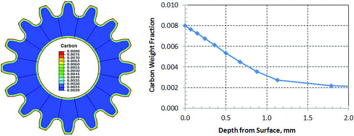
The predicted carbon distribution contour is shown in Figure 4(a), and the contour legend is the weight fraction of carbon. A straight line is selected at the root fillet of the gear to plot the carbon content in terms of depth from the tooth surface, and the result is shown in Figure 4(b). The predicted effective case depth (ECD) is 0.75 mm with the assumption 0.4 wt.% carbon being the threshold of ECD definition.
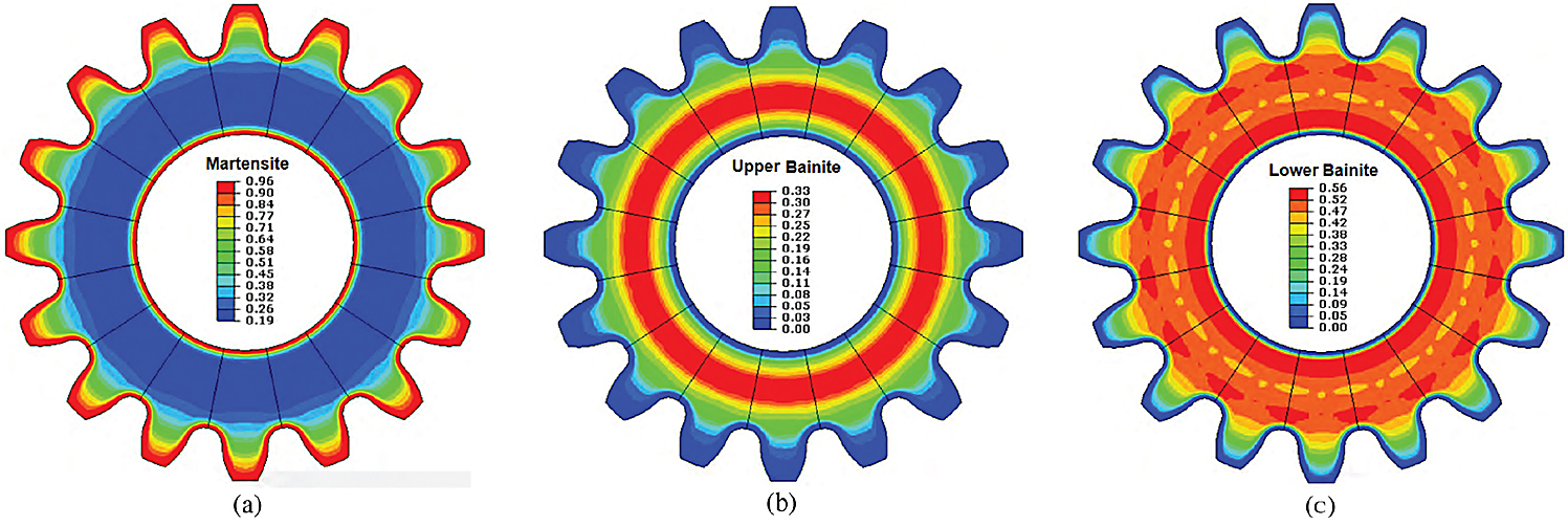
After carburization, the gear is cooled to 1607°F (875°C) in furnace. This process is often used in practice for reduced distortion from quenching. Once the gear reaches the equilibrium temperature of 1607°F (875° C), it is taken out of the furnace for oil quench. The transfer time from the furnace to the quench tank is 12 seconds. The oil temperature is 149° F (65°C). After quenching, the gear is cleaned and furnace tempered for one (1) hour at 347°F (175°C). The predicted volume fractions for different phases are shown in Figure 5. The gear tooth is mainly martensite. The core has about 20% martensite, 33% upper bainite, and 47% lower bainite. About 10% of retained austenite is predicted on the carburized surface of the as-quenched gear. The amount of predicted ferrite and pearlite is negligible.
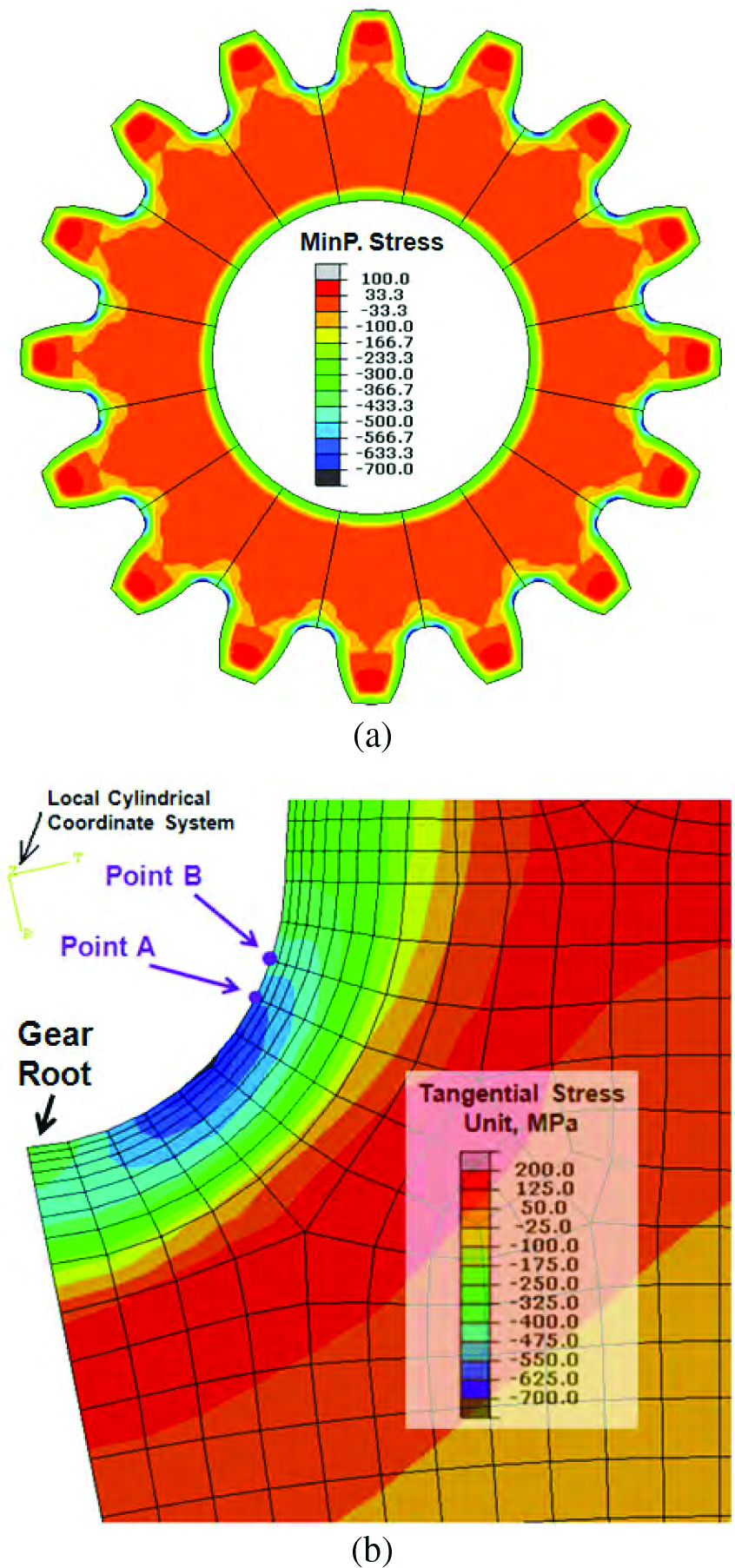
With the combination of carburization and oil quenching, compressive residual stresses are generated in the surface of the gear. The predicted minimum principal stress is shown in Figure 6(a). Both the bore surface and the tooth surface are under compression due to the delayed martensitic transformation in the high carbon case. The root fillet has higher magnitude of compression comparing to that at the tooth flank region, which is due to the stress concentration of the geometry effect during quenching.
The directions of the minimum principal stresses vary at different locations of the gear. It has been validated from the modeling results that the minimum principal residual stress at the root fillet is in the tangential direction after quench hardening. The tangential stress also directly relates to the fatigue crack initiation and propagation around the root fillet. A local cylindrical coordinate system is defined to plot the tangential stresses in the root fillet of the gear, as shown in Figure 6(b). The center of the cylindrical coordinate system matches the center of the gear fillet. The highest residual compression around the fillet is about 700 MPa, and its location is close to the center of the root. Using this local coordinate system, the stress contour close to the root fillet represents the tangential stress, but the stresses in this direction are meaningless for locations far away from the fillet.
Modeling Gear Stresses under Rotational Bending Torque Load for Fatigue Test
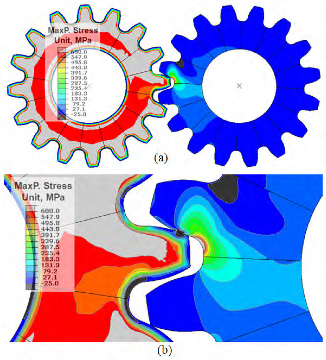
Using the rotational bending fatigue test setup shown in Figure 3, the stresses in the gear under a constant torque load of 3287.5 N·m is modeled. For all the rotational bending fatigue load models in this article, it is assumed that all the gears are under elastic deformation, and linear elastic material properties are used. The maximum principal stress distribution contour of the original size gear pair is shown in Figure 7.
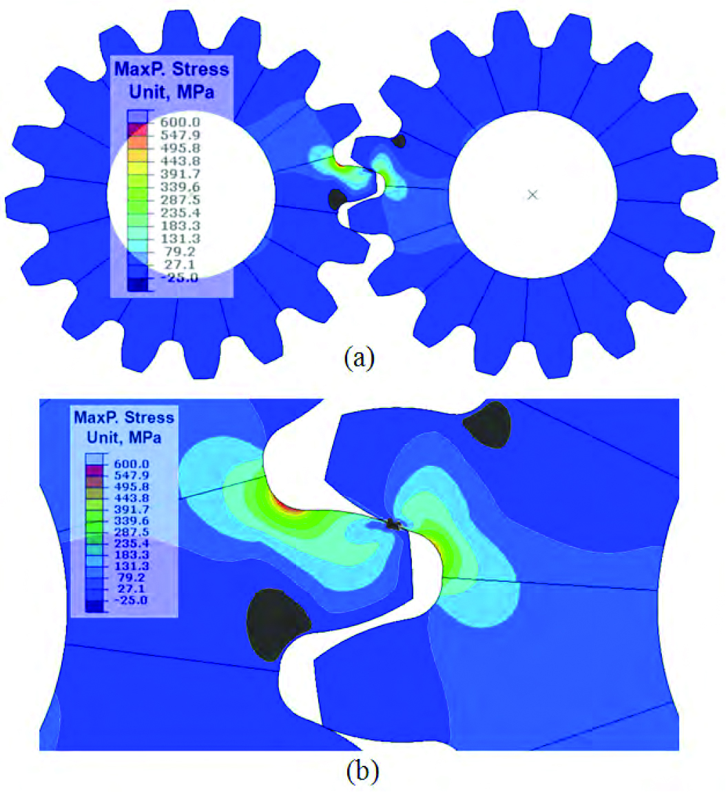
As shown in Figure 7(b), the highest maximum principal stress is at the root fillet, and its direction is along the tangential direction of the fillet. During the rotational bending process, the two gears may contact between one pair of teeth or two pairs of teeth. With two pairs of teeth contacting between the two gears, the stress generated at the root fillet is lower. The bending stress at the root fillet also changes with the contact position. The highest bending stress at the root fillet is generated when only one pair of teeth contacting at the longest arm from the root fillet. The stress contour of the snapshot shown in Figure 7 has the highest tensile stress at the root fillet of the left gear.
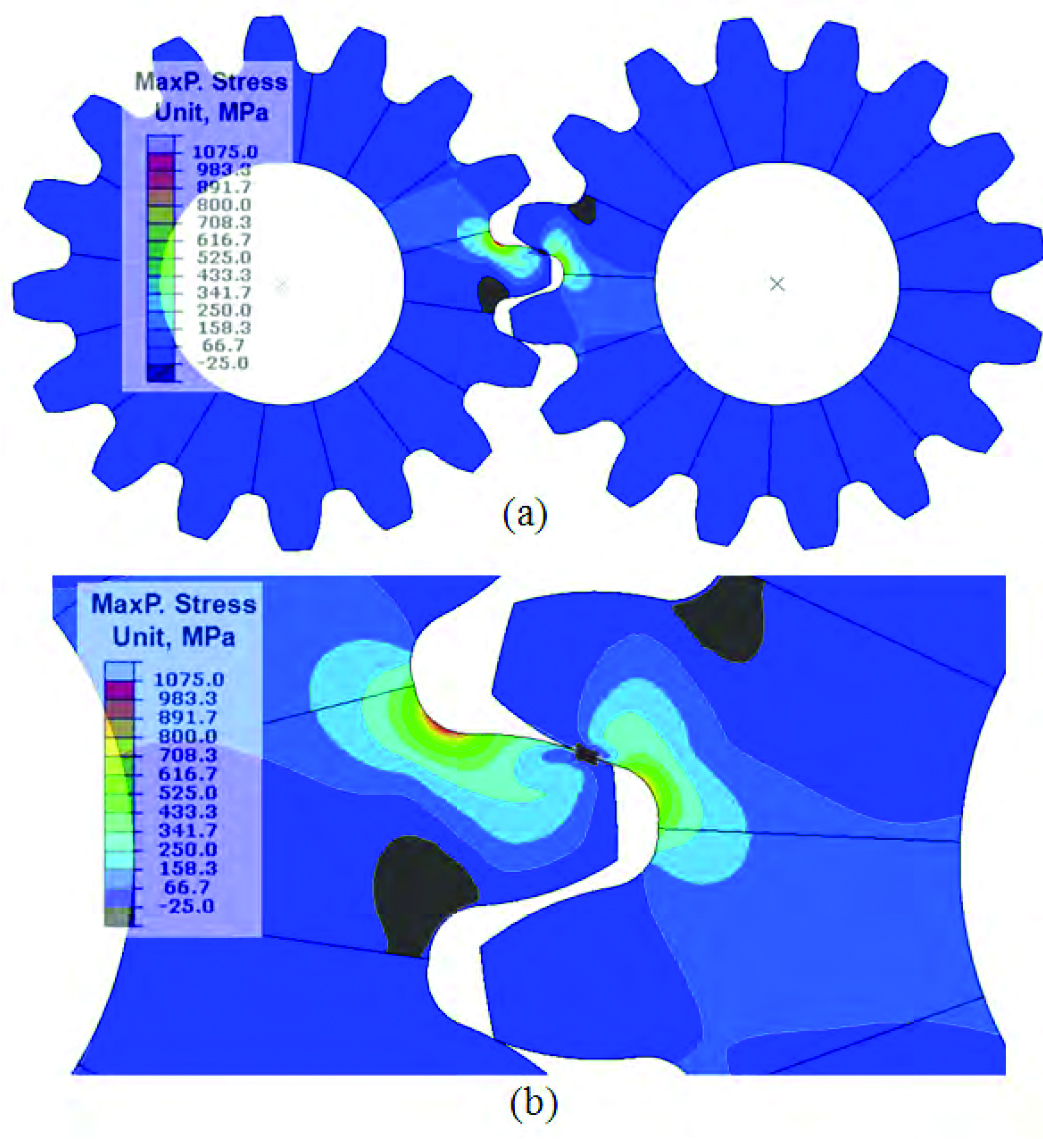
By reducing the gear size by 25% in the X-Y plane, the bending strength of the gear is decreased. Under the same torque load of 3,287.5 N·m, the generated tensile stress magnitude at the root fillet is much higher than that of the original size gear without taking advantage of the compressive residual stresses introduced from the heat treatment process. Figure 8 shows a snapshot of maximum principal stress contour with the highest bending stress generated at the root fillet, which is 1075 MPa comparing to 600 MPa for the original size gear.
The compressive residual stresses introduced from the heat treatment process can significantly benefit the high cycle bending fatigue strength of the gear. In this study, the residual stresses from the carburization at quench hardening process shown in Figure 6 are imported to the rotational bending fatigue model. Under the same constant torque load of 3,287.5 N·m, the predicted maximum principal stress contour is shown in Figure 9. To simplify the model, the residual stresses from heat treatment are imported to the left gear only. The stress distribution in the right gear is not considered. The highest stress generated at the surface of the root fillet is slightly below 600 MPa, which is significantly lower than the value of 1075 MPa shown in Figure 8 without considering the residual stresses. From the contour plots shown in Figure 9, the highest stress is under the surface. It has shown that the high cycle fatigue cracks initiate on the surface even the highest tensile stress point is under the surface, which is because the surface is rich with crack initiation sites. Of course, the crack can initiate under the surface if the steel is not clean.
Discussions
By selecting AISI 8620 as the gear material, the combination of carburization and oil quench introduces compressive residual stresses to the gear surface, which will significantly reduce the magnitude of the actual stresses around the root fillet under the torsional bending load. Using the local cylindrical coordinate system described in Figure 6(b), the predicted actual stresses in the tangential direction of the root fillet under the same torsional load of 3,287.5 N·m are compared in this section. As shown in Figures from 7 to 9, three cases are covered, and their conditions are described below:
• Case 1: Original gear size made of AISI 4340 without the residual stresses from heat treatment
• Case 2: Reduced gear size made of AISI 8620 with the residual stresses from carburization and oil quench
• Case 3: Reduced gear size made of AISI 4340 without the residual stresses from heat treatment
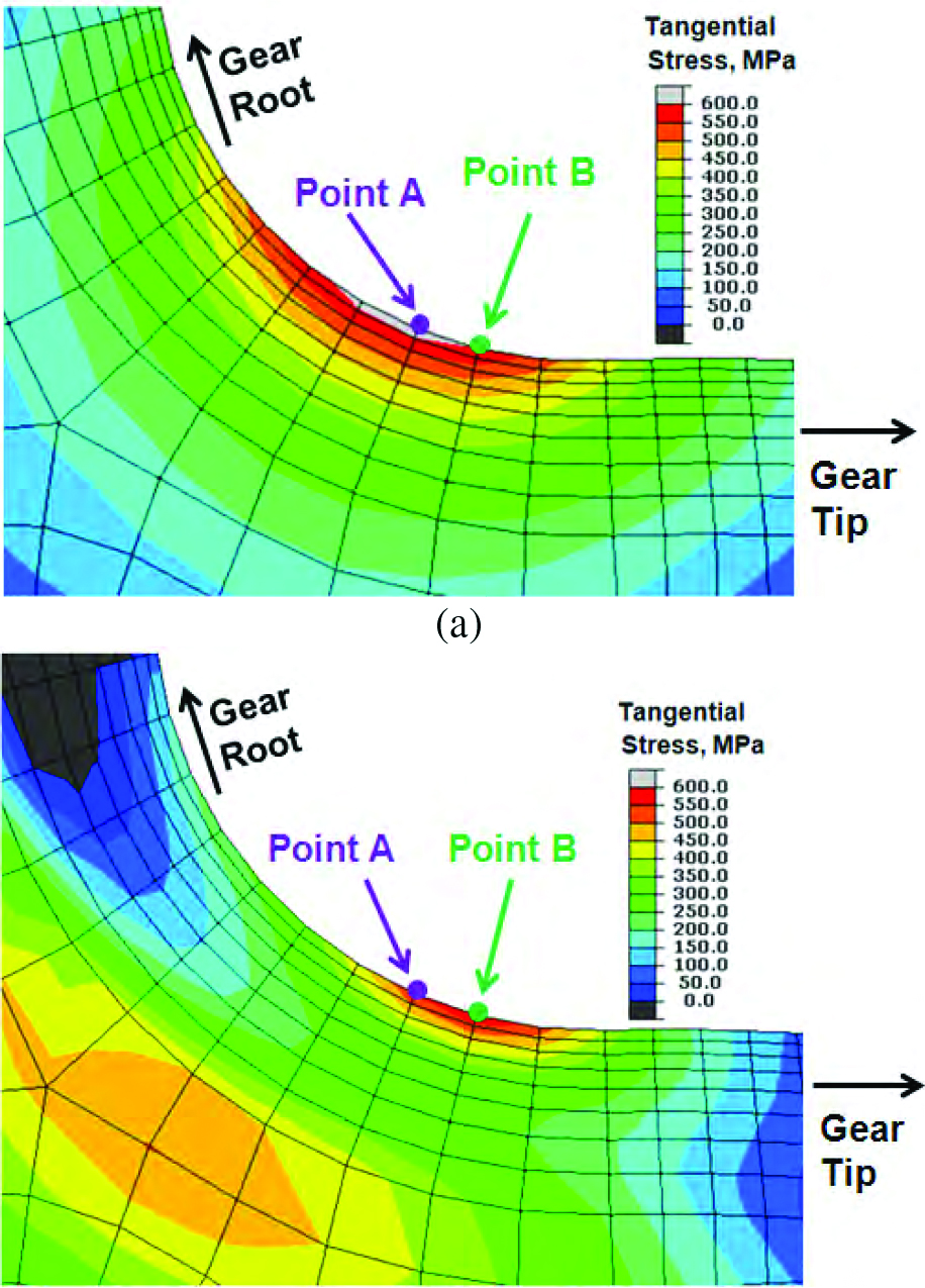
For case 1, the highest stress around the root fillet is about 625 MPa, locating at point A. For case 2, the highest stress is reduced to 600 MPa, and its location, point B, as shown in Figure 10, moves slightly from the root to the gear tip. This phenomenon has been observed that the crack initiation location moves toward the gear tip during single tooth bending fatigue tests of gears [11-12], and the direct cause is due to the profile of the compressive residual stress distribution around the root fillet. A shown in Figure 6(b), the compressive residual stress around the root fillet is not uniform, and the location of the highest point towards the root from the point A. The location of the highest residual compression point is highly dependent on the gear geometry and the cooling rate during quenching. The combination of the residual stresses and the applied stresses is shown in Figure 10(b). Based on the logic described above, the benefit of compressive residual stresses to the fatigue performance can be further improved by optimizing the gear geometry and the heat treatment process, so the highest applied tensile stress location matches the highest compressive residual stress location after heat treatment.
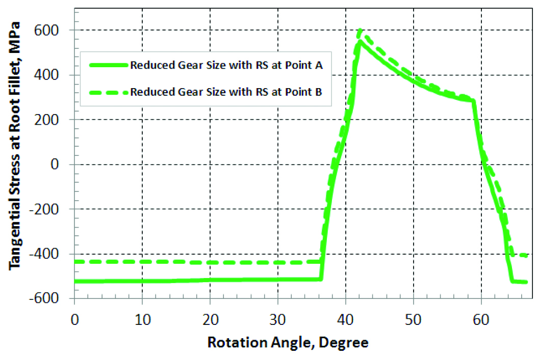
During the rotational bending test of the reduced size gear pair, the history of the tangential stresses at points A and B are plotted in Figure 11, with considering residual stresses from carburization and oil quench processes. Figure 10(b) is the snapshot of the stress contour when the tangential stress at the fillet reaches the highest magnitude, as shown by the peak of the dashed curve (point B) shown in Figure 11.
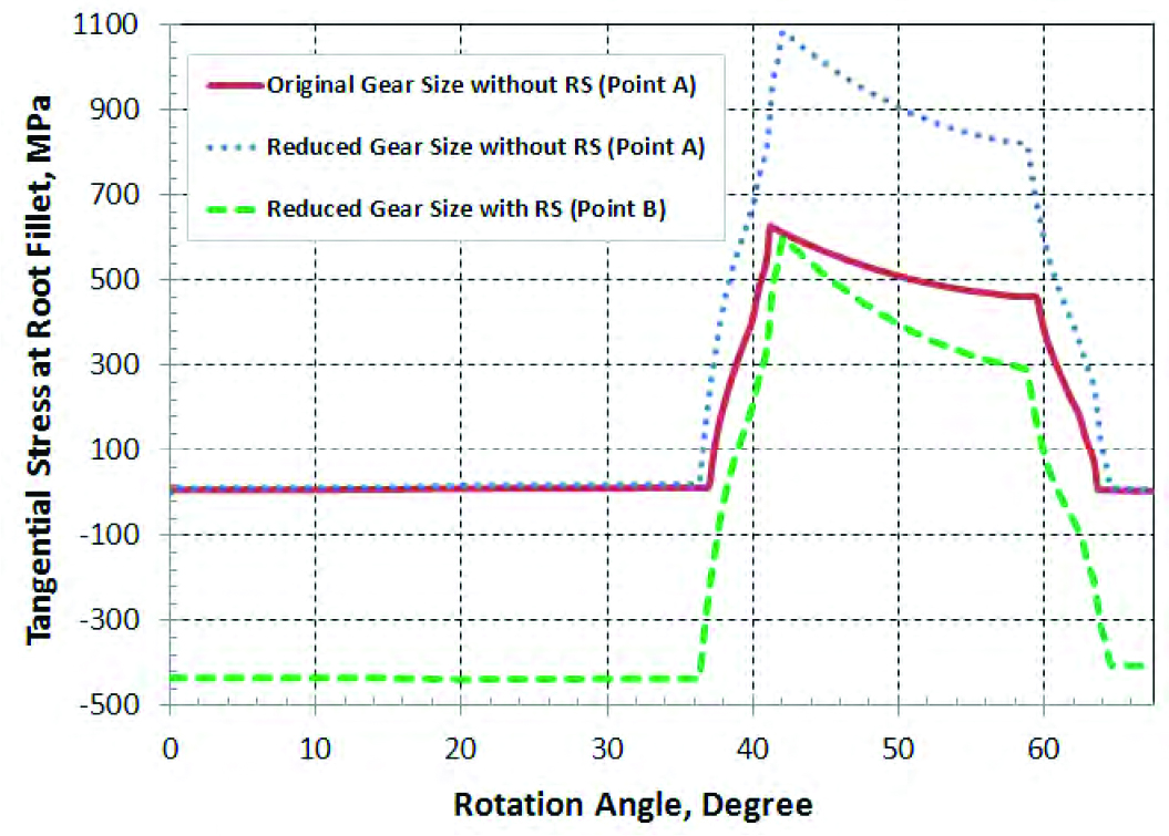
During rotational bending, the history plot of the tangential stresses at the most critical points of the root fillet are compared for the three cases. It is noted that either point A or point B will be used depending on which location has the highest actual stress under load. The peak stress is considered as the main driver of the bending fatigue failure. The comparison shows the significant effect of compressive surface residual stresses on the bending fatigue performance (Figure 12).
Conclusions
The selection of gear material and heat treatment process is critical to its bending fatigue performance. By a combination of carburization and oil quench of gears made of carburized steel grade, compressive residual stresses are generated in the surface of the hardened case. This compressive residual stresses can significantly benefit the high cycle bending fatigue performance of the gears. This concept has been validated by both modeling and experiments. In this study, this concept is further applied to reduce the gear size without reducing its capability of carrying torque load. The case studies in this article have shown that a mass or volume reduction by 43.75% can be compensated by taking advantage of the compressive residual stresses generated from well selected heat treatment processes. The material selection is also critical, and clean material is preferred to reduce the potential crack initiation site under the hardened case, where residual tension exists to balance the surface compression.
References
- Aronov, M.A., Kobasko, N.I., Powell, J.A., Wallace, J.F., and Schwam, D., “Practical Application of the Intensive Quenching Technology for Steel Parts,” Industrial Heating, April 1999, pp. 59-63.
- Banka, A., Franklin, J., Li, Z., Ferguson, B.L., and Aronov, M., “Applying CFD to Characterize Gear Response during Intensive Quenching Process”, Proceedings of the 24th ASM Heat Treating Society Conference, September 17-19, 2007, pp. 147-155.
- Lohe, D., Lang, K.H., and Vohringer, O., “Residual Stresses and Fatigue Behavior”, Handbook of Residual Stress and Deformation of Steel, ASM International, 2002, pp. 27-53.
- Ferguson, B., and Dowling, W., “Predictive Model and Methodology for Heat Treatment Distortion”, NCMS Report #0383RE97, 1997.


 general practice for CQI-9 and AMS2750E")


