


Low pressure carburization (LPC) processes are becoming more widespread throughout industry due to the reduced cycle times and the control over the carbon profile through the case of the carburized component. Unlike gas carburization, which uses a constant carbon potential to maintain the available carbon on the part surface at a specific value, LPC uses boost and diffuse steps. A boost step involves the temporary addition to the furnace of a carbon-carrying gas, usually acetylene, to increase the surface carbon to the saturation limit of austenite. If not properly controlled, the carbon available for diffusion can well exceed the saturation limit, creating unfavorable carburizing conditions.
After a requisite amount of time has passed — generally one to several minutes — the carbon-carrying gas is evacuated from the chamber. The carbon that was deposited on the surface during the boost step is then allowed to diffuse into the part, reducing the surface carbon. These two steps are then repeated until the required case depth and carbon profile are achieved.
Aerospace challenges
For steel alloys that do not contain a significant amount of strong carbide forming elements, this process can be relatively easy to control. However, with the advent of high-strength steels for the aerospace industry, most of which contain substantial amounts of strong carbide-forming elements such as chromium, molybdenum, and vanadium, the LPC process can be extremely challenging to control. These elements bond with the carbon deposited on the surface to form primary carbides, which, if not properly dissolved, can damage fatigue performance. Long boost times, as well as very short diffuse times, can lead to the thermodynamic stabilization of these primary carbides.
While Fick’s Second Law describes the diffusion of carbon through a low-alloy steel with reasonable accuracy, the same is not true of medium- and high-alloy steels. This is due to the presence of primary carbides forming and dissolving during the LPC process. When the boost step is occurring, the primary carbides take carbon away from the austenite solution, allowing more carbon to enter the solid solution from the surface. During the diffuse step, as the carbon that is in solid solution diffuses into the part effectively reducing the carbon in austenite, the primary carbides can dissolve to provide more carbon to the solid-state solution. If the primary carbides are not allowed to fully dissolve or shrink to a significantly small amount before the next boost step begins, they will continue to grow.
Primary carbide formation and dissolution
In order to properly predict the carbon profile of medium- and high-alloy steels, the primary carbide formation and dissolution must be considered. The heat-treatment simulation software DANTE has this capability and was used to fit the diffusivity and primary carbide kinetics of Ferrium C64 steel alloy from LPC experiments.
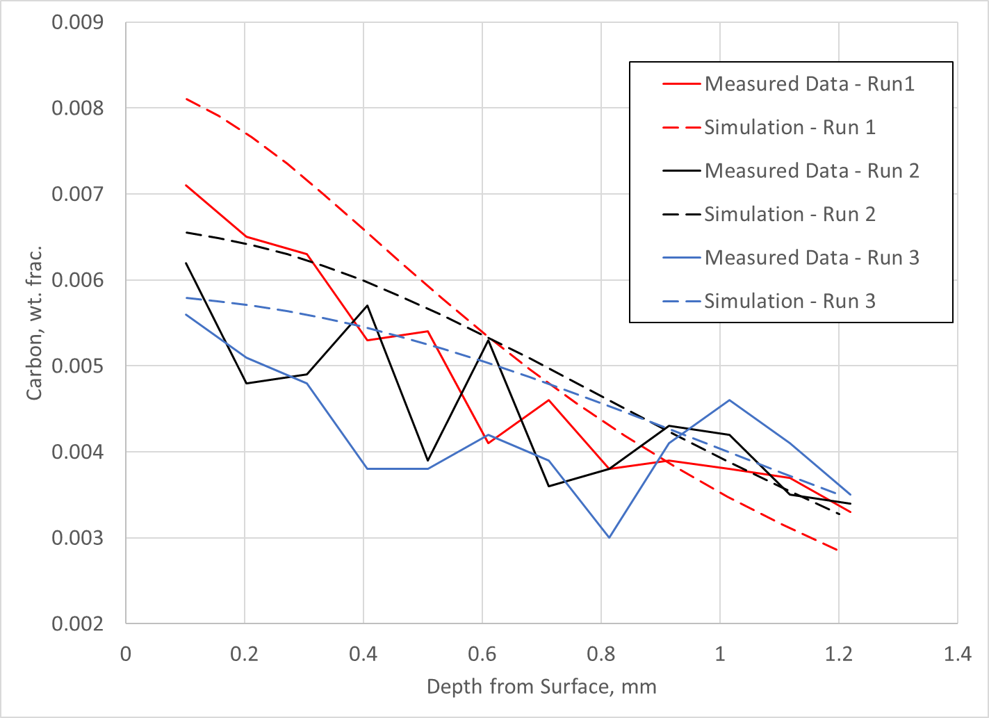
LPC experiments were conducted whereby 4-inch diameter cylinders made of Ferrium C64 were subjected to three different LPC cycles with the only difference in the cycles being the final diffuse time. Each run used a progressively longer final diffuse time. Carbon measurements were made using a LECO burn. Unfortunately, this method of carbon analysis gives no indication as to the amount of carbon in solid solution and the amount of carbon in primary carbide form.
Regardless, the data was fit to diffusivity and primary carbide formation/dissolution kinetics parameters used in the DANTE carburization model and compared to the experimental data. The results are shown in Figure 1. As can be seen, the match between prediction and experiment is reasonable, with a significant amount of scatter in the experimental data. With the ability to predict carbon diffusion and carbide formation/dissociation, the DANTE model can now be used to predict and design LPC schedules for Ferrium C64 steel.
Case study
The following is a case study for the redesign of an LPC schedule for a ring gear using the DANTE heat-treatment simulation software. The original LPC schedule, consisting of six boost-diffuse steps, was producing too many primary carbides during the process, and, as a consequence, rolling contact fatigue performance was very poor. Since the carbon potential should act uniformly around the circumference of the gear and each tooth should behave the same with respect to carbon diffusion, only a single tooth was modeled.
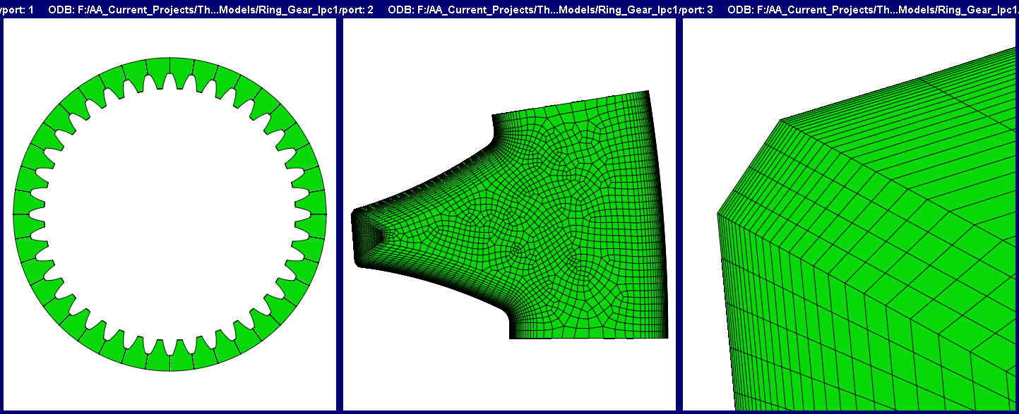
Figure 2 shows the full CAD model of the gear (left), the single tooth meshed model (center), and a closeup of the gear tip corner mesh (right). An extremely fine surface layer of elements is required to capture the steep chemical gradient that exists near the surface during an LPC process. Only the cross-section is shown, though the gear does have a height. The gear has a 5.5-inch outer diameter, a 4.5-inch inner diameter, a 0.60-inch height, and 40 teeth. The gear is made of Ferrium C64 with a base carbon of 0.1%. The model contains 233,850 hexagonal linear elements and 245,055 nodes.
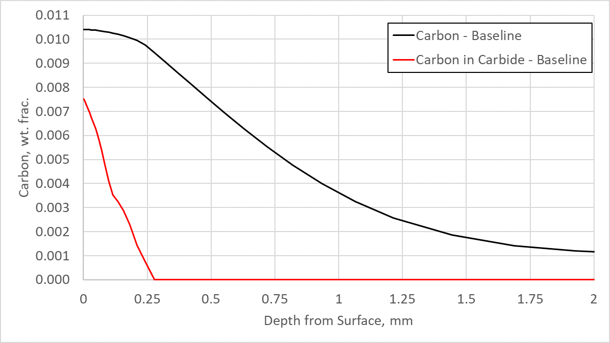
The case depth was originally designed for 0.75 mm on the flank of the tooth, with a carbon value of 0.3% resulting in a hardness value of 50 HRC for Ferrium C64 when tempered at 495°C. Figure 3 shows a plot of the carbon in the austenite matrix (carbon) and the carbon in primary carbide form (carbon in carbide) from the surface of the flank toward the core. As can be seen, a great deal of carbon is tied up in primary carbide form — approximately 0.75%. These primary carbides, if not dissolved either during a reheating process to form austenite or at the end of the carburization cycle, can be extremely detrimental to fatigue performance. Figure 3 also shows that the case is deeper than it needs to be, at 1.1mm.
An added benefit of using simulation software like DANTE to design LPC schedules is the ability to witness the effect of each individual boost-diffuse step. It is therefore possible to know when to reduce the boost time to avoid large primary carbide formation and how long to diffuse to ensure the primary carbides are dissolved to a sufficiently small size. Most medium- and high-alloy steels will form primary carbides during the boost step, regardless of the time. So, it is important to allow enough carbon to enter the part before beginning the diffuse step.
Controlling the length of the diffuse step then becomes critical in ensuring the primary carbides have properly dissolved before beginning the next boost step. Figure 4 shows the predicted carbon in the austenite matrix (carbon) and the carbon in primary carbide form (carbon in carbides) at the surface of the flank for the baseline model over the total time of the process. As can be seen, the carbon in primary carbide form continues to increase as the process progresses. The long final diffuse begins to allow for decomposition, but the time is not long enough.
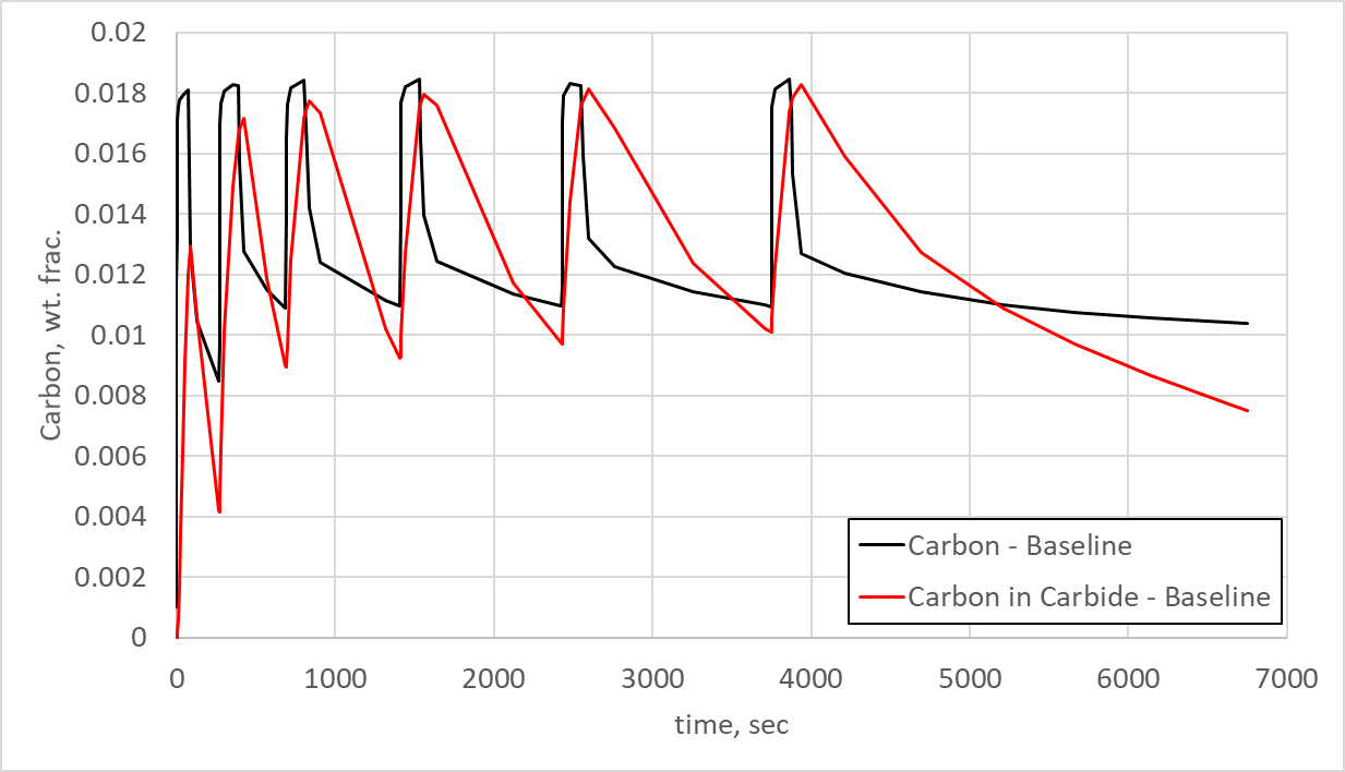
Figure 4 also indicates that the diffuse times are much too short, as the carbon in carbide does not dissociate back into the austenite matrix, but remains more than 1.0% for most of the process. The boost times seem reasonable, since the carbon in primary carbide form rises approximately 1.2%. This is reasonable for Ferrium C64, as the high level of chromium causes rapid formation of primary carbides. The important insight gained from Figure 4 is that the diffuse times are far too short to properly dissolve the primary carbides back into solid-state solution.
A new schedule
To ensure the primary carbides dissolve completely before hardening, a new schedule was developed with the aim of reducing the carbon in primary carbide form. To reach this goal, three boost-diffuse steps were removed, and the diffuse times increased substantially. This increase in diffuse time added approximately one-half hour to the schedule, which is acceptable given the positive results. Figure 5 shows the predicted carbon in the austenite matrix (carbon) and the carbon in primary carbide form (carbon in carbide) for the total process time at the same surface location on the flank as Figure 4 for the baseline LPC schedule.
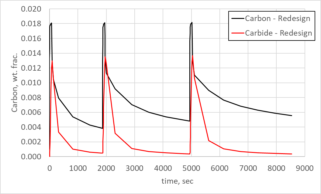
As can be seen in Figure 5, the primary carbides now have time to dissolve during each diffuse step and are nearly eliminated by the final diffuse step. It is also interesting to note that the carbon in primary carbide form rises to 1.3% during each boost step before dissolving to a minor fraction of a percent. Comparing to Figure 4, this matches the first two boost steps, but the baseline carbon in primary carbide form contained 1.8% carbon in later boost steps. So, the redesign had a significant effect on primary carbide formation.
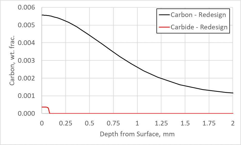
The baseline model also showed the surface carbon near 1.0%, which is much higher than what is needed to reach a hardness of 60 HRC. For Ferrium C64, a surface carbon of 0.55% is sufficient to reach a surface hardness of 60 HRC after tempering at 495°C. Therefore, the surface carbon was also reduced in the redesigned schedule. Figure 6 shows the carbon in the austenite matrix (carbon) and the carbon in primary carbide form (carbide) from the surface of the flank toward the core for the redesigned schedule. By reducing the surface carbon, this material was able to meet the required hardness, case depth, and avoid significant primary carbide formation during the LPC process. The carbon in primary carbide form on the surface can now be easily removed with a light finishing operation, whereas a significant amount of grinding would have been required to remove the primary carbide layer from the baseline process.
Conclusion
It has been shown that it is possible to model a low-pressure carburization process, including the formation and dissociation of primary carbides using the DANTE heat-treatment simulation software. The primary carbide kinetics can be determined through fitting experimental data to model parameters that include diffusivity of carbon in austenite and the formation and dissociation of primary carbides.
In this case, LPC experiments were conducted on Ferrium C64 cylinders, and parameters inside the DANTE carburization model were fit from the experimental data. The model was then used to redesign an LPC schedule for a gear component. It was shown, through modeling, that the original schedule was producing too many primary carbides and also had a surface carbon that was too high. A schedule was then successfully redesigned using DANTE in which the surface carbon was reduced to 0.55% and the primary carbides reduced to a small amount in a shallow surface layer. The same procedure of conducting LPC experiments and fitting the data to a model that includes carbon diffusivity through austenite and the formation/dissociation of primary carbides can be applied to any medium- or high-alloy steel.


 general practice for CQI-9 and AMS2750E")


