


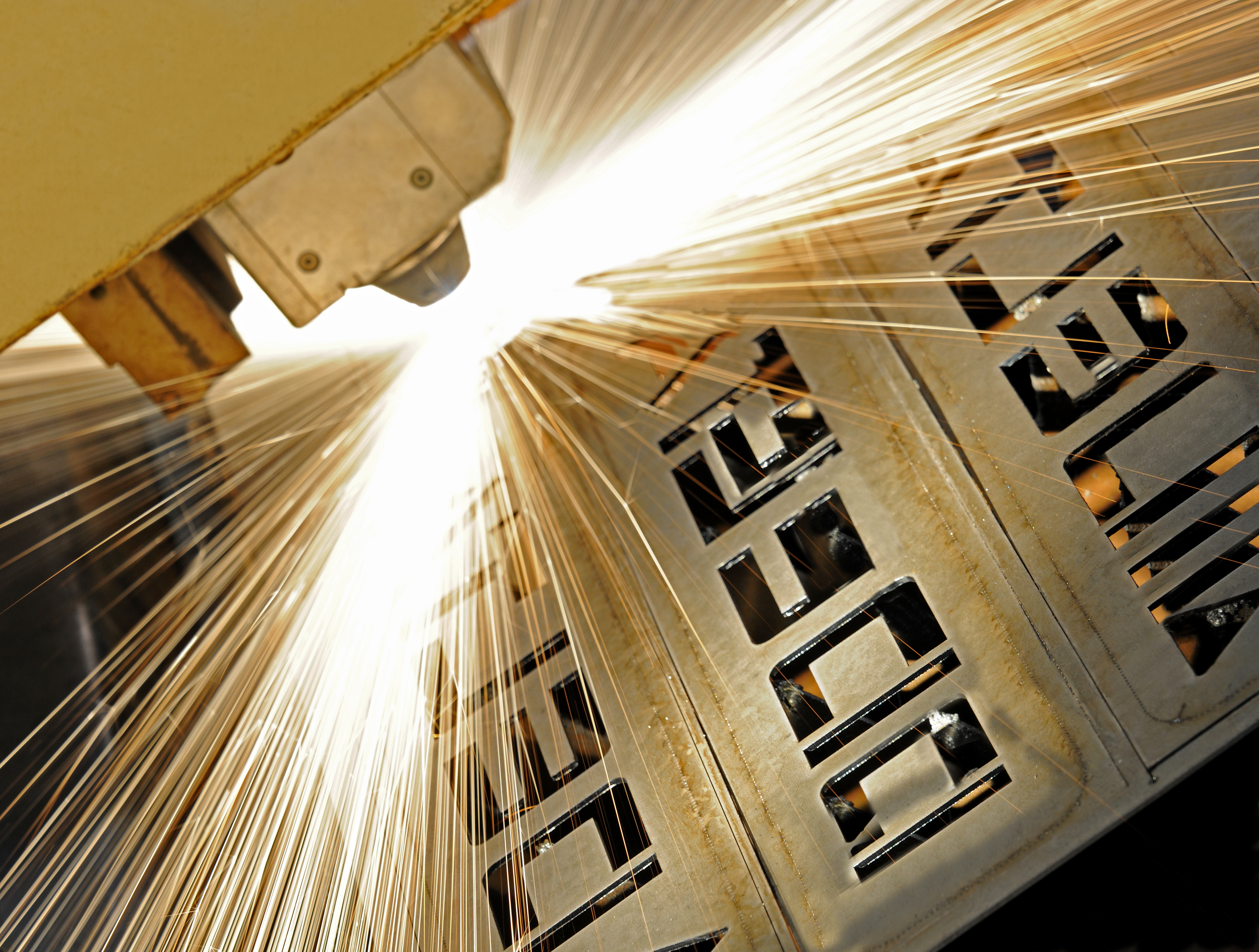
Laser cutting of metals and other materials has grown rapidly due to developments in laser power, advancements in CNC automation, and decreasing costs. The industrial gas requirements for lasers have been quite dynamic as well.
Depending on the material to be cut, the process or assist gas can be air, oxygen, or an inert gas (nitrogen or argon). Each gas provides different production results. Lasers operating with O2 combine the energy of the laser with the exothermic energy from the reaction of O2 with the metal to make the cut. The cut surface with O2 is not as clean as one made with an inert gas. When an inert gas is used as the assist gas, the laser provides all the energy to melt the metal. The role of N2 or argon is to clear away the molten material from the area of the cut. These gases also inert the cut area and facilitate cooling of the surface until it is at a low enough temperature to avoid oxidation. The result is a clean, oxide-free surface.
OEM Scope
There are many manufacturers of lasers and laser cutting systems. The optimum system requirements depend on many factors including: dimensional accuracy, surface finish, cut-edge quality, type of material, thickness, post-processing needs, overall cutting time, and the amount of material to be cut. Based on all of these inputs, the OEM will design a laser cutting system that will typically have an industrial gas requirement (O2, N2, or argon). The OEM will also define the required purity, flow rate, and pressure of the gases consumed in the laser. The focus of this article is to provide information on the supply systems and gases that support laser cutting.
Purity
Many laser OEMs refer to overall purity of the gases used and typically require grade 5, or five 9’s, purity. The purity table shows the purity of various grades.

Often times it is more meaningful to evaluate the impurity levels rather than overall purity. The main impurities of concern are those that can oxidize the material being cut, such as the PPM O2 level and the dew point (moisture) level. Most industrial liquid N2 grades meet the five 9’s purity level. The dew point of gaseous N2 from a liquid N2 supply is typically less than minus 90°F (< about 3 PPMV).
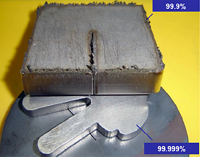
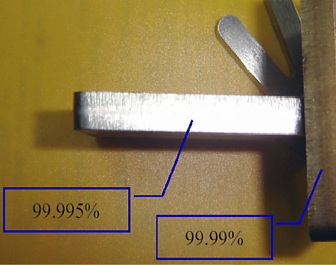
The impact of N2 purity on cleanliness of the laser cut is shown on various metal pieces in Figures 1 and 2. A bright, clean surface is achieved only with a purity of 99.995 percent or greater.
Piping
The houseline piping needs to be properly selected to handle the maximum pressure and peak flow rate. Since the required flow rate to the laser varies with the thicknesses and type of material being cut, it is extremely important to understand the range of thickness to be cut. With high flows and high initial supply pressures, line size is extremely important due to the concern for potential pressure drops, especially when growth is not factored into the initial piping design.
For lasers using O2, there is an additional requirement for piping and flow components; they need to be “oxygen cleaned and oxygen compatible.” Equipment used in oxygen service must be cleaned according to strict industry guidelines. The most commonly used specifications in the industry are CGA G-4.1, NFPA 99, and ASTM G93. “Oxygen cleaning” or “cleaned for oxygen service” means that all particulates and organic residue have been removed from the surface of the piping and the components. Oxygen combines readily with many elements to form compounds called “oxides.” One example is iron oxide, or rust, that forms on iron in the presence of oxygen and moisture.
Flow Capacity
The houseline piping needs to be designed to provide the required flow rate at the required pressure.
If the piping system does not have the required flow capacity, excessive pressure drops will occur. A supply system will have a certain initial maximum pressure and flow rate capacity. Once gas starts flowing down the houseline, its pressure can only decrease. The goal of a properly designed houseline is to minimize the pressure drop along the houseline and provide the required flow of gas at the minimum required pressure.
The laser OEM specifies a certain minimum gas pressure at the inlet to the laser under peak flow conditions. When there are multiple lasers on a common houseline, the laser at the furthest point from the supply system is the most easily starved for pressure and flow. Pressure drops can be caused by inadequate pipe diameter, excessive pipe length, circuitous piping (e.g. elbows, T’s, pipe diameter reduction, etc.), and/or components with low-flow capacity (isolation valves). The correct flow component selection is an important part of a properly designed houseline network.
Table 1 illustrates the impact of pipe sizing on pressure drop for three different sized pipes at flow rates from 1,000 SCFH to 6,000 SCFH. In this evaluation, the gas is N2 with an initial pressure of 450 PSIG and a pipe length of 250’. The pressure drop is the difference between the inlet pressure and the pressure as the gas exits the pipe. A 0.5” diameter pipe with a flow rate of 6,000 SCFH N2 has a pressure drop of 40.44 PSI. This means that the pressure at the end of the 250’ pipe run will be (450 – 40.44) = 409.56 PSIG.
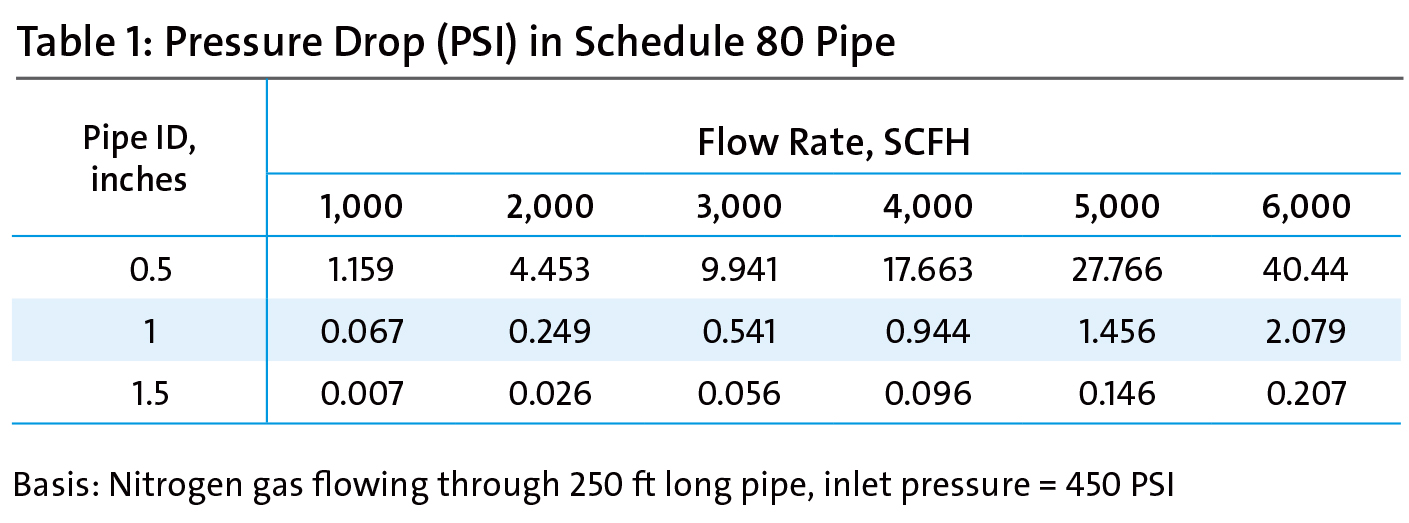
If, instead, the houseline was 1.5”, the pressure drop would only be 0.207 PSI with a resultant downstream pressure of (450 – 0.207) = 449.8 PSIG.
Although oxygen itself is nonflammable, combustible materials burn more strongly in oxygen. The higher the oxygen percentage and the higher the pressure, the stronger the combustion and the lower the required ignition temperature.
Materials that do not normally ignite in atmospheric air will burn and may explode in an oxygen-rich environment.
Pressure Rating
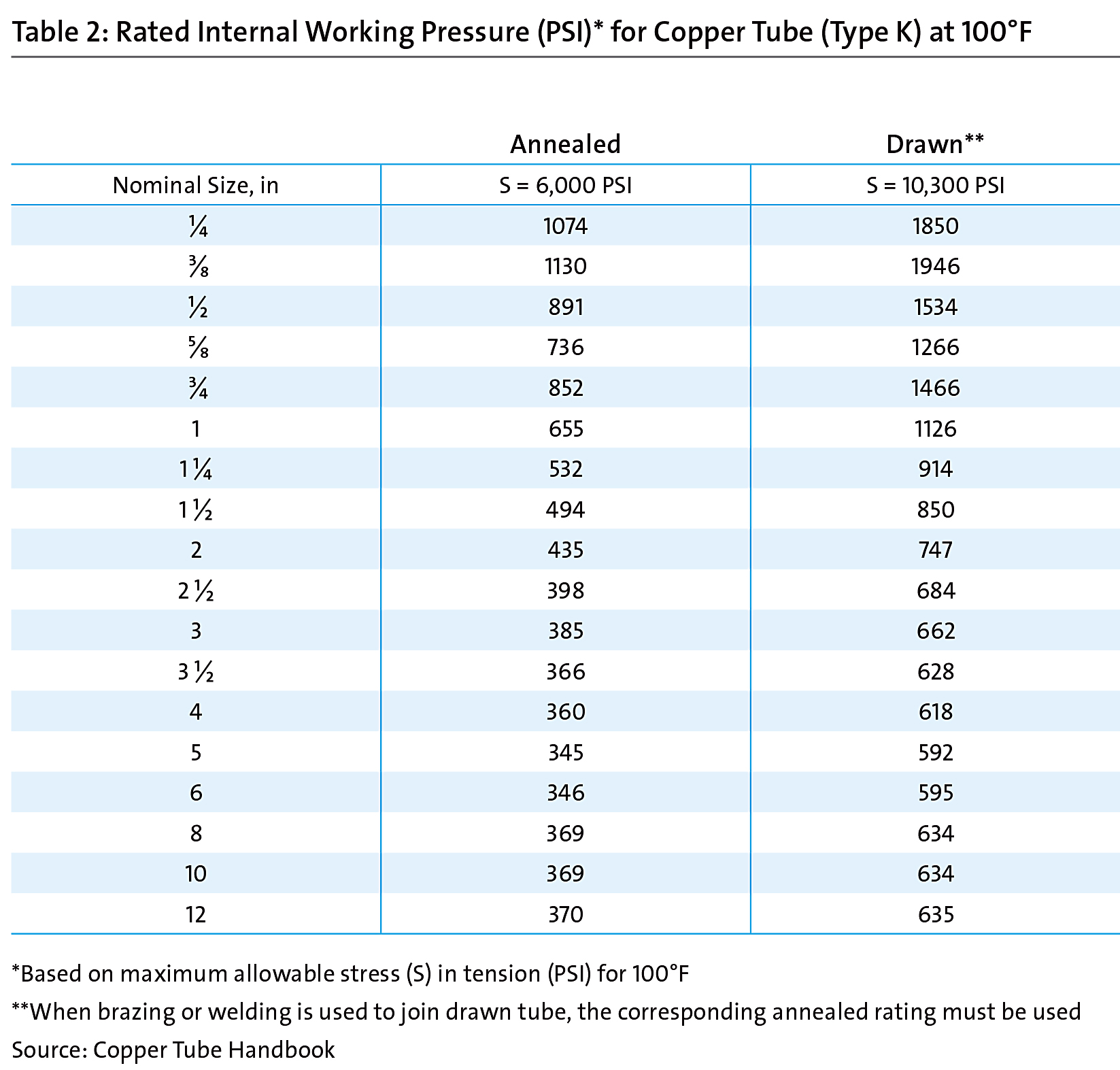
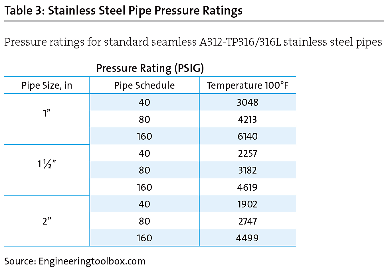
The houseline piping must be designed to handle the expected pressure. Tables 2 and 3 show the rated working pressures for Type K copper tubing and welded stainless steel pipe, respectively. There is tremendous variation in pressure rating depending on the diameter and material, especially for the larger-diameter copper tubing. If a new houseline is being installed, it usually makes sense to oversize the pipe with regard to both flow capacity and pressure rating to account for future production growth.
Product Mix
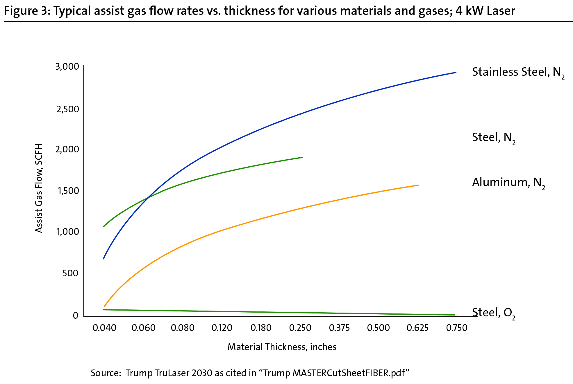
The amount of N2 for assist gas for cutting stainless steel can vary from several hundred SCFH for relatively thin material (< 0.1”) to several thousand SCFH for > 0.5”. Therefore, it is important to understand how much cutting time will be associated with each grade and thickness. After this has been determined, the monthly gas consumption can be calculated by multiplying the flow rate for each material and thickness times the amount of monthly cutting hours. This monthly consumption can be used to optimally size the industrial gas supply system.
Figure 3 illustrates typical gas flow rates for various materials and thicknesses, using a 4 kW laser. This data stresses the importance of understanding the product mix when sizing a system since the assist gas flow rate can vary significantly based on material thickness.
Industrial Gas Supply Modes
There are many different gas supply modes available. The one that fits a specific requirement is determined by the supply system’s capability for maximum pressure, flow rate, and storage capacity. Over the years, the flow rate and pressure requirements for the assist gas in laser cutting have increased.
This has made the selection of the proper N2 supply system even more critical because not all N2 supply systems have the same pressure and flow capabilities. All aspects of an industrial gas supply system must be designed properly so that safety, efficiency, and performance of the laser can be assured. The following is a summary of the main supply options:
Cylinders: These are the smallest, simplest mode of supply. The gas is at high pressure, but the amount of stored gas is minimal. A typical cylinder contains about 275 SCF at 2,200 PSIG. Cylinders can be manifolded together to supply more volume.
Microbulk: This supply mode provides gaseous N2, O2, or argon from a relatively small cryogenic liquid tank. These tanks range in size from 230 liters (5,658 SCF) to 5,000 liters (123,000 SCF). These supply systems have a wide range of pressure capabilities. Some are as high as 500 PSIG MAWP and are able to supply a houseline with a pressure of 450 PSIG. These supply systems can have a limited flow capacity; therefore, the peak process flow requirement must be compared with the systems flow capacity. In some cases, it makes sense to use two or more microbulk tanks for increased capacity. The use of more than one tank can facilitate a continuous supply of process gas during the filling of the tanks. One tank is online while the other is being filled.
Bulk Tanks: These are the traditional industrial gas tanks. They range in size from 1,500 gallons (140,000 SCF N2) to greater than 11,000 gallons (1,024,210 SCF N2). Most of these tanks have a 250 PSIG MAWP, so the maximum houseline pressure is about 200 PSIG. Since this pressure is too low for most lasers, additional equipment must be added to enable a higher supply pressure. There are commercially available gas supply systems that take liquid from the supply tank and then pressurize it for the process. Such systems have high flow and pressure capability. Houseline pressures as high as 550 PSIG are available for N2.
Another alternative is to use the bulk tank to supply a cryogenic pump, a high-pressure vaporizer, and gaseous hydril tubes to provide a high-pressure supply system.
High-Pressure Bulk Tanks: There are also other supply systems that can produce high pressure and high flow rates. These include high-pressure bulk tanks. They can operate as high as 600 PSIG MAWP. Sometimes these tanks have a cryogenic ground pump so they can be filled from the supply trailer without depressurizing (venting) the tank and interrupting the supply to the use point. The ground pump enables the delivery tanker truck to overcome the tank’s operating pressure, thus allowing an uninterrupted supply of high gas pressure to the laser.
The best choice of a supply system depends on the amount of usage (SCF/month), the peak combined flow rate (SCFH), the production schedule (hours/month of cutting), and the minimum houseline pressure. The anticipated growth of the gas requirement should also be considered in this evaluation.
It is important to take into account how the tanks are filled and whether the tank needs to be depressurized in order to fill the tank. This can result in a loss of gas supply during the fill procedure. The venting of gas during tank depressurization also has an economic cost since the vented gas is lost. Venting also occurs during the switching between liquid containers during normal operation of the gas supply system.
The last factor in determining the best mode of supply is whether there needs to be a continuous supply.
Some supply modes require the tank to be depressurized while being filled.
Pressure Regulation
If a pressure regulator is needed on the houseline, it is important to select one that has adequate flow capacity. An improperly sized pressure regulator can potentially limit the downstream flow. Many standard cylinder pressure regulators can handle the pressure but can only provide a limited flow capacity and should not be used. An improperly chosen pressure regulator can become a flow restriction.
Summary
There are many factors that must be considered when designing the industrial gas supply system. The supply system must be engineered along with the houseline piping and associated components to ensure that it operates safely, properly, and efficiently to meet the demanding laser requirements.


 general practice for CQI-9 and AMS2750E")


