


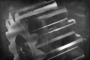
Pit Low Pressure Carburizing (LPC) for case hardening of large gears is a new approach to a traditional technology. Today’s manufacturing environment demands process, quality, and environmental improvements. Heat-treatment applications can have an extremely large impact in the reduction of overall costs and time. LPC of gears have been traditionally conducted in horizontal batch configurations with disadvantages that include the limitation of maximum gear size produced deterring the idea of LPC for large gears. Vertical designs allow for the maximum use of a furnace working volume; however, it comes with its own challenges. Vertical LPC oil quench designs are demanding as they must be connected vertically (requiring a tall shop height and pit for quenching). Vertical vacuum furnaces with high pressure gas quenching (HPGQ) can be used; however, quenching in gas has its limitations vs. oil quenching. Traditional atmosphere pit carburizing designs offer unwanted (yet accepted) effects, including a flammable atmosphere, cumbersome atmospheric generators, intergranular oxidation, etc. The pit LPC approach allows LPC to take place safely and environmentally friendly in a vacuum-heating chamber. Upon the conclusion of the boost/diffusion cycles, the component(s) can be removed from the heating chamber and placed into a separate oil quench vestibule. Typical LPC furnaces do not allow this as degradation of internal materials take place when exposed to oxygen. The pit LPC design has a heating system that can operate under vacuum and can be exposed to oxygen during material transfer to quench. Deep case depths require long carburizing cycle times, especially at lower temperatures, whereas the benefits of pit LPC design allows carburizing at higher temperatures such as 1,800-1,900°F (980-1,040°C) reducing the carburizing times drastically (up to 50 percent) compared to lower temperatures, saving operating costs and case hardening times.
Introduction
Modern case hardening by carburizing, a practiced method to surface harden steel, is reaching its centennial anniversary. Although case hardening within carbon environments (pack carburizing) was practiced prior to the 20th century, modern case hardening received its notable start in the 1920s. Now, 100 years later, there are several different methods to introduce carbon to austenitized ferrous metal surfaces, increasing the carbon concentration at the surface by the diffusion of carbon toward the core, creating the case-hardened carbon profile. Austenitized steel is a phase transformation of steel at elevated temperatures above 1,340°F [725°C] and allows higher levels of carbon to be absorbed into the steel surface. These carburizing methods include:
- Pack carburizing.
- Liquid (salt bath) carburizing.
- Gas carburizing.
- Low pressure carburizing (LPC).
The ending result of these methods provides a hard and wear resistant surface with a soft and/or tough core for low carbon steels and does not have a high degree of hardenability. These processes are conducted in heat-treatment furnaces of varying designs, shapes, and sizes.
Modern carburizing heat-treatment furnaces can be produced in continuous, semi-continuous, and batch type, and they can be provided in horizontal, vertical, and rotary configurations. Manufacturing volumes, component geometry, material grade, variety of geometries, and material grades all influence the optimum furnace type and configuration. Material grade and cross sections can drastically influence the design based on how intense the quenching media is needed to obtain the desired hardness. Since carburizing is typically conducted on low carbon and, due to its low hardenability, the cooling process must be rapid to prevent the austenite transformation back to ferrite/pearlite in the core. Higher carbon steels typically do not require as aggressive of a cooling process, and slower quenching media can be used.
Carburizing case depths vary drastically depending on the size and demand a component is going to be subjected to. The required carburizing case depth directly affects the duration of the carbon boosting. The deeper the case depth, the longer the carbon boost and diffusion stage will be while at the austenitizing temperature. When deep case depths are required, extremely long furnace process times are required when carburizing in the 1,700°F (925°C) range. For example, 0.08” (20 mm) requires approximately 12 hours whereas 0.15” (3.8 mm) requires approximately 36 hours. When carburizing at lower temperatures, the diffusion of carbon takes place much slower and can take up to twice as long.
In general, when small working volumes and low weights are required, small horizontal furnace configurations are typically used. Contrast this to large heavy loads, and the large vertical furnace configuration becomes the preferred method of heat treatment. Since these large components tend to be quite heavy, overhead crane material handling typically is the preferred method of material transfer, and the furnace hearth can be optimized to accommodate the large masses. It is also worth noting that comparing the working volume of a horizontal furnace to a pit furnace, the pit furnace will be less costly to manufacture, in addition to having the ability to handle greater mass per working volume. Pit-furnace hearths can be constructed to handle much greater load masses since they are loaded via an overhead crane system vs. bottom supported loads as in horizontal furnaces.
When manufacturing requires carburizing on large diameter components or components that are long and narrow, the chosen furnace configuration often will be a pit type. Long components typically require hanging during heat treatment as horizontally supporting them often leads to sagging and deformation. Long components either can be large and bulky (with small volume loads) or small in diameter (with large volume loads). It is common for large components that require carburizing to have deep case depths; this means that components will be in the furnace for long durations keeping the furnace occupied and not able to process additional loads. Considering that deep case depths on large components tie up the furnace for long durations, manufacturers are driven to heat treat as many components in a furnace as possible, affecting the need for the furnace to handle loads with heavy masses and large geometric footprints.
Carburizing Methods
Pack Carburizing
Pack carburizing is one of the earliest forms of carburizing, and it provides the addition of carbon to a steel component via a decomposition of a solid compound in a sealed metal container as illustrated in Figure 1.

Pack carburizing processes higher temperatures than that of gas and liquid carburizing and does not have the ability to directly quench the carburized components, which are enclosed in the steel container with solid carbonaceous compounds. This process is very challenging to control, produces non-repeatable results, requires an additional core refinement process (due to large grains and slow cooling), and a case refinement process. Therefore, pack carburizing is not commonly practiced due to its labor intensiveness, lack of process control and environmental issues, giving way to liquid and gas carburizing methods.
Liquid (salt bath) Carburizing
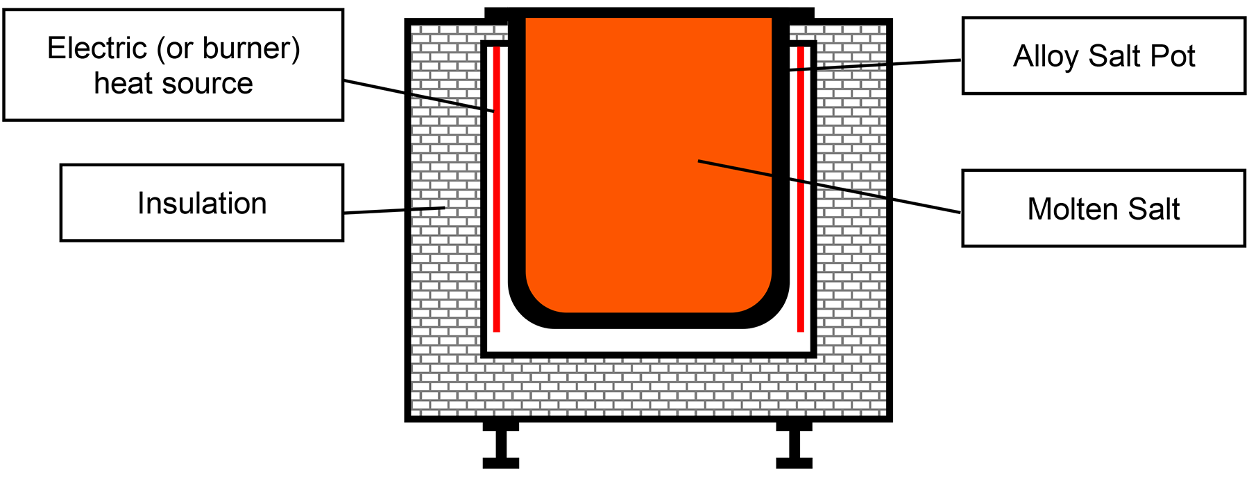
In liquid carburizing, steel components are submerged in a molten-salt bath and held at temperatures above a material’s austenitic transformation range. The salt bath, sometimes referred to as a chloride bath, consists of sodium cyanide (the carbon source), barium chloride, and sodium chloride. The decomposition of these salts at high temperatures causes the carbon to decompose near the austenized steel surface and diffuse into the steel. Also note that nitrogen can sometimes diffuse into the surface in addition to the carbon. Salt bath heating operates in the 1,560-1,650°F (850-900°C) range for shallow cases and 1,650-1,750°F (900-950°C) range for deeper cases. Salt baths provide excellent temperature control, rapid heat transfer, and allows for direct quenching after carburizing. Figure 2 illustrates a typical construction of an electrically heated salt bath furnace using a high-temperature alloy salt pot to contain the molten salt.
Salt-bath carburizing, like pack carburizing, is not a commonly practiced carburizing method in modern industry, and with salt-bath processing, it derives several disadvantages. When at higher temperatures, the degradation of the salt bath and furnace components happens at accelerated rates, requiring the replenishment of salt and constant furnace maintenance. Due to the decomposition of the salt, a “sludge” forms and requires constant removal and recharging of the salt composition. Part washing is required after quenching, and, due to residual salt adhering to the component when hot and in the salt bath, liquid carburizing is not recommended for components that have geometric features such as threads, slots, and/or small holes. Additionally, the residual salt remaining on a component will contaminate the quenching media.
Gas Carburizing
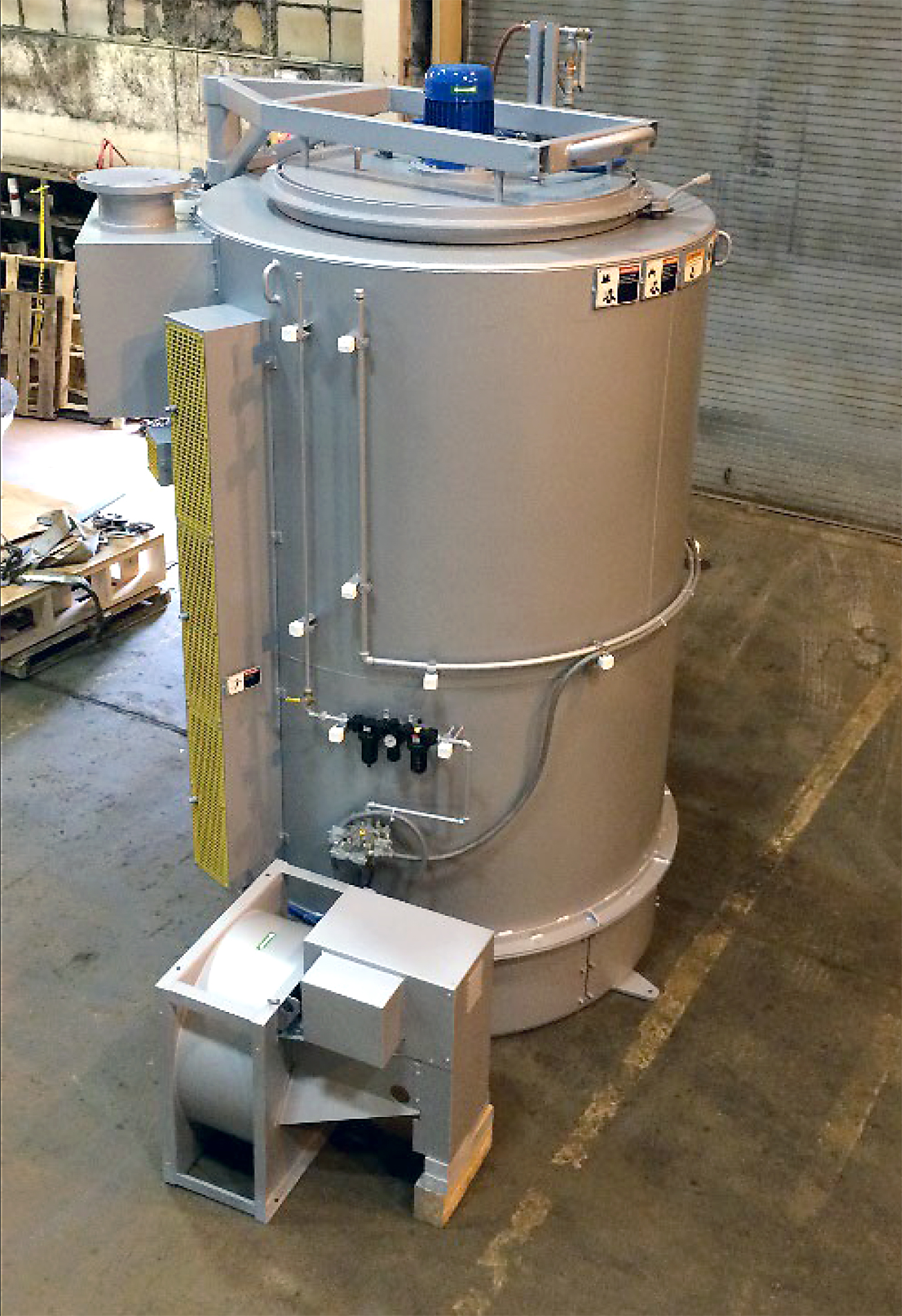
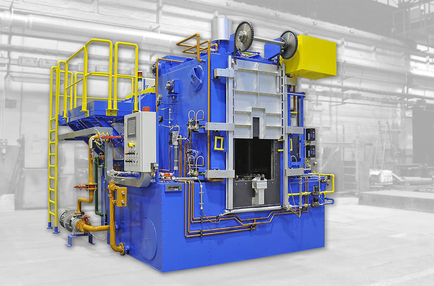
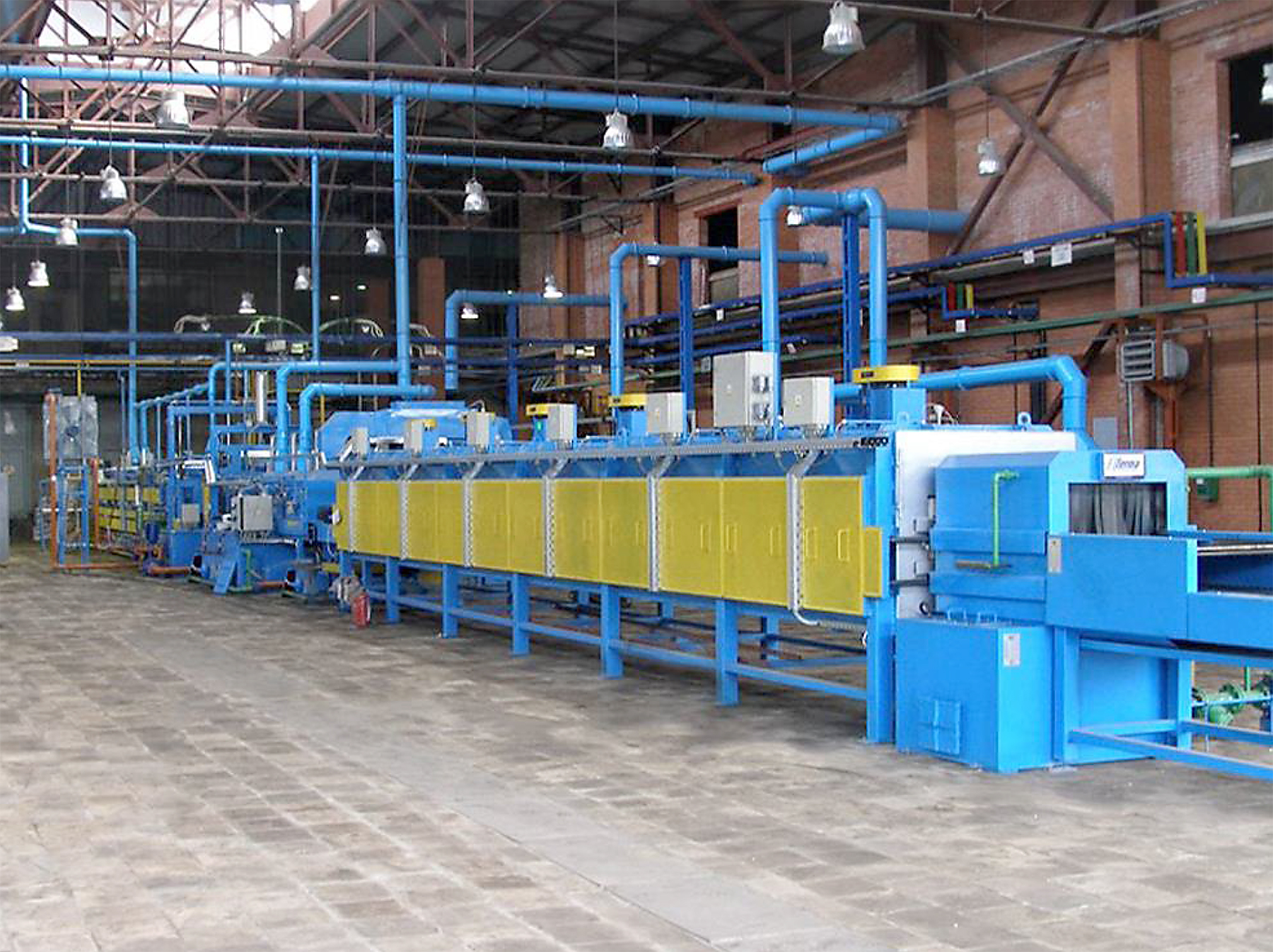
Gas carburizing, developed in the 1950s, became a favored technique due to the unreliable methods of pack carburizing and the associated issues with liquid carburizing. Currently, gas carburizing is the most widely used type of carburizing in modern industry. A wide variety of conventional furnaces including pit, box, continuous, and rotary types are used for gas carburizing and as in any heat-treating process, the proper choice of furnace design depends largely on component geometry, total production demand, and production flow. Figure 3 through Figure 6 provide types of atmosphere furnaces equipped for carburizing.
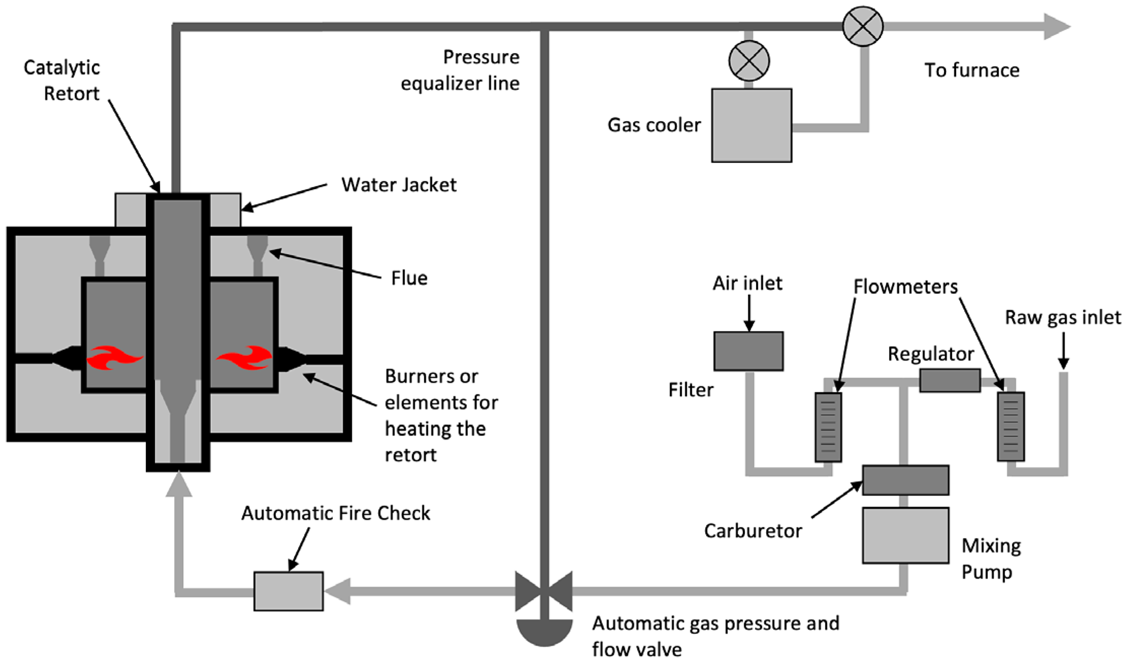
In gas carburizing, the carbon source, typically natural gas (or propane), composed largely of methane, is introduced to the furnace via an inert carrier gas such as nitrogen. The carbon and nitrogen sources are monitored and mixed external to the furnace in endothermic generator systems where the gasses pass through a heated retort containing a nickel catalyst, see Figure 7 and Figure 8. When the mixed gas leaves the retort, it is quickly cooled to prevent the reformation of carbon into soot and is sent to the furnace so the carbon can then diffuse into the steel. [3]
In comparison to pack or liquid carburizing, gas carburizing and its carbon potential allows deeper and higher carbon content cases to be obtained more rapidly.
“Carbon potential of a furnace atmosphere at a specified temperature is defined as the carbon content of pure iron that is in thermodynamic equilibrium with the atmosphere. The carbon potential for the furnace atmosphere must be greater than the carbon potential for the surface of the workpieces in order for the carburizing to occur. It is the difference in the carbon potential that provides the driving force for the carbon transfer to the parts.” [1]
This advantage is due to the carbon potential of the gas environment in the furnace being higher than that of the steel, and when the temperature of the steel is at 1,700°F (925°C), the surface of the steel is highly active and allows the surplus carbon in the atmosphere to diffuse into the surface. Increasing the temperature drastically affects the diffusion rate of carbon into austenite, for example 1,700°F (925°C) is approximately 40 percent faster than 1,600°F (870°C).
Disadvantages of Gas Carburizing
Carburizing at 1,700°F (925°C) happens to be the most common carburizing temperature. Due to atmospheric furnace construction characteristics, higher temperatures will generate excessive deterioration, especially in the thermally resistant alloy materials. Due to the furnace’s limitation to exceed 1,700°F (925°C), there is no significant way to speed up the diffusion rate of carbon into austenite.
In its early years, gas carburizing proved to be a process that was difficult to control as it relied on operators removing “shim stock” from within the furnace, weighing them as the process continued to assess how much carbon had been absorbed, which translated to the active case depth of the charge within the furnace at the time of its removal. At the time of gas carburizing, beginning operators were required to measure these shims at various stages of the process to ensure the desired carbon absorption was achieved. There were challenges associated with the measurement of “shim stock” as it was a continuous and labor-intensive monitoring process that ultimately led to inconsistent results from batch to batch. These inconsistencies and industries’ demand for more precise and reliable results led to the introduction of the oxygen probe atmosphere monitoring process. The oxygen probe gave the furnace the ability to measure the residual oxygen within a furnace’s atmosphere, which subsequently identifies the carbon potential of the atmosphere. [5]
However, control of the carbon potential for a given carburizing process is complex. Multiple systems are required (Figure 8) to create the proper atmosphere and dew-point control. Water vapor in the furnace atmosphere directly affects carbon potential, and control of dew point is critical to the success of carburizing. The catalyst within the endothermic generator will deplete over time, requiring monitoring and replacement when the reaction is insufficient. Excessive sooting within the catalyst will affect its performance and will require a burnout.
When a furnace has been idle for an extended period or has recently completed a soot removal burnout, the amount of new enriching gas needed to maintain a given carbon potential of an empty furnace is found to be much higher than would be expected. As time passes (typically 12-24 hours), the amount of enriching gas required to maintain the carbon potential decreases to a steady state value. This is a process called “furnace conditioning” and is the time that carbon is attracted to low temperature locations such as crevices and brickwork. However, as the furnace continues to operate, there are some locations in the furnace system where soot will continue to deposit such as sight ports and gas sample lines, which, over time, will affect the furnace’s carburizing capability. [1]
Gas-carburizing atmospheres are highly toxic and highly flammable and form explosive gas mixtures when mixed with air. A safety program emphasizing furnace operator training and preventative maintenance should be established and adhered to for all heat-treating operations using controlled atmospheres. Atmosphere gas discharged from the furnace to the operating environment must be burned to ensure poisonous carbon monoxide is converted to carbon dioxide. Pilot flames must always be maintained on atmosphere vent lines, and there must be a flame curtain that ignites automatically whenever a furnace door opens. [1]
Intergranular oxidation (IGO) takes place when steel is exposed to oxygen atoms at elevated temperatures. Oxygen is present from the process gas decomposition, and it then diffuses slowly into the steel-grain boundaries. This oxygen diffusion combines chemically with the existing elements that favor reactions with the oxygen. IGO is observed as microscopic cracks in a material’s surface up to approximately 0.006” deep but can be larger due to carburization time, temperature, and gas composition. In atmosphere furnaces, formation of IGO is not preventable, and its removal must be done via grinding, hard machining, polishing, or other mechanically suitable process. The only other way to eliminate IGO is to provide the heat-treatment process within an oxygen-free environment via low pressure carburizing (LPC). In this case, a vacuum furnace removes the oxygen present within its chamber via a vacuum pumping system prior to the start of heating.
Despite gas carburizing’s ability to monitor the temperature and gas composition, it still suffers from numerous limitations including the furnace equipment itself, hazardous operations, inconsistent case depths, and IGO. Industry, as a result, searched for an improved method of carburizing, leading to the invention of LPC.
Low Pressure Carburizing in Vacuum Furnaces
LPC differs from atmosphere gas carburizing. As its name suggests, it takes place at pressures below atmospheric pressures (low pressure) requiring the process to be carried out in a vacuum furnace instead of atmospheric furnaces. LPC found its origins in the 1970s where early users introduced propane as the carbon source to the process. Propane generated heavy sooting within the furnace, which led to arcing among the internal heating system if not properly maintained. This drove industry to further improve upon the process. In the 1990s, the introduction of acetylene as the carbon gas proved to have the desired chemical reaction of hydrocarbon gasses at low pressures without the unwanted effects of sooting. This was due to the steel’s ability to catalyze and decompose acetylene’s carbon molecules diffusing them into its surface. [5]
LPC process consists of loading a charge in the vacuum furnace; the door is then closed, and the vacuum pumping system begins removing oxygen from the chamber. Once the proper vacuum level is reached, the heating system is turned on and heats the charge to the desired austenization temperature, typically between 1,660-1,750°F and then LPC can begin. The LPC process consists of a series of acetylene boosting and diffusion segments where the acetylene is precisely introduced to the heating chamber via mass flow controller(s) at approximate pressures of 8 torr [10 mbar] then followed by a diffusion segment where the boosted carbon, which has saturated the steel surface, diffuses toward the materials core. This cycle is repeated with varying times and segments as needed to achieve the desired effective case depth (ECD). The alternating segment pattern is needed as the catalytic decomposition (or cracking) of the acetylene takes place much faster than the diffusion of the carbon into the steel [5]. Once the ECD is achieved, and depending on alloying elements, the charge can either be directly quenched in HPGQ or in oil or the furnace can be lowered in temperature to 1,500-1,550°F for material stabilization prior to quenching.
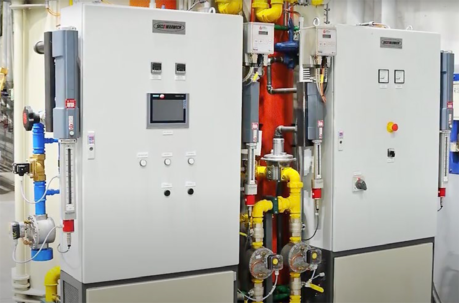
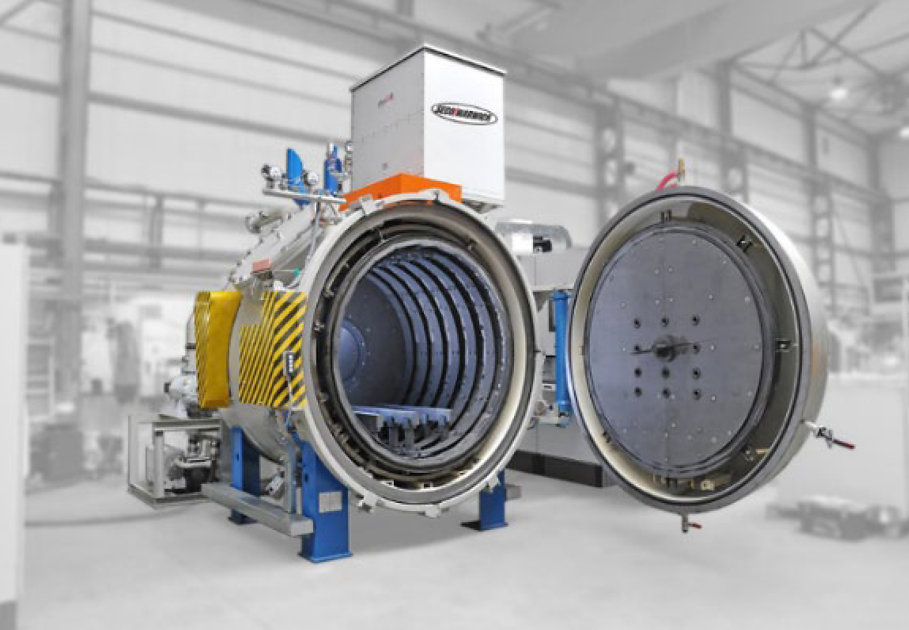
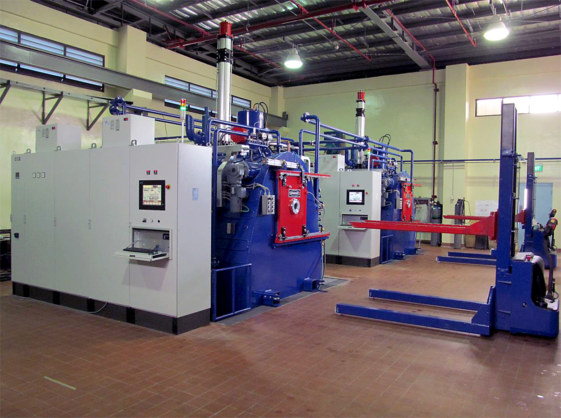
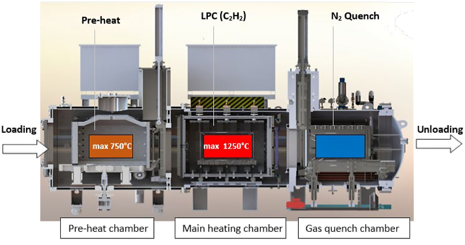
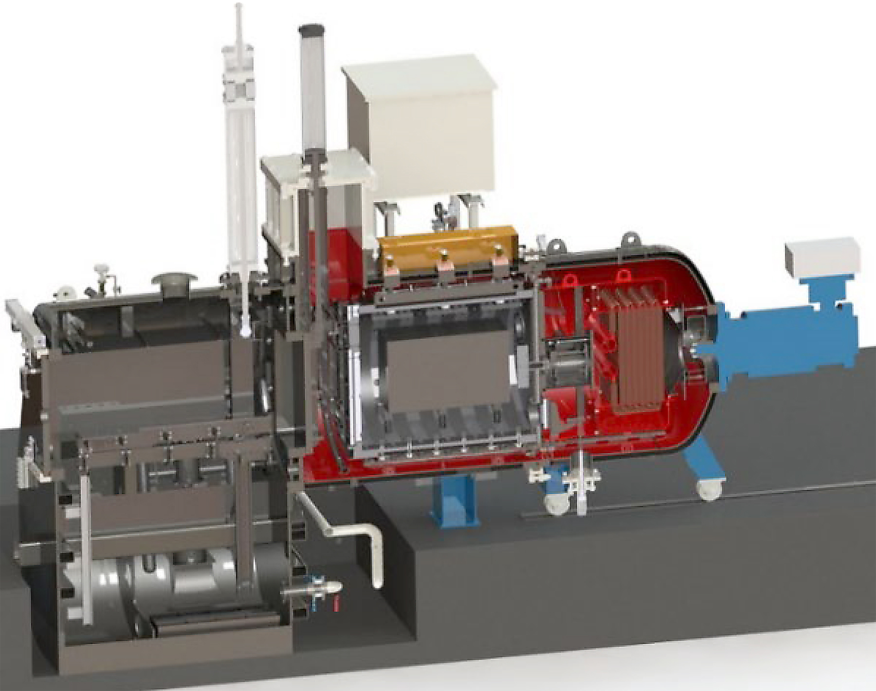
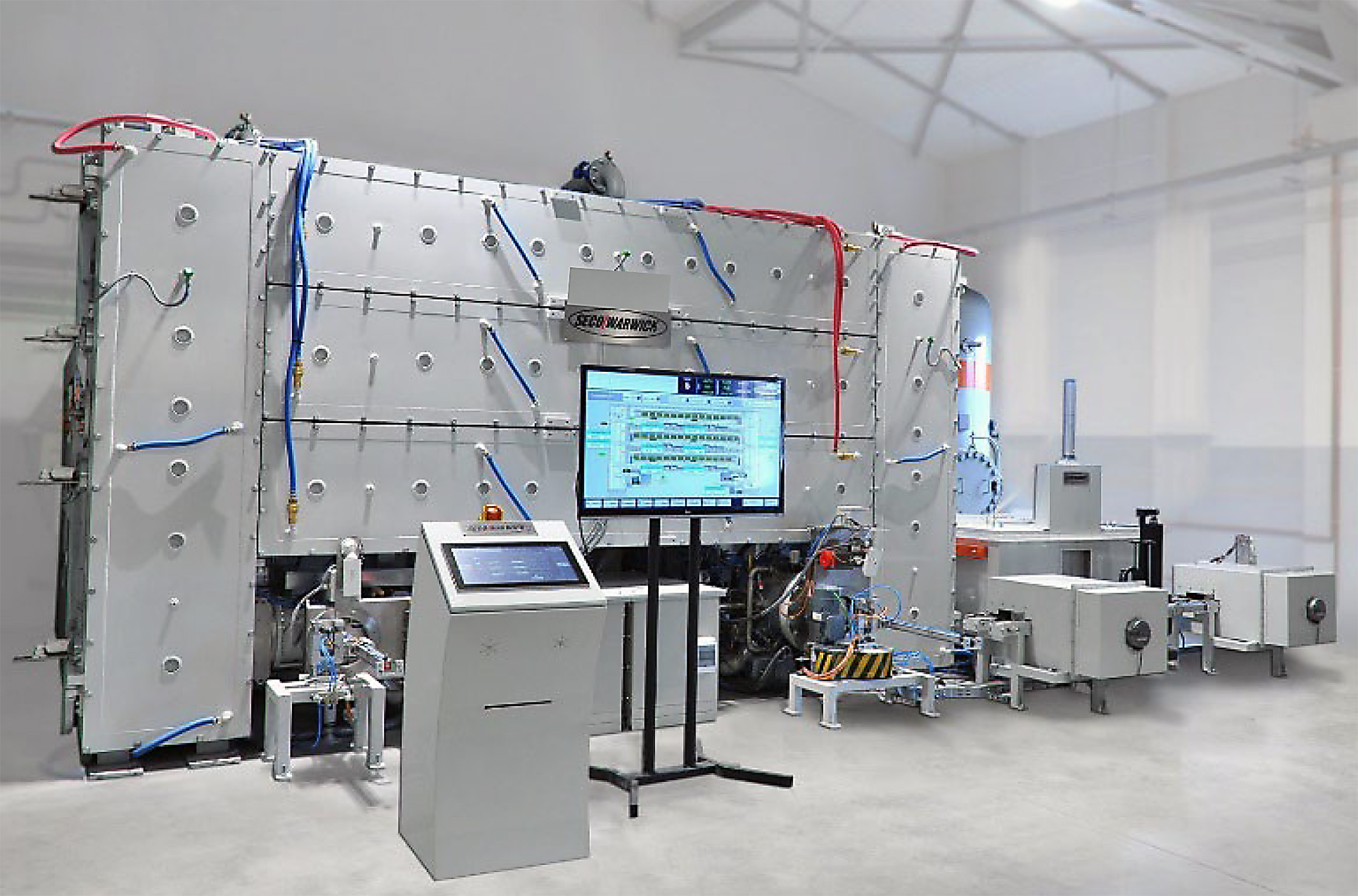
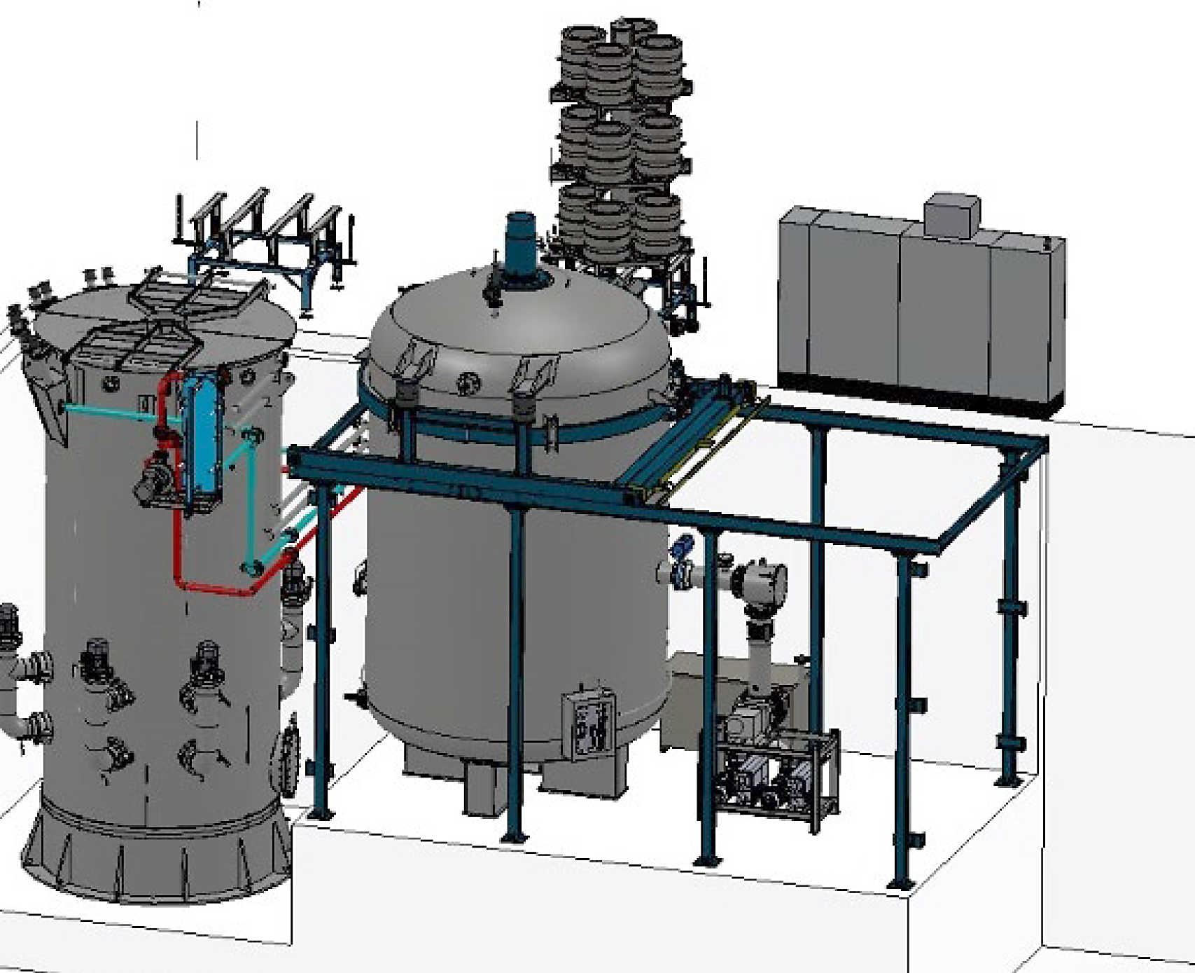
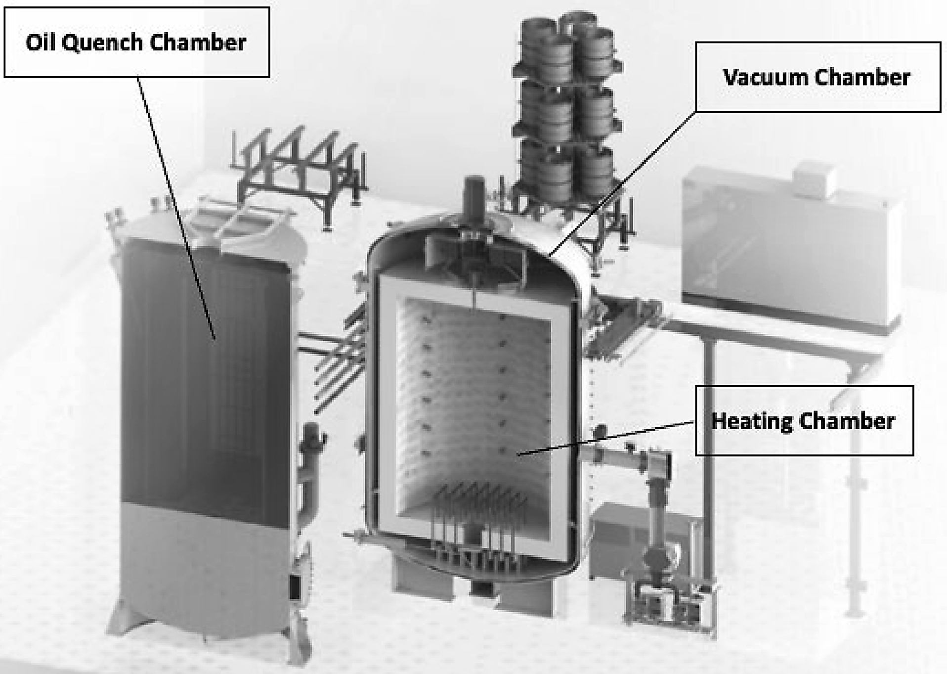
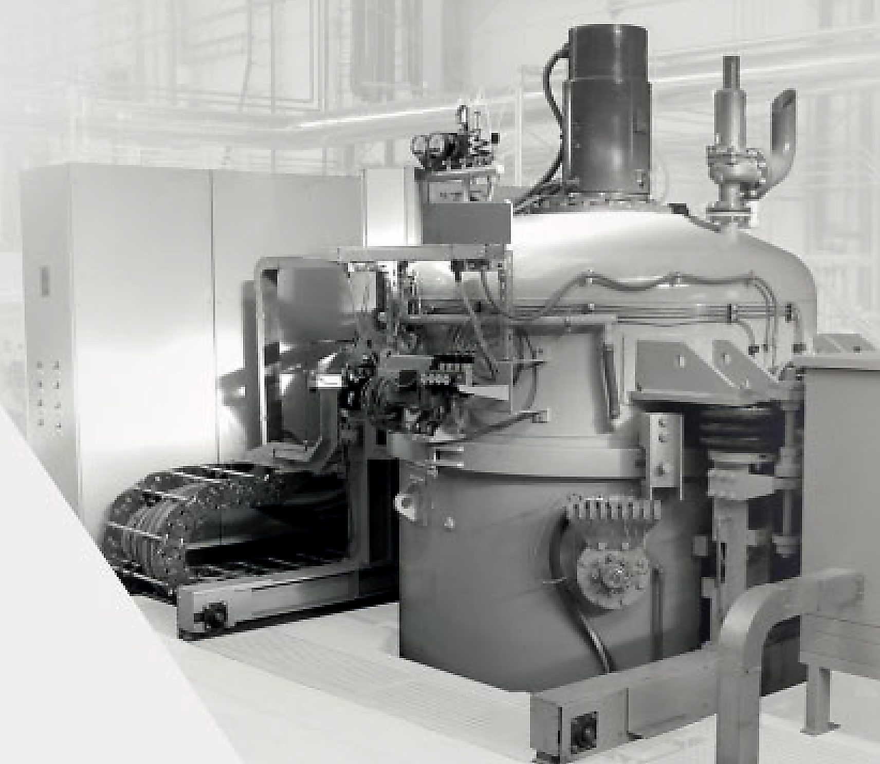
Vacuum furnaces can also be provided in multiple configurations similar to traditional atmospheric furnaces such that they can be manufactured in continuous, semi-continuous, and batch types along with horizontal and vertical configurations. As previously mentioned, in other carburizing techniques, vacuum furnace configuration also depends on manufacturing volumes, component geometry, and material grade. Vacuum furnaces can be provided with various quenching media as well. Most common LPC vacuum furnace constructions are a single chamber batch system equipped with the required acetylene LPC gas flow system and high-pressure gas quenching (HPGQ) represented in Figure 9. This furnace type is suited for alloys that have the hardenability for quenching in HPGQ. When alloy hardenability cannot be quenched in HPGQ, a multi-chamber vacuum oil quench furnace can be used. Figure 10 illustrates a horizontal multi-chamber vacuum oil quench batch furnace.
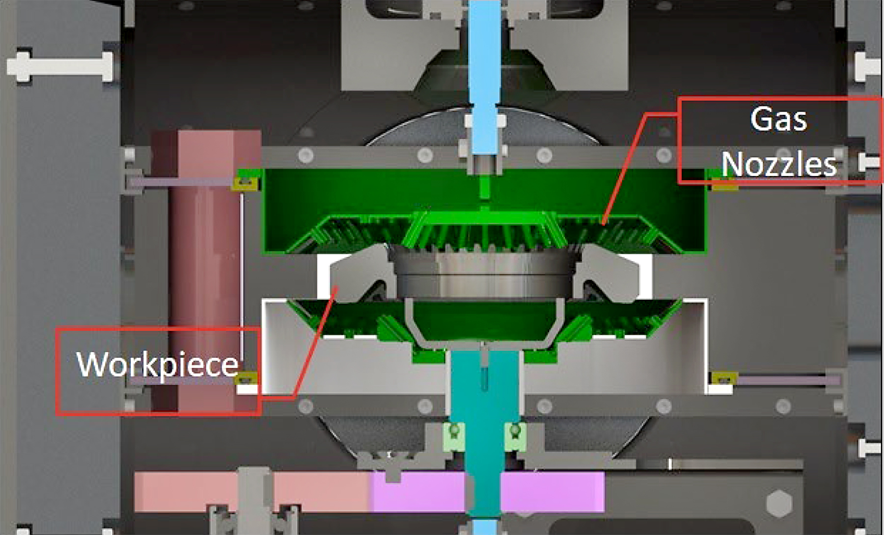
Another advantage of an LPC vacuum furnace is that horizontal batch system referenced in Figure 9 can be equipped with gas quenching at pressures up to 25 bar. Quenching pressures up to 25 bar with quenching gas distribution nozzles arranged at 360 degrees around the furnace hot zone and in the front door provide a less aggressive quench than that of oil, providing the necessary hardness, all while minimizing distortion. Figure 11 illustrates the major components of a HPGQ furnace that can include a high-power quenching blower (up to 600 HP), high efficiency heat exchanger, and an ASME certified pressure vessel to contain the required quenching gas pressure. Gasses typically used include nitrogen, helium and/or argon, depending on process requirements.

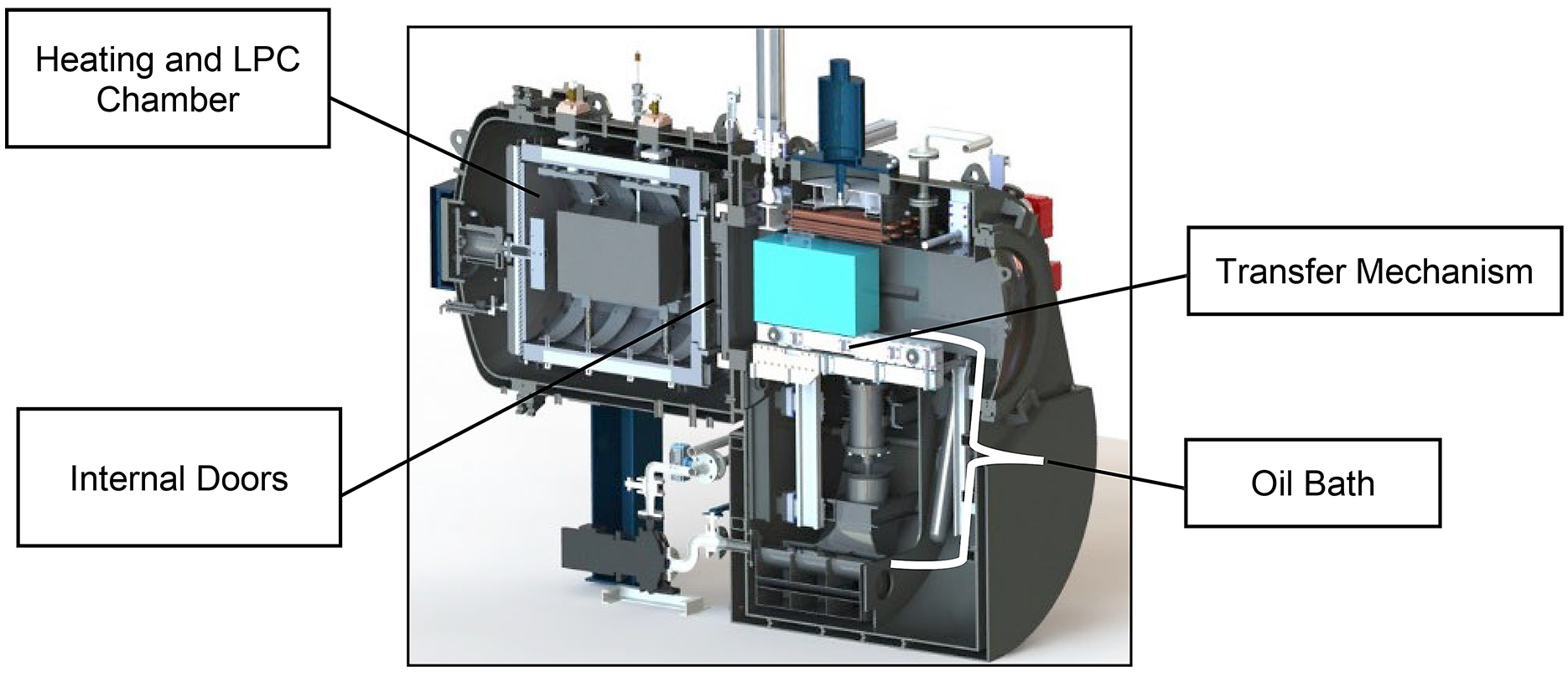
When a steel alloy requires a faster quenching requirement, an LPC system can be employed on a multi- chamber vacuum oil quench furnace. In this system, the heating chamber and quenching chamber are isolated from one another. In a double chamber solution, a charge is placed in the quenching vestibule on a transfer mechanism, and the external door is closed. Once both chambers are pumped down and oxygen is removed, the internal pressure and thermal doors are opened for charge transfer between chambers. The charge is then heated to austenization temperature and the LPC can begin. Upon the completion of the LPC process, the internal chamber doors open, and the material transfer system retrieves the charge, returning it to the oil quenching chamber and submerges the charge into the oil to complete the hardening process.
Advantages of Low Pressure Carburizing in Vacuum Furnaces
Traditional atmosphere furnaces for carburizing have limitations on maximum operating temperature due the materials used for insulating and heating. Their temperature ranges are typically limited to 1,700°F (925°C) whereas typical vacuum furnaces have temperature ratings up to 2,400°F (1,310°C). This is due to oxygen being removed from the furnace via the pumping system, thus preventing the reaction of oxygen and its degrading effects to the insulation and heating elements. With this ability of the vacuum furnace to heat past 1,700°F (925°C), carburizing cycle times can be dramatically reduced due to the steel’s ability to absorb and diffuse carbon at much higher rates. LPC provides fast, effective, efficient, uniform, and precise carburizing for regular or densely loaded charges and difficult shaped parts. The process time can be reduced up to five times depending on carburizing temperature, in comparison to traditional carburizing drastically reducing the overall processing time and utility costs.
The continuous development and advancement of LPC has brought on the implementation of sophisticated process modeling and control methods (Figure 13) allowing LPC to be a direct replacement of gas carburizing in those industries, which require case hardening of its components.
Simulation software provides the ability to develop and simulate the carburizing processes prior to running a process. The simulation algorithm performs calculations based on steel grade, temperature, size and shape of parts and carburized surface area to return the optimized sequence of carburizing and diffusion stages, as well as predicted carbon profile within the parts. The boost and diffusion sequences can be imported to the furnace recipe management system, which eliminates the potential for human error in data entry.
Advancements in automotive and aerospace designs now more than ever are looking to LPC as its go-to case-hardening solution for transmission components. Industry is placing more strict demands on material performance and, as a result, base materials are being updated to enhance their material characteristics. LPC is a perfect solution for legacy and upcoming demands, and where applicable, HPGQ can be the preferred choice of quenching media, as it brings less distortion to that of oil quenching.
Not only are there single-chamber and double-chamber vacuum furnaces, but vacuum furnaces can also be configured in various other multi-chamber solutions. Those include Figure 14 through Figure 17, which further show the advancement in carburizing.
Additional advantages of LPC in a vacuum furnace compared to traditional gas carburizing with oil quenching include:
- Decreased distortion.
- Elimination of intergranular oxidation (IGO).
- No decarburization.
- Elimination of endothermic generators.
- High productivity.
- High accuracy and repeatability of carbon penetration.
- Reduction of carburizing time.
- Lower process costs.
- Excellent case uniformity.
- Unlimited carbon transfer.
- Guaranteed process repeatability.
- No CO2 emission.
- Environmentally-friendly.
Not only do these advantages pertain to the aerospace and automotive industries, but they also apply to industries such as energy, tool and die, and medical [5].
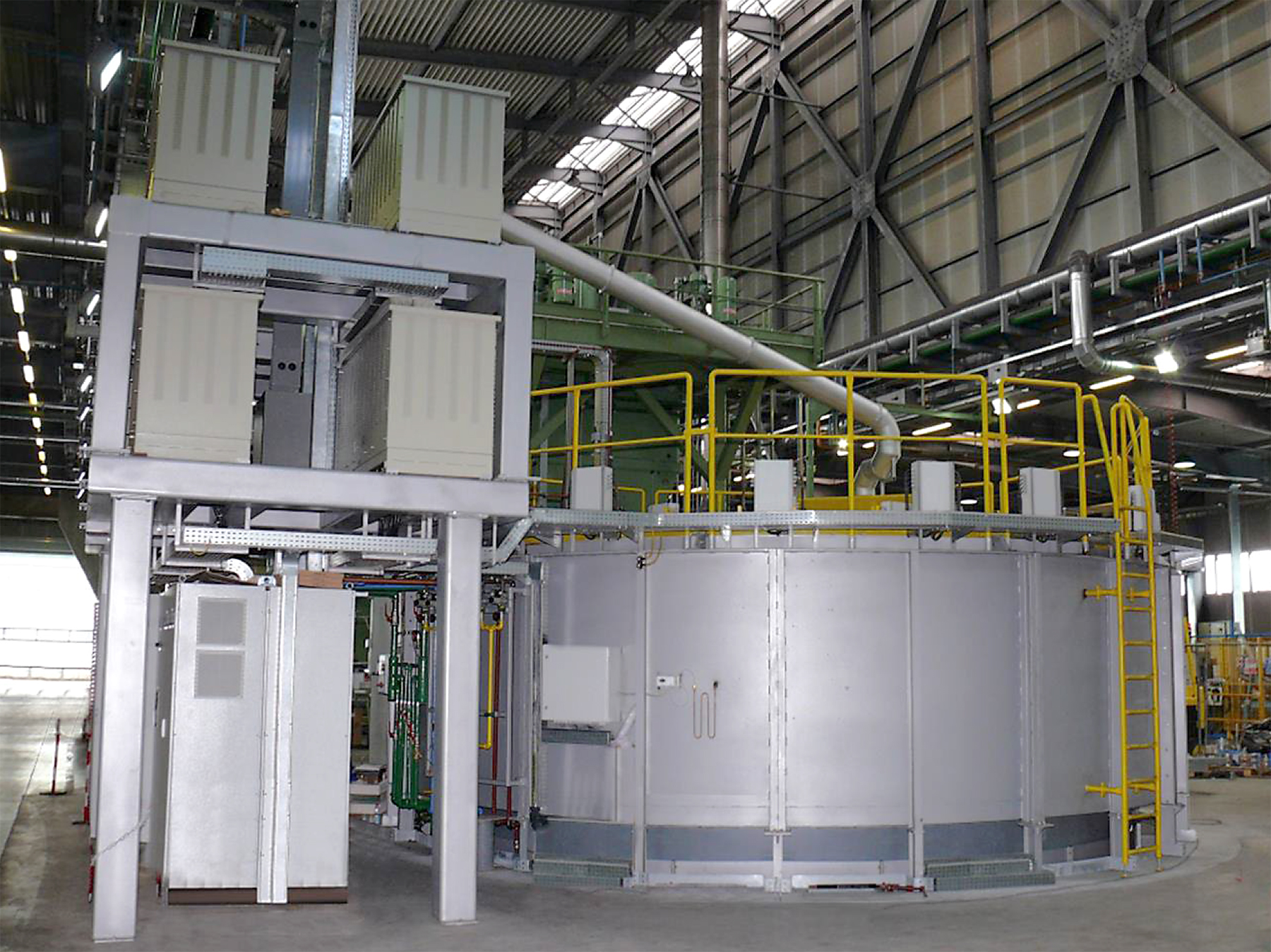
Atmosphere Pit Carburizing
Historically, atmosphere pit carburizing has been the chosen method for carburizing of large, long, and heavy work pieces. As mentioned in the introduction, this is primarily due to the pit furnace’s heavy loading capacity with tall working envelopes. The furnaces will be stand-alone systems (Figure 18) that have an accompanying quench tank next to the furnace (Figure 19).

In pit furnace systems, the load is typically supported on a fixture transported by an overhead handling system (often a crane) from material staging, then to the furnace, from the furnace to the quench tank (Figure 19) and from the quench tank to post processing such as the washing system. When transferring from the furnace to the quench tank, it provides a hazardous work environment due to the intense heat radiation being emitted from the load and fire risk if the load is quenched in an oil bath [5]. Additional and adverse problems associated with pit carburizing include:
- Long process times.
- A flammable atmosphere (endogas and methane).
- Maintenance of costly furnace components such as retorts and circulating fans.
- Furnace conditioning.
- Process monitoring (using sample coupons or continuous monitoring devices).
- Presence of intergranular oxidation.
- Furnace conditioning.
These disadvantages prove there is a need for changes to the traditional pit carburizing approach. LPC is that alternative that includes a safe working environment, no CO2 emissions, and shortened process times; however, it had not been offered pit configurations until now.
The Pit LPC Furnace System
Pit LPC provides a new and innovative approach bringing together the traditional cold wall design of a vacuum furnace with rod style metallic heating elements that are incorporated into a ceramic fiber lining, while making it possible for them to resist oxidation when exposed to oxygen at high temperatures. Note, this system does not include an alloy retort. A traditional graphite-lined vacuum furnace does not have the ability to be exposed to air as the graphite oxidizes immediately as it reacts with oxygen when at elevated temperatures. Since the Pit LPC furnace includes the necessary insulating and heating components that resist oxidation, once the LPC process is completed, the furnace can be opened (while at the LPC temperatures), and the hot load can be removed and transferred to its adjacent quench tank as illustrated in Figure 20 through Figure 22 [5]. Additionally, the furnace is equipped with a water-cooled heat exchanger and quench fan, which means a load can be slow cooled if a rapid oil quench is not required.
The furnace system reference here has the stand-alone furnace system with LPC and an adjacent quench tank and includes the following features:
Working zone of 70” (1,800 mm) diameter 120” (3,000 mm) depth.
- Gross load mass of up to 17,600 lb. (8,000 kg).
- Heating power of 360 kW.
- Maximum temperature of 2,012°F (1,100°C).
- Integrated vacuum pumping system.
- 10-2 torr (10-2 mbar) vacuum range.
- Acetylene as the carbon source gas and includes an LPC process simulator.
- To limit distortion, forced nitrogen cooling is also included for a more rapid temperature drop before quenching.
Pit LPC Case Study
To highlight the advantages in using a Pit LPC furnace system for carburizing large and heavy parts, a case study was completed on a load with the following characteristics [5]:
Mass: 13,230 lb. (6,000 kg).
Steel Grade: SAE 4820 (18CrNiMo7-6).
Desired Effective Case Depth (ECD): 0.157” (4.0mm) at 50 HRC.
Carburized Surface Area: 215 square feet (20 square meters).
Carburizing Temperature: 1,700°F (925°C).
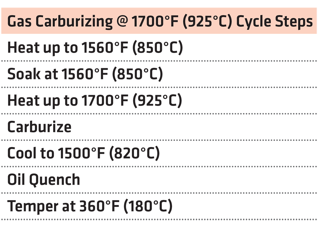
This load was simulated in both a gas-carburizing cycle in a traditional atmosphere pit type furnace and LPC in the Pit-LPC system. The comparison is based on both an atmosphere gas carburizing furnace at a plant and LPC data retrieved in the laboratory Pit Style-LPC furnace. The steps used in the gas carburizing cycle are shown in Table 1.
In contrast to the base atmospheric carburizing process, an LPC process was simulated at two different temperatures to understand the effect of carburizing temperature on the cycle time. The corresponding LPC cycle steps are shown in Table 2 for 1,800°F (980°C) and Table 3 for 1,900°F (1,040°C).
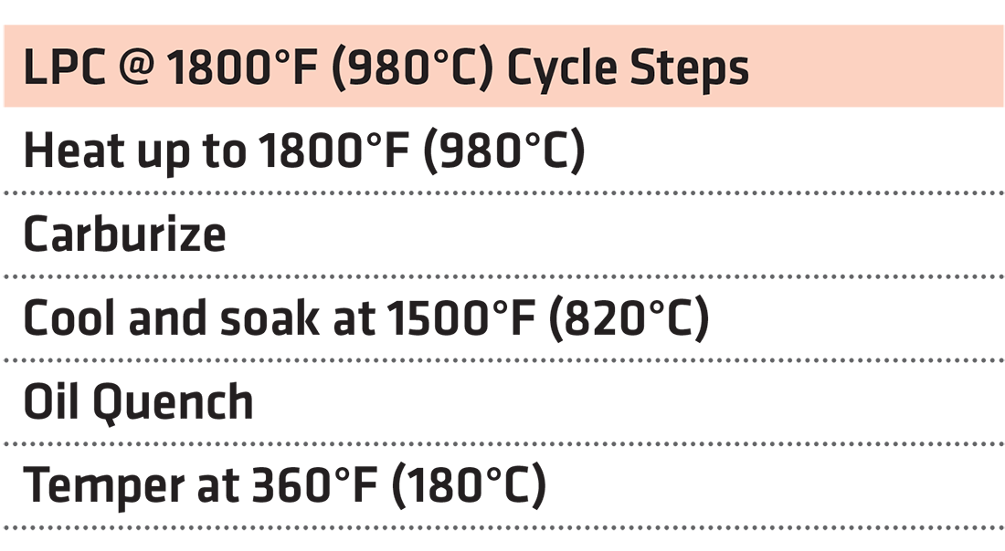

Table 3 then shows the LPC cycle steps used at 1,900°F (1,040°C).
Pit LPC Case Study — Results and Analysis
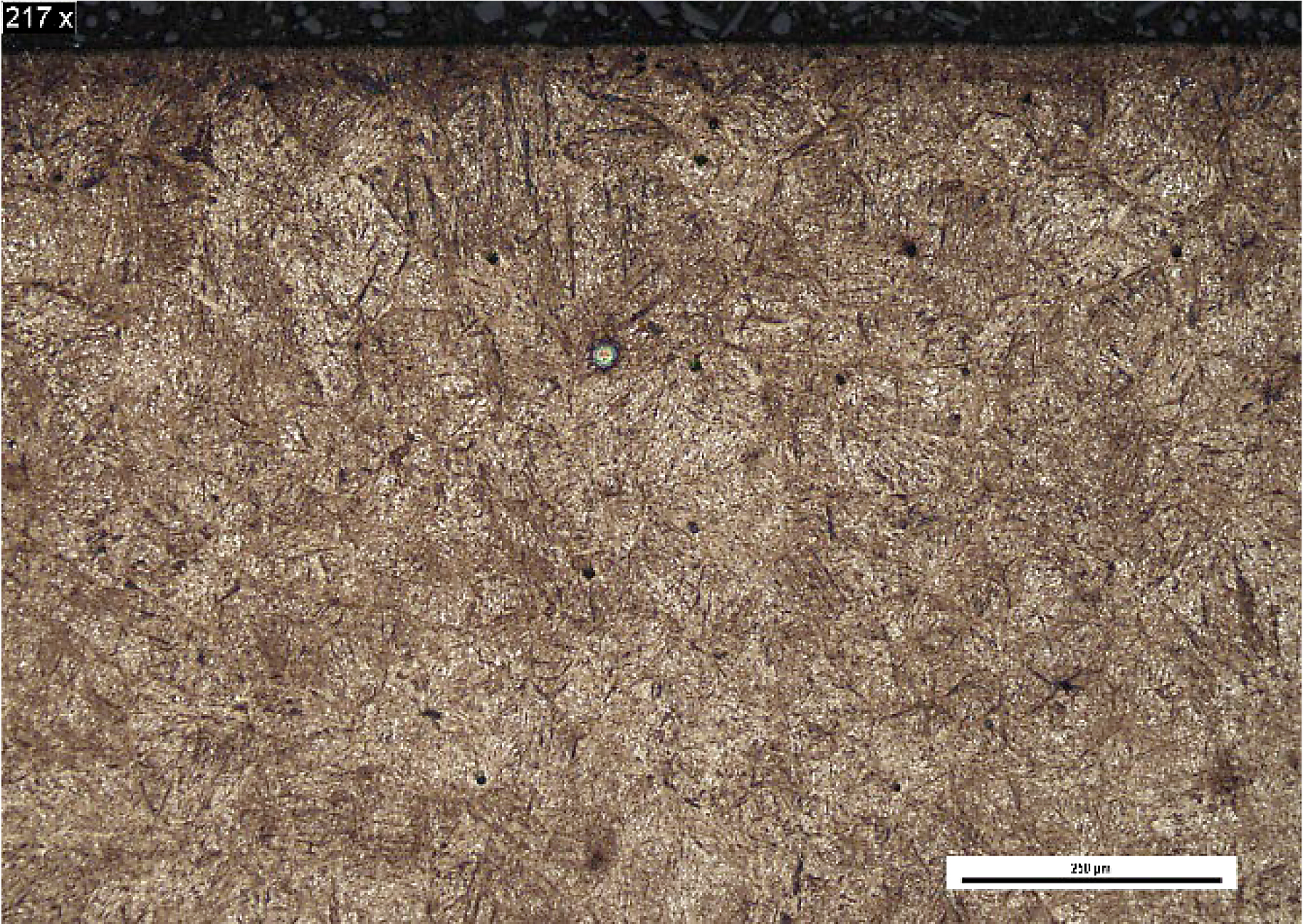
All three carburizing processes were combined with an oil quench and temper where all three processes yielded similar metallurgical results. The micrograph in Figure 23 illustrates the resulting structure that is martensite with approximately 10 percent retained austenite [5].
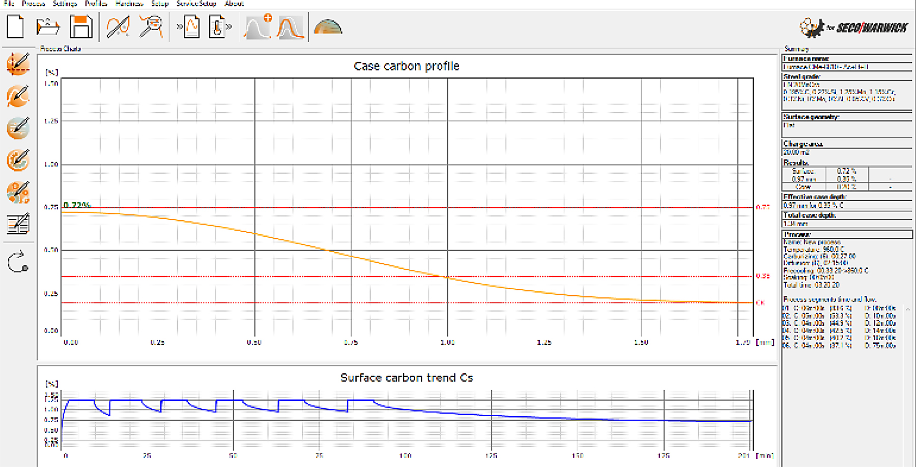
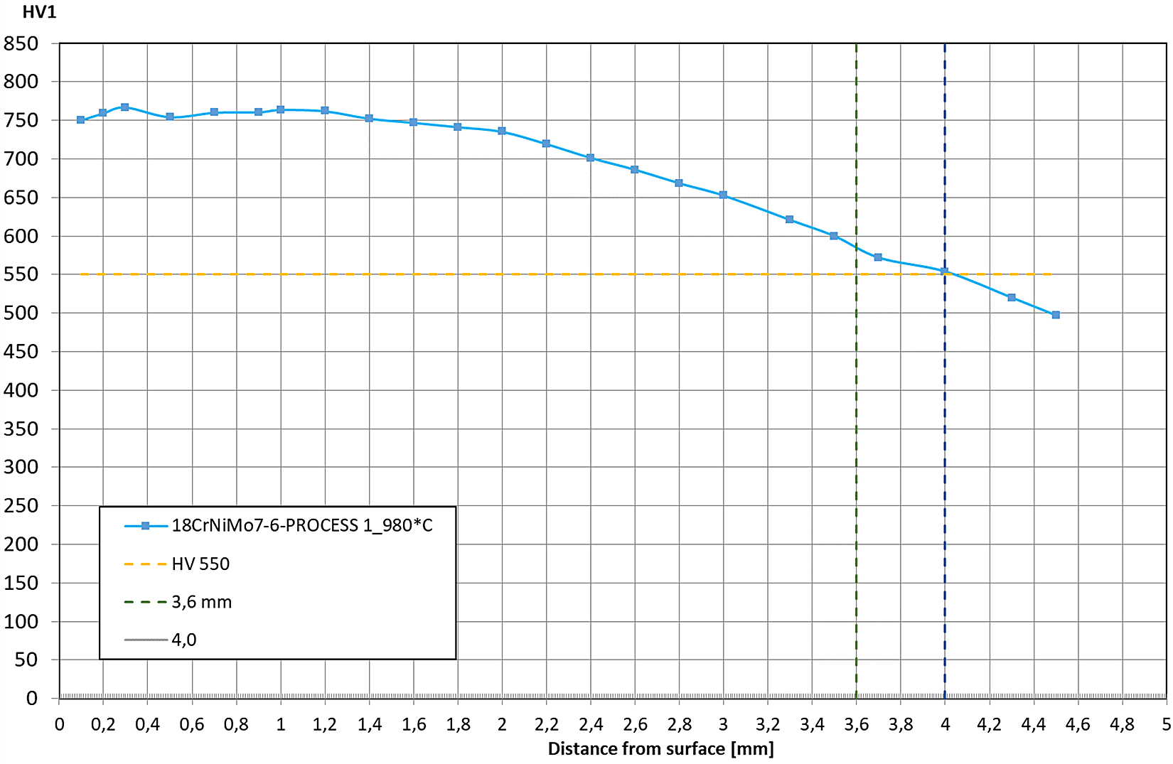
The microstructure shown in Figure 23 is paired with the hardness profile measured on Figure 24 and shows the surface hardness reached nearly 62 HRC (770 HV) and ECD was 0.157” (4 mm) as defined by a 52.5 HRC (550 HV). Noteworthy, the grain size maintained appropriate ASTM size of 7. This profile was the result of the 1,800°F (980°C) LPC process [5].
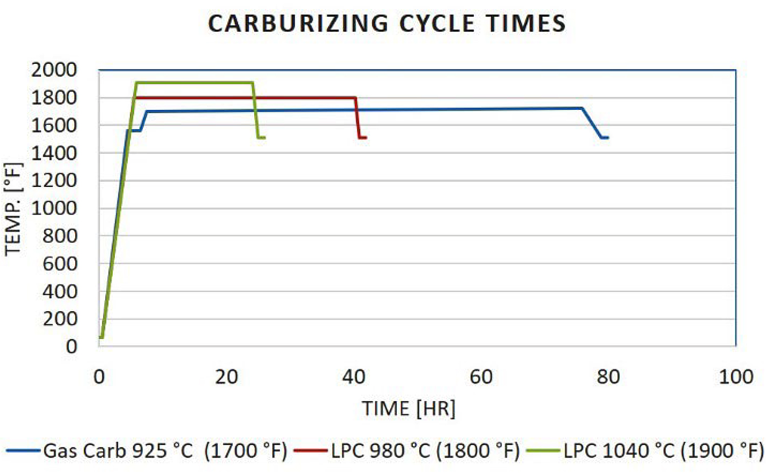
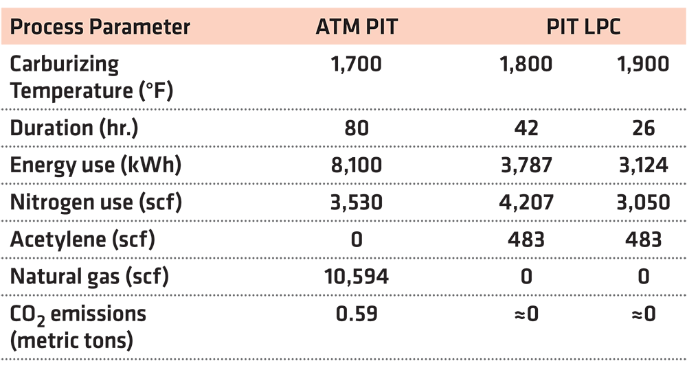
To reach the hardness profile shown in Figure 24, the cycle profile is represented in Figure 25 (1,800°F). It is important to note that gas carburizing conducted at 1,700°F (925°C) cycle requires nearly 80 hours to complete. Meanwhile, LPC conducted at 1,800°F (980°C) required only 42 hours to complete, which is almost a 50 percent reduction. A further increase in carburizing temperature to 1,900°F (1,040°C) reduced the time to 26 hours, which is a 68 percent reduction, Figure 25 (1,900°F).
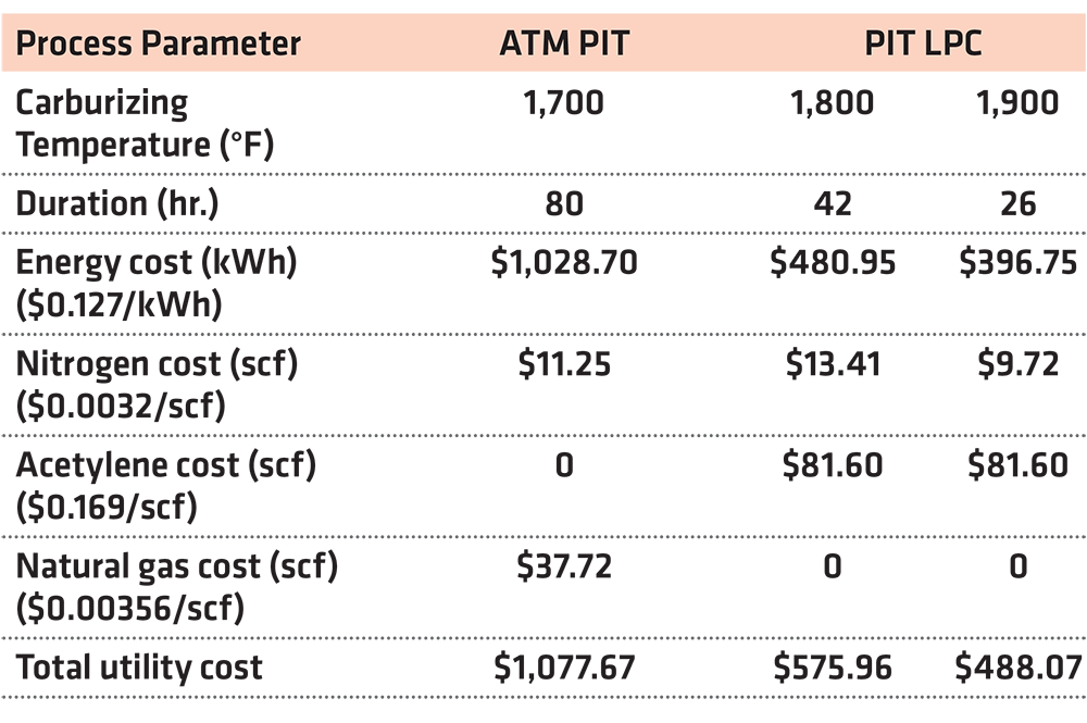
The reduced cycle time produced by the Pit Style-LPC drastically reduced the utility consumption while eliminating carbon dioxide and carbon monoxide emissions. The utility consumption in Table 4 shows an energy savings of 53 percent when LPC is employed instead of atmosphere gas carburizing. As such, when increasing the carburizing temperature while using LPC results, the end result proved to show increased savings of 61 percent. It is important to note that LPC eliminates the need for natural gas and the corresponding CO2/CO emissions. The corresponding cycle utility costs shown in Table 5 shows that switching to LPC has the potential of a 47 percent savings. An increase in the LPC temperature yields an even higher savings of 54 percent [5].
Impressive cost savings are not the only benefit to the Pit Style-LPC. Time savings also resulted in increased productivity vs. gas carburizing. When evaluating a five-day operating week, the Pit Style LPC unit has the potential to be drastically more productive. If carburizing at 1,800°F (980°C), the reduction in cycle time has the possibility to nearly double the total number of annual cycles. When evaluating carburizing at 1,900°F (1,040°C), this triples the annual number of cycles. Table 6 shows the increase in productivity and the accompanying savings per cycle [5].
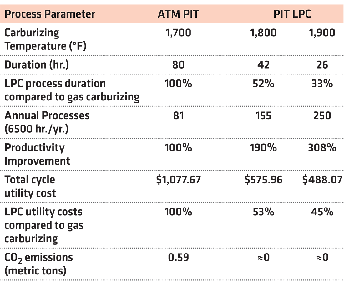
To further illustrate the Pit LPC savings compared to atmosphere carburizing, the Pit LPC system has availability of 6,500 hours annually. At 1,800°F (980°C) 155 cycles are achievable in one Pit LPC furnace, in contrast to the gas carburizing process, which requires two atmosphere pit furnaces. The total processing cost would amount to $166,782, while the Pit-LPC costs would only be $89,136. This is a total savings of $77,646.
Moving to the higher carburizing temperature 1,900°F (1,040°C), 250 cycles are achievable in one Pit LPC system, compared to three atmosphere pit furnaces for the same demand. Meanwhile, the annual cost savings increases to $147,400. Table 7 summarizes the data behind this process savings.

Conclusions
Pit LPC is a new and revolutionary furnace system that is a drop-in replacement for traditional atmosphere pit carburizing solutions. This approach can handle the same large and/or long loads with deep ECD while reducing the process time and utility costs. These benefits drastically increase the ROI when converting from atmosphere carburizing to LPC while eliminating carbon emissions associated with gas carburizing.
Bibliography
- ASM International Handbook Committee, ASM Handbook Heat Treatment, Vol. 4, 1991
- Herring, D.H. “The History of Vacuum Carburizing: 1968-Present.” Process and Controls Training, 20-22 August 2019, SECO/WARWICK Corp., Meadville, PA
- Herring, D.H. “Atmosphere Heat Treatment: Atmosphere | Quenching | Testing” Vol.2. Troy, MI., BNP Media II, 2015.
- ASM International, Materials handbook; Heat Treating, Cleaning and Finishing, 8th Edition”, Vol. 2, 1964
- Marteeny, D. “Vacuum Carburizing in a Pit Style Furnace: A 21st Century Solution to Large Component Case Hardening” ASM International, 2021
- Marteeny, D. “Hardening 4.0: An Evolution in Quenching Explained.” Industrial Heating Webinar. 4 June 2020. www.industrialheating.com/events/1192-hardening-4-0-an-evolution-in-quenching- explained.
- Hart, T. “True Single Piece Flow Case Hardening for In-line Manufacturing.”, ASM Heat Treat Show 2017, 24-26 October 2017, Greater Columbus Convention Center, Columbus, OH.
Printed with permission of the copyright holder, the American Gear Manufacturers Association, 1001 N. Fairfax Street, Suite 500, Alexandria, Virginia 22314. Statements presented in this paper are those of the authors and may not represent the position or opinion of the American Gear Manufacturers Association. (AGMA) This paper was presented October 2022 at the AGMA Fall Technical Meeting. 22FTM09


 general practice for CQI-9 and AMS2750E")


