


A large part of the misunderstanding of induction hardening seems to stem from an incomplete grasp of the basic induction heating process. This is surprising, as the process itself is relatively easy to grasp once certain fundamental steps have been explained. Induction heating is quite literally heat that has been induced in a workpiece. Roughly put, this effect is achieved by surrounding the workpiece (or the part of the workpiece to be heated) with a copper coil. An alternating current is then fed through the coil, generating a magnetic field. The strength of the field varies in relation to the strength of the current. The field is concentrated in the area enclosed by the coil, while its magnitude depends on the strength of the current and the number of turns in the coil (Figure 1).
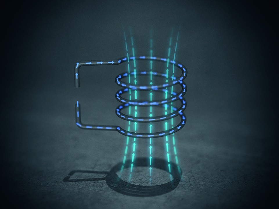
Eddy currents are induced in any electrically conductive object—a gear, for example—placed inside the coil. The phenomenon of resistance generates heat in the area where the eddy currents are flowing. Increasing the strength of the magnetic field increases the heating effect. However, the total heating effect is also influenced by the magnetic properties of the object and the distance between it and the coil (Figure 2).
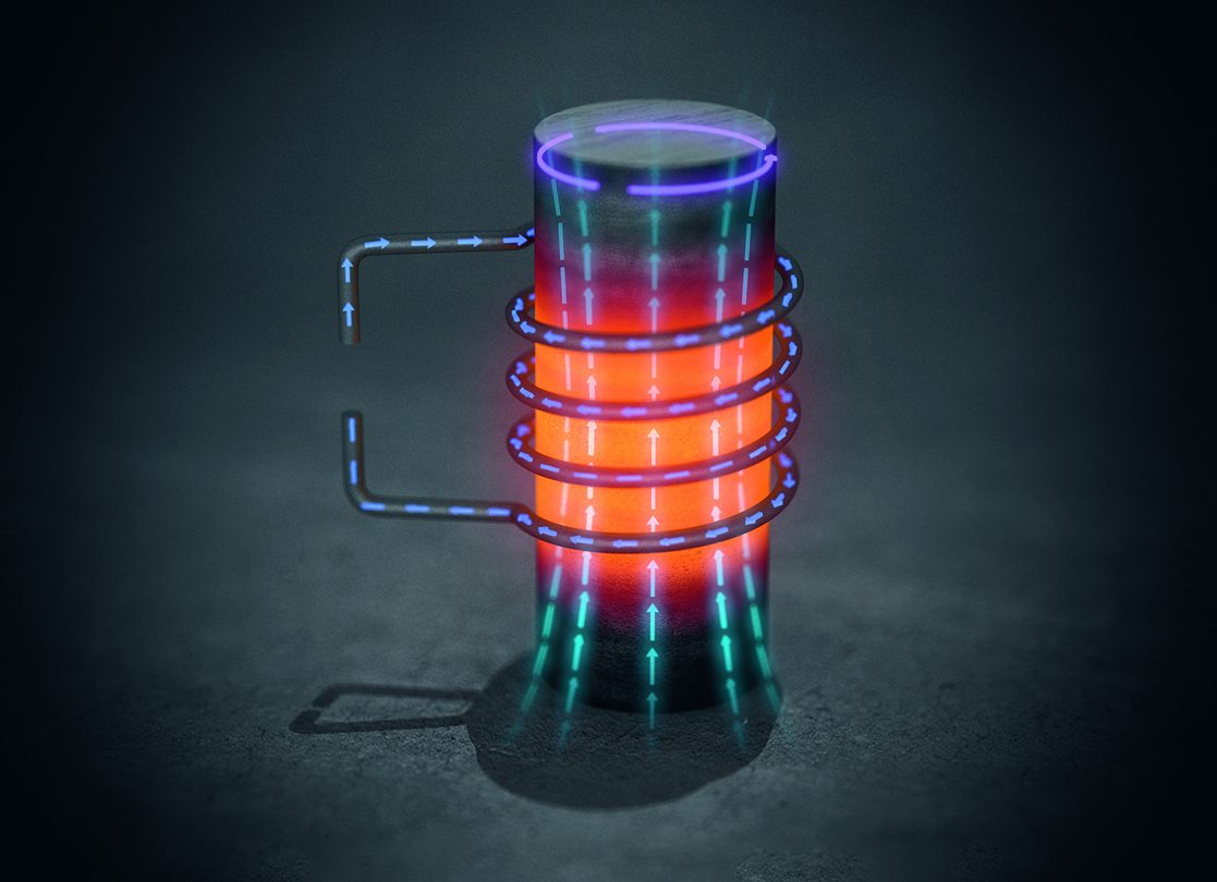
The eddy currents create their own magnetic field that opposes the original field produced by the coil. This opposition prevents the original field from immediately penetrating to the center of the object enclosed by the coil. The eddy currents are most active close to the surface of the object being heated, but weaken considerably in strength towards the center (Figure 3).
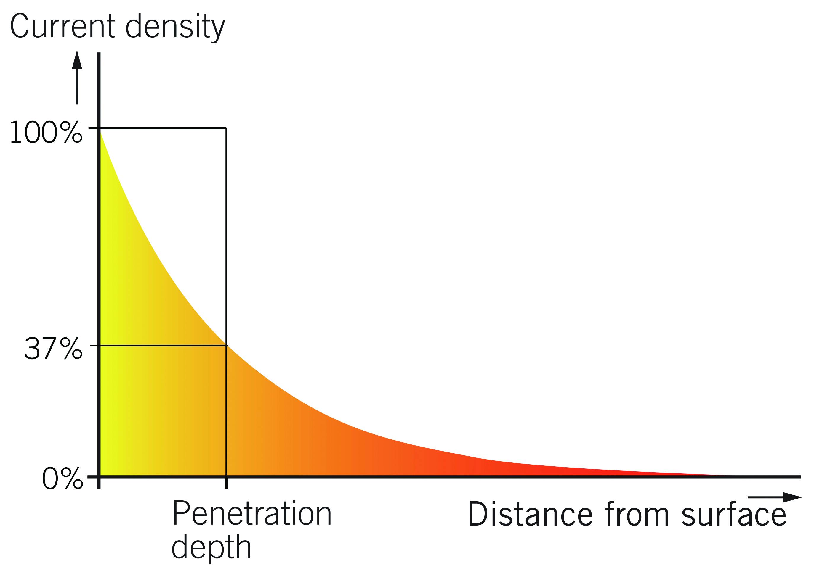
The distance from the surface of the heated object to the depth where current density drops to 37% is the penetration depth. This depth increases in correlation to decreases in frequency. It is therefore essential to select the correct frequency in order to achieve the desired penetration depth.
Cost-Cutting Advantage
Induction is the cost-cutting alternative to furnace case hardening of small- and medium-sized gears. Key features of induction hardening are fast heating cycles, accurate heating patterns, and cores that remain relatively cold and stable. Such characteristics minimize distortion and make heating outcomes extremely repeatable, reducing post-heat processes such as grinding. This is especially true when comparing induction hardening to case carburizing.
Induction hardening also reduces pre-processing, as the geometry changes are less than those caused by carburizing. Such minimal changes mean distortion does not need to be accounted for when making the gear. With gears destined for gas carburizing, however, “offsets” that represent distortion are often introduced at the design stage. These intentional offsets compensate for distortion caused during the lengthy heat soaks typical of carburizing.
Induction can heat precisely localized zones in gears. Achieving the same degree of localized hardening with carburizing can be a time- and labor-intensive procedure. When carburizing specific zones such as the teeth areas, it is usually necessary to mask the rest of the gear with “stop off” coatings. These masks must be applied to each workpiece, and removed following the hardening process. No such masking is necessary with induction hardening.
Induction hardening is ideal for integrating into production lines. Such integrated inline hardening is more productive than thermo-chemical processes. Moreover, integrated hardening minimizes costs, as the gears do not have to be removed for separate heat treatment. In fact, induction heating makes it possible to create one seamless production flow through the machining, hardening, quenching, tempering, and storage stages.
For Smaller Dimensions
Inductive gear hardening can be divided into two main areas: partial and spin.[1] The former is when specific parts of the gear such as the tooth profile or gaps are hardened one-by-one using a customized shaped coil. This method is usually used on large gears such as those employed in wind turbines, earth movers, and so on. Spin hardening, which is typically used on medium- and small-dimensioned gears, involves placing the entire gear within a coil. The workpiece then spins around while a current is fed through the coil, inducing heat in specific areas. Spin hardening can in turn be divided into alternatives: through hardening and contour hardening (Figure 4).
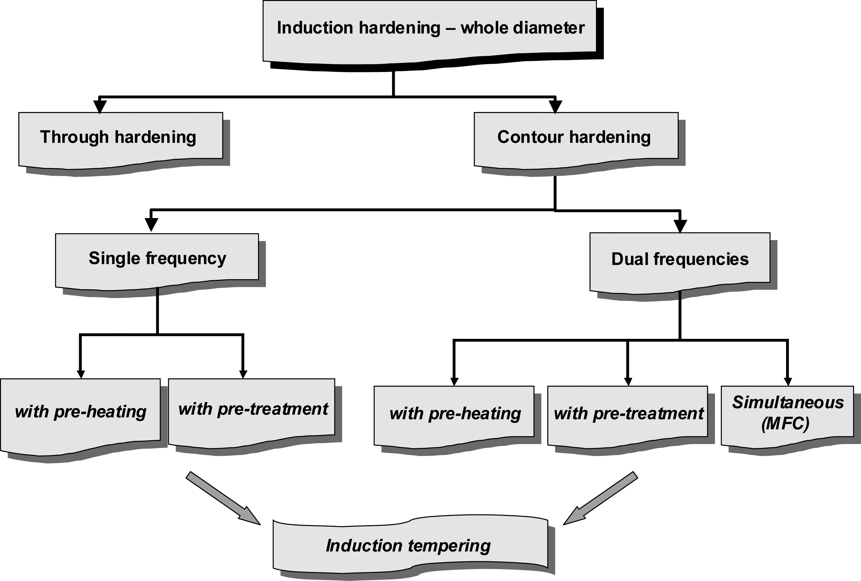
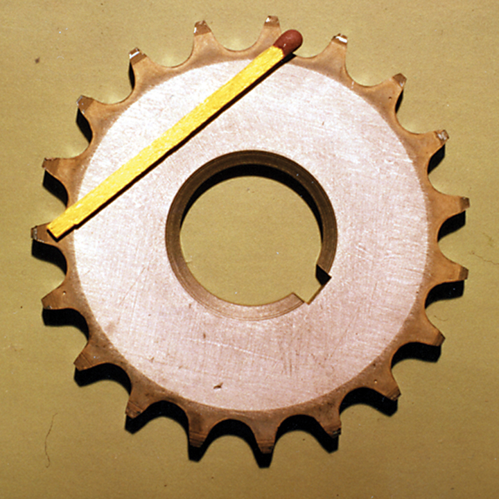
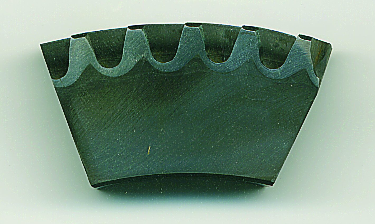
With inductive through hardening — used primarily for gears exposed to high wear — the tooth perimeter is hardened with a low specific power.[2] However, if the frequency is too low, there is the risk that above the Curie temperature the induced eddy current flows mainly in the root circle, and the temperature lags behind in the teeth. Quenching is either by submersion or spraying, and is usually delayed in order to achieve a uniform temperature between the teeth and the root circle.[3] Tempering after through-hardening is essential in order to prevent later cracking (Figure 5).
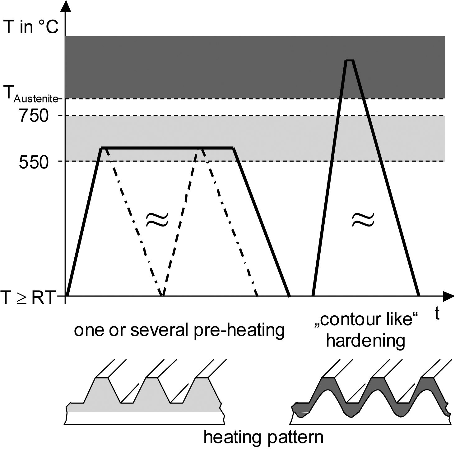
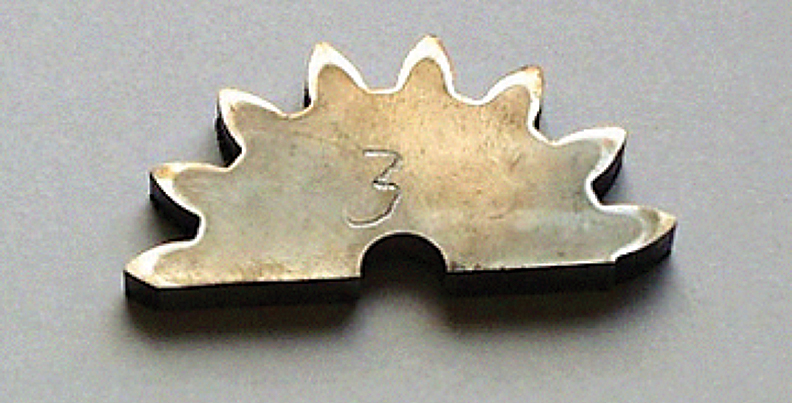
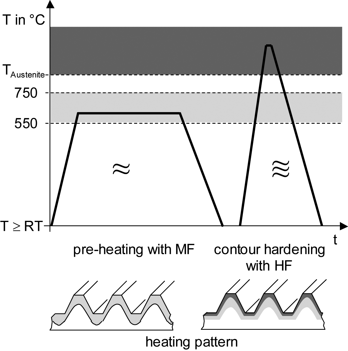
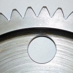
Contour hardening is divided into single- and dual-frequency processes. With the former, a single generator feeds the inductor. Austenitizing is achieved either in a single heating, or by pre-heating the gear to 550-750°C before heating it to the hardening temperature. The purpose of pre-heating is to reach an adequately high austenitizing temperature in the root circle during final heating, without overheating the teeth tips. Short heating times and a high specific power are usually required to achieve hardening profiles at an irregular distance to the tooth face (Figure 6, Figure 7, Figure 8).
Accurate Monitoring Needed
Dual-frequency (also known as multi-frequency) hardening represent one of the most exciting uses of induction technology for the gear industry, as the method delivers consistent and predictable results for gears with complex geometries. It is however important to remember that the terms “dual/multi frequency hardening” refer to two processes: separate (or stepped), and simultaneous. The first, which achieves results similar to case hardening, involves applying two different frequencies one after the other to the gear. The teeth are first pre-heated at a low frequency to 550-750°C. The frequency should be such that pre-heating occurs in the root circle area. After a short delay, use of a higher frequency and specific power achieves austenitizing (Figure 9).
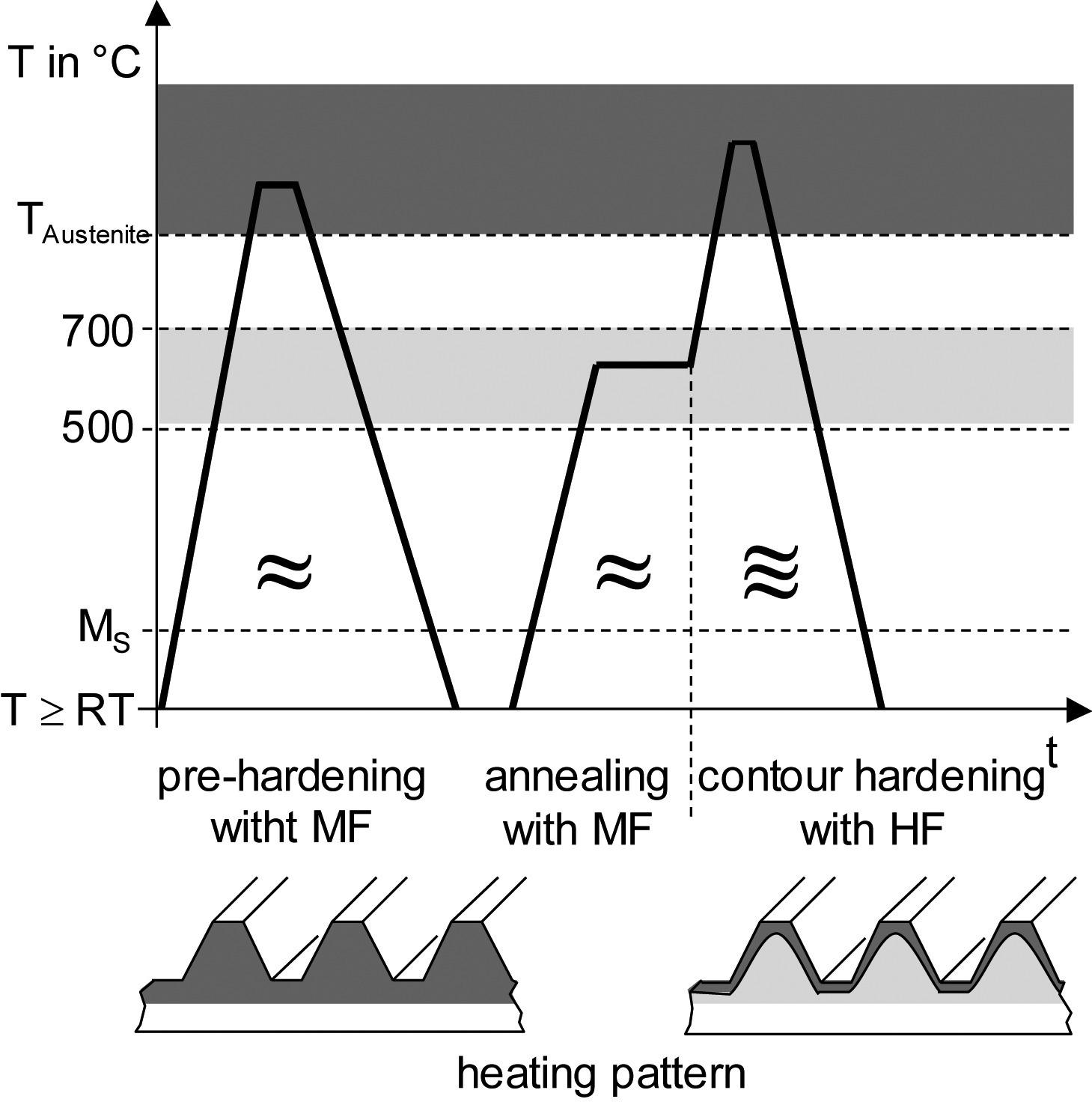
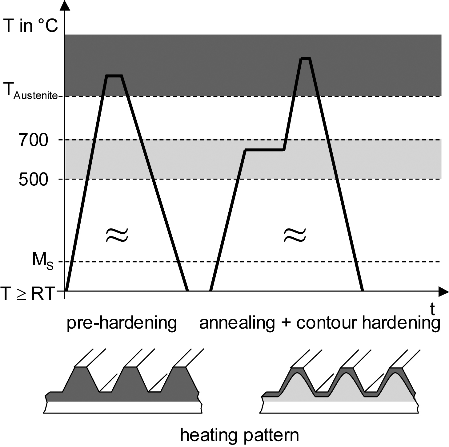
Accurate monitoring systems are essential, as heating times are measured in tenths of seconds or seconds during this final heating phase.[4] Due to the high demands on the hardenability of the material in contour hardening, tempering of the tooth area before hardening may be considered as an alternative process (just as in single-frequency contour hardening (Figure 10).
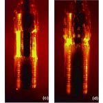
With the simultaneous dual-frequency method, a lower and a higher frequency feed into the inductor at the same time. Hardening is achieved by heating the root circle with the lower frequency, and the tooth tips with the higher (Figure 11).
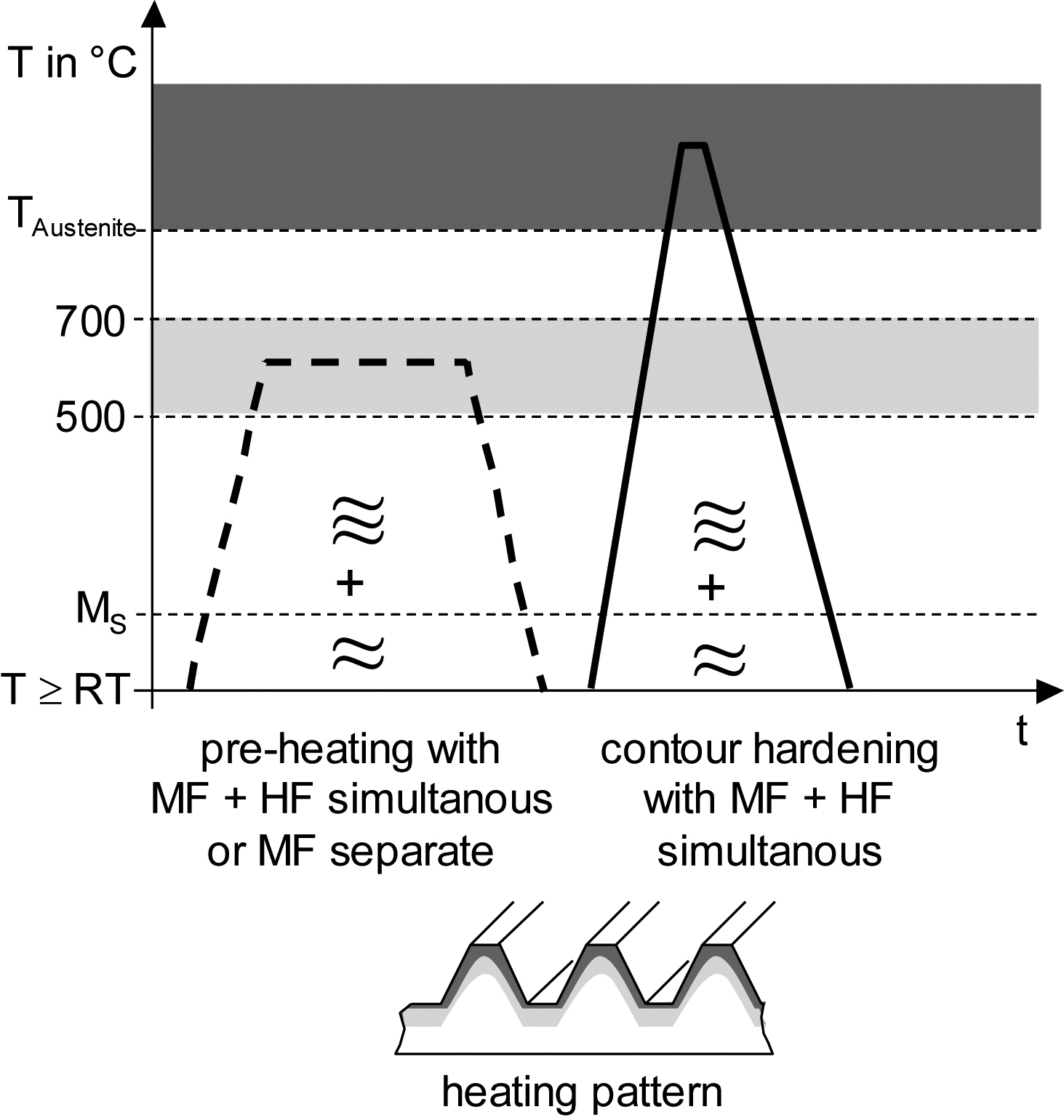
Unlike the separate / stepped process, pre-heating is not always required when using the simultaneous dual-frequency process.[5] However, the short heating times used with simultaneous frequencies place high demands on the generator and machine engineering. An example of a hardening profile achieved with this method can be seen in Figure 12.
Versatile and Reliable
Correct quenching is critical for perfect spin hardening results, and should be performed as soon as possible after the final heating. The time gap between heating and quenching can be minimized by using a fast CNC axle to position the spray head, or by integrating a quench into the inductor. During the quenching phase, the rotational speed of the gear is decreased to below 50 rpm to avoid a “shadow effect” on the flank opposing the direction of rotation.
Many other factors influence spin hardening outcomes. The material to be hardened and its initial structure, for example, have a decisive impact. Due to short austenitizing times, the initial steel structure must be close-grained (ASTM 7 and above). Non-homogenous pearlite-ferrite initial structures are not suitable. The importance of initial structure and carbon content increases as module size decreases. If a somewhat increased quenching distortion is acceptable, tempering prior to contour hardening can greatly improve the gear’s hardenability.
Module size is another key factor in spin hardening. For the dual frequency method with simultaneous frequencies, the range is 1.8 < m ≤ 5mm. However, for cost reasons the gear diameter should be limited to approximately d ≤ 250mm. For modules of m ≤ 3.0mm, the separate dual frequency method is preferred. This is because a final hardening phase with only the higher frequency achieves better hardening at an irregular distance to the face.
Spin hardening is a versatile and reliable process that can harden spur-toothed, helical spur, and internal gears at an irregular distance to the face. However, different gear forms influence hardening results. With helical gearing, an asymmetrical hardening of the tooth flank at a depth of up to 2-3mm from the gear face has to be accepted.[6] This situation is however only pronounced with helix angles of β ≥ 28° (Figure 13). Patented coil solutions are available that limit this effect by enhancing power distribution.
References
- Benkowsky, G. Induktionserwärmung (213-227). VEB Verlag Technik Berlin, Berlin (1980).
- Weiß, T. “Zum Festigkeits- und Verzugverhalten von randschichtgehärteten Zahnrädern.” Dissertation Technische Universität München (1983).
- Specht, F. “Induction Heat Treating Off-Highway Components.” In Heat Treating Progress (22-25), Volume 3, Number 2, March 2003.
- Marquis, F. “Traitment thermique par induction, suivi de qualité en temps reel.” Traitment Thermique (23-27) 368, Janv.-Fév. (2006).
- Schwenk, W., Peter, H.J. “Anwendungen des Zweifrequenz-Simultan-Verfahrens zum induktiven Randschichthärten.” Elektrowärme Internationl, Heft 1 (13-18), März 2002 (2002).
- Möckel, F., Werner, J. “Praktische Erfahrungen beim Induktivhärten schrägverzahnter Bauteile.” Neue Hütte, 26 (391-92) (1981).


 general practice for CQI-9 and AMS2750E")


