


Careful selection and installation of temperature sensors can ensure accurate sensor performance, which in turn improves product quality and production efficiency.
1: Select the Correct Sensor Assembly for the Application
This may seem self-evident, but it is surprising how often process efficiency is hampered by using the wrong thermocouple type. Factors such as time at temperature, degree of accuracy, thermal cycling rate, and environment may affect the selection of the best thermocouple type to produce accurate, reliable, long-term performance.
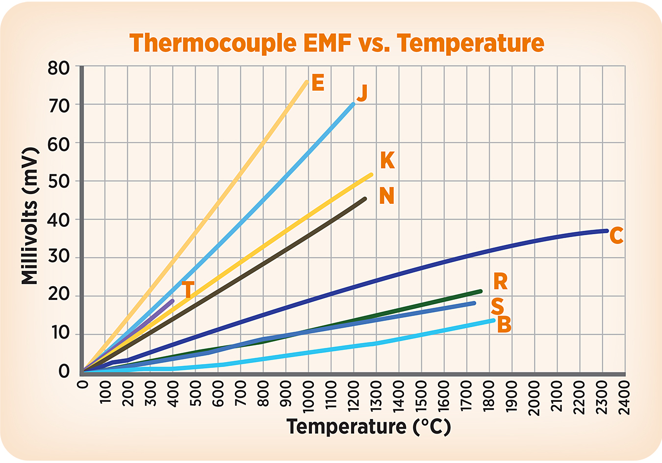
For most applications with operating temperatures of 1,400°F (760°C) or less, any of the base metal calibrations (J, E, T, and K) will function, but all are not created equal.
Type J offers the widest range of environments, including vacuum, oxidizing, reducing, and inert atmospheres over the temperature range of 32°F to 1,400°F (0°C to760°C). Above 1,000°F (538°C), however, the iron leg is susceptible to rapid oxidation, and below 32°F, the iron experiences rusting and embrittlement.
Type T is preferred for lower temperatures, including subzero (-330°F [minus-201°C]), and is resistant to corrosion in moist atmospheres. In air or oxidizing atmospheres, however, oxidation of the copper thermoelement occurs at temperatures above 700°F (370°C).
Type K is a good choice for oxidizing and inert atmospheres up to 2,300°F (1,260°C). With better oxidation resistance than Type E, J, and T, Type K thermocouples often are used at temperatures above 1,000°F, although they are subject to green rot corrosion at temperatures above 1,500°F (815°C) in low-oxygen environments. Type K thermocouples are not recommended for use in reducing atmospheres or atmospheres that alternate between oxidizing and reducing, in sulfurous atmospheres, or under vacuum conditions.
Type N is becoming more popular over time as a replacement for Type K. Type N has the same temperature range, is comparable in price, but does not suffer from the order-disorder temperature drift or green rot that can affect Type K thermocouples.
Type E exhibits the highest sensitivity of the base metal thermocouples and often is selected for this feature. These thermocouples function well in a broad temperature range from minus-330°F to 1,600°F (minus-201°C to 870°C) in oxidizing or inert atmospheres. They also successfully resist corrosion in high moisture environments. Type E thermocouples are not recommended for reducing or vacuum atmospheres.
The noble metal thermocouples (S, R, and B) and Type C are the best choice for very high temperatures or to increase long term accuracy and repeatability, though they are more expensive.
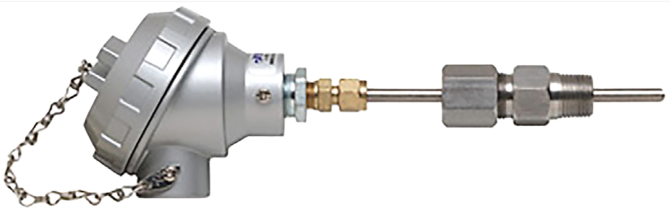
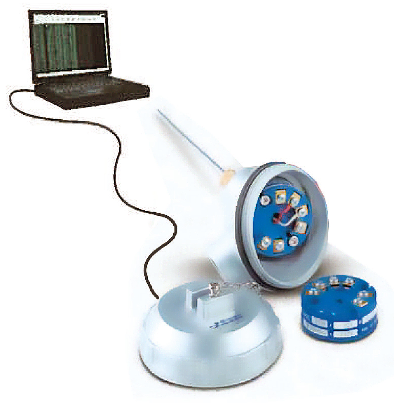
Selecting the thermal element is not the only consideration. Careful selection of insulation materials and sheath materials and being certain of how these materials may interact with each other is also critical. Consult with your sensor manufacturer, providing all the details about your application environment, to ensure you select the best assembly for your needs. (Figure 1)
2: Ensure Adequate Immersion Length
One of the most common errors made in configuring a temperature sensor is not providing adequate immersion length. In a process pipe application, the sensor should extend into the process a minimum length equal to one-third the inside diameter of the pipe, with the optimum location at the center of the pipe diameter. When calculating this distance, be sure to add enough length to account for pipe and mounting flange thicknesses.
Another consideration is stem conduction. This refers to unwanted heat transfer up the metallic sheath of the thermocouple. To compensate for this, use a minimum immersion length of seven to 10 times the diameter of the probe. Keep in mind that use of a thermowell will magnify the stem conduction effect.
3: Maximize Sensor Response Time by Reducing Mass
Sensor material mass equates to sensor speed of response. Lower mass yields faster sensor response. Most oven and furnace applications do not require meaty-sized sensor elements as the environments generally are benign and sensor sheathing is not needed. Use of thermowells and pipewells offers physical strength but increase mass, slowing sensor reaction time. In addition, bare junction thermoelements respond faster than closed-sheath elements of equal size. This is particularly important to consider during thermal ramp and cool time, as excessive material mass will hamper the sensor’s ability to keep track of the rapidly changing temperature.
4: Lower-Than-Expected Readouts May Indicate Poor Construction
Another common problem in sensor performance is seeing a lower-than-expected output from the sensor. At low temperatures (less than 250°F [121°C]), this may indicate thermal shunting due to degradation of the cold-end seal. To check for this, measure the insulation resistance of the ungrounded thermocouple between the lead wires and the metallic sheath. The insulation resistance should be greater than 1 x 10⁹ Ω at 500 VDC. Thermal shunting at lower temperatures also may be caused by moisture penetration of the cold-end seal.
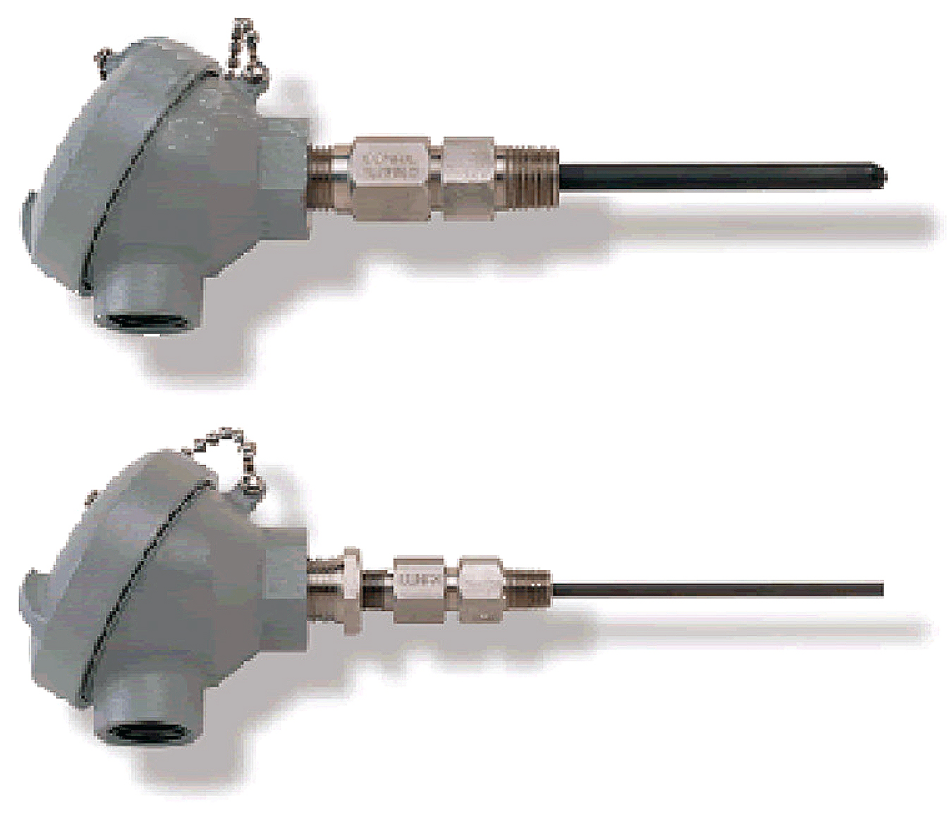
Poor termination practices are another source of low readings. Stripping the lead wire too far or improperly applying insulation can permit moisture and contaminants to shunt the thermoelements, creating low insulation resistance. This can be corrected easily by cleaning the terminal blocks and ensuring the insulation material covers all exposed wires except the portion immediately under the terminal screw heads. (Figure 2)
5: Use the Proper Lead wire
Extension-grade wire offers a more restricted temperature range than thermocouple-grade wire. The extension wire generally follows the EMF/temperature curve as the thermocouple wire to a certain temperature, then veers significantly. If you use extension-grade wire beyond its limitations, you may introduce a significantly large error into your readings.
For reliable readings, the thermocouple wire in the terminal head must be connected to the same thermocouple type wire all the way to the instrumentation that performs the cold junction compensation (readout, PLC, transmitter, etc.). Simply twisting signal wires together in the terminal head should be avoided, and use of a proper screw-type terminal block will provide long-term interconnection and avoid signal degradation over time due to poor connection and corrosion issues. For Types C, R, S, and B, running thermocouple-grade wires would be prohibitively expensive, so proprietary alloy wires have been developed for use with these materials.
A common cost-saving scenario is to use copper wire rather than extension wire, but copper does not follow the EMF/temperature curve of thermocouples at all and, therefore, introduces a significant degree of error. The exception to this is Type B thermocouples, which may use copper/copper wire up to 212°F (100°C). (Figure 3)

6: Protect Against Radio Frequency Interference
Thermocouple conductors with extension wire are sensitive to external electrical “noise” produced by handheld radios, circuit breakers and electrical relays, welding machines, variable speed motors, fluorescent lights, and other magnetic field generators. If running lead wires near power lines or other noisy signals, the lead wires should cross perpendicular and not run parallel to these lines. Numerous methods eliminate the detrimental effects of noise interference. One of the simplest is to use an ungrounded, rather than grounded, thermocouple in conjunction with twisted shielded lead wire. If the lead wire has a conductive over-braid or is run inside of conduit, the braid or conduit should be grounded on one end. Grounding at both ends will cause a ground loop and further compromise the signal.
Another is to properly secure all enclosure covers and run the cable through a metal conduit. Finally, a 4 to 20 mA signal conditioner can be located at — or as close as possible to — the thermal element. The milliamp signal is much less susceptible to interference than the extremely low voltage from the sensor.
7: Properly Install Surface Mount Sensors to Improve Accuracy
Surface mounting is an easy and inexpensive method to monitor temperature of a process without penetrating the pressure boundary, keeping in mind that the surface temperature on uninsulated pipe is affected by radiation and external cooling effects. To get a more accurate measurement, thermally insulate the area around the sensor, minimize sensor mass to reduce heat loss through the sensor, or maximize surface contact between the sensor and the surface to be mounted. This can be achieved with the use of weld pads or by clamping a length of the sensor sheath in continuous contact with the surface to which it will be mounted.
8: Recalibrate Periodically to Zero Out Thermocouple Drift
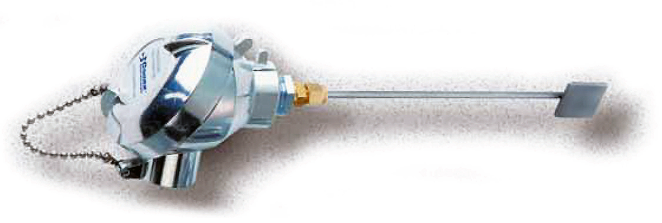
Thermocouples used in process environments at elevated temperatures can change calibration due to contamination of the wires, loss of wire alloying constituents, or as a result of interactions between the components of the assembly (thermoelements, insulator, and sheath material). The degree of drift depends on the process environment and the purity of the materials used to construct the thermocouple. It is not uncommon for the thermocouples to be stable for long periods at 1,000°F in benign conditions. To minimize system inaccuracy, periodically recalibrate the sensor. (Figure 4)
9: Note that Measurement Accuracy is a Function of the Entire System
Often, attempts to achieve a desired measurement accuracy focus predominantly on the temperature sensor itself and do not take into consideration all the elements of the temperature measurement system. These elements may account for a significant portion of the total system accuracy. For example, extension wire tolerances can be as much as two times the limits of error of the actual thermocouple. Reference junctions, whether ice baths or electrical reference junction compensation, can introduce errors of as much as 0.09°F to 1.8°F (0.05°C to 1°C). Readouts of 4 to 20 mA transmitter components are another source of system error. Two-wire, 4 to 20 mA transmitters, for example, may introduce a basic error of 0.9°F (0.5°C). One technique to compensate for this error is to perform a calibration on the sensor/transmitter system. This allows the actual sensor offset to be programmed into the signal conditioner. (Figure 5)
10: Consider Calibration Uncertainty When Evaluating Accuracy
Often, sensors are purchased with calibration data to define the actual offset within the acceptable limits of error. It is important to understand this calibration data reflects an inherent uncertainty. Calibration uncertainty should be at least four to 10 times less than the sensor accuracy you desire. Laboratory-performed calibrations approach uncertainties of ±1.8°F at temperatures of 1,832°F (1,000°C). Typically, this information is supplied on the calibration data certificate supplied with the equipment. After thermocouples have been in use for some time and recalibration is needed, the unit can be calibrated in place or returned for calibration in laboratory conditions. While calibration in laboratory conditions theoretically will provide much less uncertainty, calibration in situ can be useful because it tests the thermocouple in the same conditions and installation configuration in which it is used. In critical temperature measurement applications, knowing the uncertainty of the sensor provides a greater degree of confidence in your own measurements. (Figure 6)


 general practice for CQI-9 and AMS2750E")


