


This paper introduces recent research progress of induction heating technology at Baosteel, specifically the development of full coil static induction heating technology of the backup roller, the development of induction hardening technology of steel pipe, and research on sparking phenomenon during edge induction heating. A computer simulation method has been established and used in these research subjects, which can precisely calculate the whole heating processes and the system parameters. Based on experimental tests and verification, the simulation model has been greatly improved, and the corresponding computed results can be directly used as guidance for the production process, which makes these research works more efficient and accurate.
Introduction
Efficiency, quality, and cost are the three primary concerns of steel companies, while EPM technologies mostly deal with matters related to product quality. Regarding induction heating technology, maintaining the output of a power source in a stable state and obtaining a desired temperature value are the two most important objectives. The heating process and uniformity of temperature distribution are the most prioritized objectives in the application of induction heating technology, which mainly depends on reasonable designing of the induction coil structure and precise controlling of the heating process parameters. With the development of computer simulation technology, the accurate calculation of the induction heating process becomes possible, which makes the application of this technology faster and more efficient. In addition, it is easy not only to obtain the heating temperature but also the induction heating system parameters by computer simulation [1-3].
Recently, the EPM team at the Baosteel Research Institute successfully developed a full coil static induction heating technology for a large forged back-up roller, an inner scanning induction heating technology for large steel pipe, and the edge heating technology for hot rolled steel plate. This paper gives a brief introduction to the development process and main difficulties of the previously mentioned induction heating technologies. Three research topics during the induction heating process — the end-effect and its countermeasures, the precise control of the heating temperature, and the electromagnetic field analysis under complicated working conditions — have been explored and will be discussed.
1. Full coil static induction heating technology of the backup roller
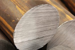
A full coil static induction heating technology was developed for the induction hardening of the backup roller where a solenoid coil with multiple turns covers all the working surface of the heated backup roller during heating [4]. The roller rotates to improve circumferential temperature uniformity, while it is kept relatively static to the induction coil in the axial direction. Compared to conventional heat treatment technologies, the full coil static induction heating technology has an advantage of a much deeper hardened layer and a larger hardness value when used for heat treating of the backup roller. With this technology, wear resistance and service life of the treated roller can be improved to reduce production and maintenance costs. Since a backup roller usually has a diameter larger than 1.5 meters and a height higher than 2 meters, it inevitably takes a much longer heat-treating time than that of conventional induction heating. Moreover, the difference of temperature distribution along the whole roller surface is restricted within ±10°C. These requirements make the industry application of this technology hard to realize, unless we can precisely calculate the induction heating system parameters and control the heating process [5-7].
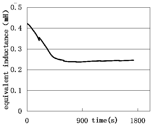
In this study, the backup roller is heated from 450°C to more than 900°C, which has a greater change of physical properties during the heating process and leads to a remarkable fluctuation of the heating system load. This phenomenon makes it difficult to precisely control the heating process. As shown in Figure 1, the equivalent inductance drops with an increase of temperature and then finally reaches a stable value. Furthermore, the initial inductance is almost twice as much as that of the high temperature, which causes the heating frequency to increase almost 50 percent during the entire heating process under the condition that the load capacitance remains constant. This phenomenon not only greatly influences the stable running of the induction heating system, but it also has an important effect on the temperature distribution. Since the thickness of the induction heated layer is required to be more than 100mm, the heating frequency is usually under 100 Hz. On the other hand, the parameters of the induction system change with the size of the backup roller and its corresponding heating coil, which makes designing of the induction system parameters and control of the heating process more complicated.
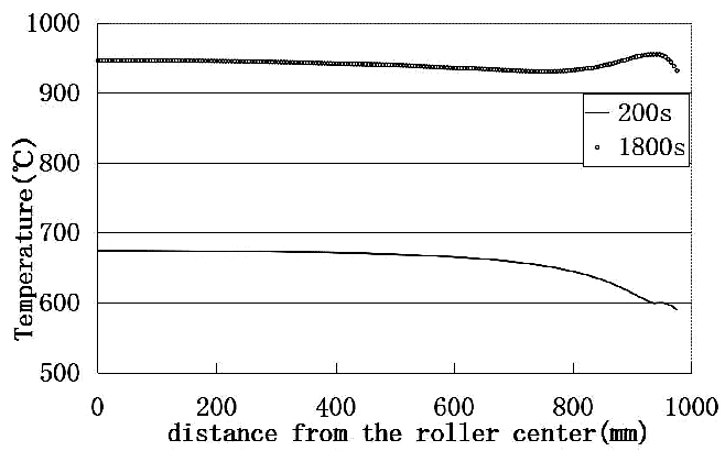
Regarding the temperature distribution, it is relatively easy to obtain a desirable temperature distribution at the radius direction. However, the end effect inevitably occurs when using a solenoid-type induction coil during the heating process, which makes the roller surface temperature difficult to control [8]. As can be seen in Figure 2, the roller surface temperature along the axial direction presents different features of nonlinear distribution over time, which mainly depends on the coil structure, roller height, and coil-to-roller space. When the roll surface temperature is lower than the Curie temperature, the temperature at the end part of the roller is much lower than that of the center part. However, when the roll surface temperature exceeds the Curie temperature during induction heating, the temperature at the end part of the roller will rise rapidly and exceed that of other parts. This means simply changing the induction heating parameters cannot improve the uniformity of the temperature distribution. To solve this problem, an effective way has been proposed and conducted that adjusts the heating-coil currents separately based on the surface temperatures of the corresponding heated roller parts.
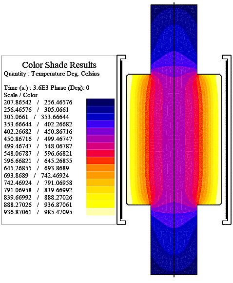
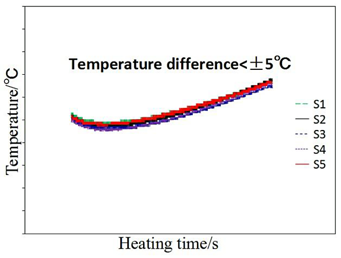
Regarding the hurdles mentioned earlier, a computer simulation used to accurately simulate the induction heating process and temperature distribution. The simulation model was first verified and optimized by experiment results. The final calculated temperature distribution of the roller along the longitudinal direction is shown in Figure 3, where it can be seen that the temperature uniformity of the roller surface layer is well controlled, while the inner part of the roller remains at a relative low temperature. Results of an infrared temperature measurement show the temperature difference of the entire roll surface is less than ±5°C, as shown in Figure 4, where S1∼S5 are the temperature curves measured by an infrared radiation thermometer at different locations of the roller surface during the final stage of the induction heating process. The five curves all but overlap with each other, which means a very uniform temperature distribution has been obtained at the entire roller surface.
2. Induction hardening technology of steel pipe
Wear resistance is one of the key performance indexes of steel pipe when it is used for material transportation, which directly affects its service life and cost performance. In the process of steel pipe production, the use of heat-treatment technology to improve its hardness and wear resistance is an effective method, and has a wide range of applications in industry lines. However, for large diameter steel pipes used for transportation, there are many difficulties in using conventional heat-treatment methods. In this study, a scanning induction hardening technology was applied to the inner surface of the steel pipe, so as to improve its inner hardness and wear resistance. By carrying out a series of research works of composition study, computer simulation, physical experiment, temperature measurement, hardness testing, micro-structure analysis etc., a steel pipe with gradient strength distribution along the wall thickness direction has been obtained.
To improve its service life, the steel pipe is preferred to be induction hardened with more than 50 percent of its wall thickness. Since over-heating will cause grain coarsening, it is important to control the maximum temperature below a certain temperature during the heating process. This peak temperature can be controlled by the heating power, heating frequency, and the moving speed of the steel pipe. In order to precisely control the entire heating process, a computer simulation has been implemented. At a low moving speed, heat conduction becomes dominant, which makes the temperature gradient hard to obtain. As shown in Figure 5, there is a peak value of the inner surface temperature during heating, while the temperature difference along the radius direction soon becomes gentle out of the heating coil, where the temperature difference between the inner and outer surfaces is only within 20 degrees at the starting quenching position. Therefore, in order to increase the temperature gradient, the moving speed of the steel pipe should be increased.

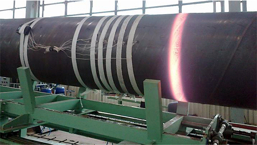
An induction hardening experiment was implemented to study the real heating process and the mechanical properties of the treated steel pipe. The temperatures measured by thermocouples at different locations of the steel pipe during the induction hardening process are well in accordance with the calculated results. In Figure 6, a high temperature ring with uniform temperature distribution in the circumferential direction of the steel pipe can be seen during the experiment. This ring moves with constant speed and with a stable temperature distribution during the entire induction hardening process, which guarantees a 1,400 MPa strength of 10mm thickness of the steel pipe under a suitable steel composition.
3. Research on sparking phenomenon during edge induction heating
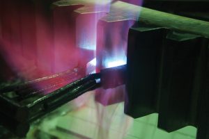
An edge heater having a “C” shape connecting core is used for induction heating of hot rolled steel plate. During the application of an edge heater, a spark phenomenon often occurs, which is induced by discharge arcing between the conveyor roller and the heated steel plate. In order to avoid this, some preventive measures can be implemented, such as keeping conveyor rollers insulated to the ground, manufacturing the roller with unequal diameter, inputting the nearby coil currents with opposite direction, and so on. Because of the bad conditions at the production line, iron scurf and water mist can destroy the insulation grade of the roller. It is difficult to keep the high value of insulation for a long period of time, which brings a greater challenge to stable production and maintenance.
Analysis shows the main factors that cause the spark phenomenon include: (1) surface roughness of the roller, (2) the insulation value of the conveyor rollers, and (3) magnitude of the induced eddy current in the contact positions between the conveyor roller and steel plate. The surface roughness and the insulation value of the roller basically depend on field maintenance of the conveyer rollers, while the induced eddy current is influenced by many factors, such as the deviation of the steel plate during moving, the width of the steel plate, the relative position of the coil, the heating power, and so on. It is obvious that, if the induced eddy current at the positions of the conveyor roller in contact with steel plate is small, sparking between the steel plate and the roller is less likely to occur. In this study, the previously mentioned factors that affect induced eddy current are analyzed by numerical simulation. The numerical simulation model was verified and optimized by experiment results to improve its accuracy.
It was found there is a significant difference for different steel plate width in their current density distribution along the roller-to-plate contact line. The maximum eddy current density at the contact line of a narrow steel plate is bigger than that of a wide steel plate. This result reveals it is more likely to cause a spark when heating a narrow steel plate.
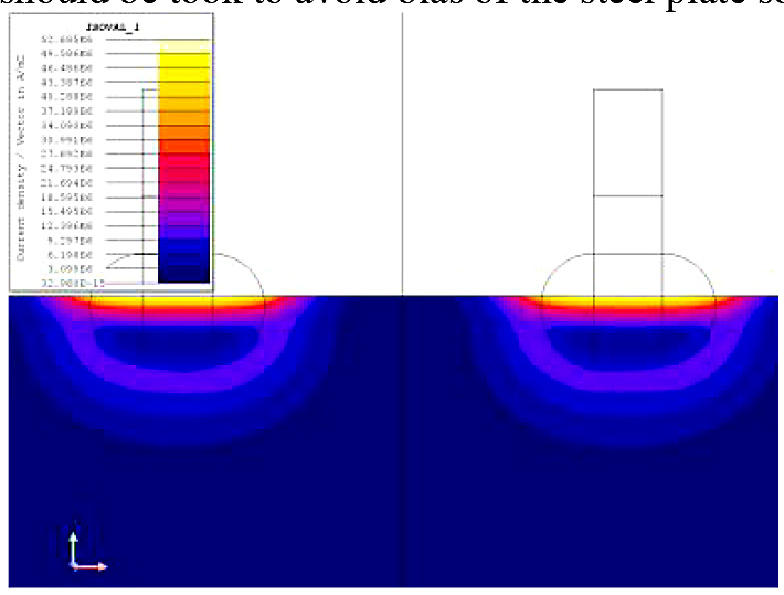
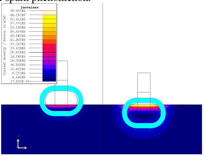
On the other hand, there are usually four coils connected in parallel on both sides of the steel plates. During the heating process, steel plates are easily shifted to one side, which cause a load-match unbalance for the induction heating power system (Figures 7 and 8). It was found that, under the same input current, the induced current on the more coil-covered side of the steel plate is larger than that on the other side. This result indicates the probability of a spark and is greatly increased when the steel plate deviates to one side of the induction coils. Moreover, the previously mentioned load-match unbalance further strengthens the uneven distribution of the input current in the coil, resulting in a great bias on the induced current in the steel plate. Thus, the steel plate will be heated to different temperatures at each side of the steel plate, resulting in uneven physical properties along the steel-plate width. Therefore, it is strongly recommended that effective measures should be taken to avoid a bias of the steel plate so as to decrease the spark phenomenon.
Conclusions
This paper mainly focuses on recent research about applications of induction heating technology in Baosteel, where three research topics related to roller, plate, and pipe have been studied. Although shapes of the treated work pieces are very simple in these cases, special requirements make the industry application of induction heating technically difficult. Through the previously mentioned research, the following conclusions can be obtained:
Computer simulation is an indispensable way to apply modern induction heating technology, which can accurately guide the industry process.
Sufficient attention should be paid to non-electrical factors that greatly affect the induction heating process, such as moving speed, surrounding condition, and so on.
References
- Yu. A. Samoilovich, Steel in Translation, 45(2015), 73-79.
- S.Nobuo,M.Shinji,E.Shigeru, JFE technical report, 2008, 11, 1-6.
- M.Behulova,B.Masek,L.W. Meyer, Materialpruefung, 2006, 48, 217-224.
- Union Electric Steel, Forged Roll Heat Treatment[OL], http://www.uniones.com/the-ues-difference/forged-roll- technology/forged-roll-heat-treatment.
- L.Zhigang,J.Haichao,Z;Feng,et al., Heat Treatment of Metals, 36(2011): 115-118.
- C.Tianxiang,W.Zhanjun, Heat Treatment of Metals ,41(2016), 149-153.
- W.Cunyou,J.Xiaoli,Z.Yueming,Heat Treatment of Metals, 43(2018), 216-221.
- R.E. Haimbaugh,Practical induction heat treating[M],ASM international,2001, 50-51.
This article was published under license by IOP Publishing Ltd. IOP Conference Series: Materials Science and Engineering, Volume 424, conference 1. This is an open-access article under the CC BY license (creativecommons.org/licenses/by/4.0/). The article was edited to conform to the style of Thermal Processing magazine. The original article is available at: iopscience.iop.org/article/10.1088/1757-899X/424/1/012061/meta


 general practice for CQI-9 and AMS2750E")


