


I teach pyrometry courses throughout the year and, when I do, I include a thermocouple tutorial video from YouTube. In this video the function of thermocouples is discussed, and examples shown. I have always thought that this video gave good examples, although a friend of mine who was attending one of my courses was nice enough to tell me that he felt the video was, well, let’s just say “corny” for lack of a better term. He and I then discussed different ways I could present the technical workings of thermocouples. As he said, “thermocouples are simple; dissimilar wire emits an EMF signal, which is then turned to temperature.” While he is generally correct, there are details in between that thermocouple users may find valuable or, at the very least, interesting.
Thermocouple type and usage tends to receive quite a bit of attention. In this article, we will examine the history, basic function, and requirements of thermocouples used in thermal processing.
History
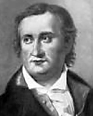
Typical historic accounts of thermocouple technology begin with Thomas Johann Seebeck’s accidental discovery of the thermocouple in 1821. There is a back story that helps support Seebeck’s involvement and eventual, albeit accidental, discovery.
Seebeck, born in Estonia April 9, 1770, was the son of a wealthy merchant who left home at 17 to study medicine in Berlin. Seebeck was financially independent due to his father’s wealth and had an attraction to natural science. Because of this, he eventually changed his focus to private research, where he worked on optics.
Arriving in Nuremberg in 1810, he met and was the guest of Hans Christian Ørsted, who was a physicist and is responsible for discovering the connection between electricity and magnetism (Oersted’s law). This connection once again changed Seebeck’s focus from optics to electromagnetism. It was 1821 when Seebeck announced his discovery of the thermocouple. Once announced, Seebeck’s experiments were repeated throughout Europe in several areas of research, cementing thermocouple technology.
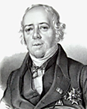
While Seebeck is credited with the discovery, thermocouple technology as it exists today owes homage to several other scientists. Professor P.G. Tait of Edinburgh University performed several tests in an attempt to establish thermo-electric diagrams. He concluded thermocouple technology is based on electromotive force (EMF), which is a parabolic function of an absolute temperature. Tait also stated that the slightest impurities in the metals will severely change the accuracy of the readings.
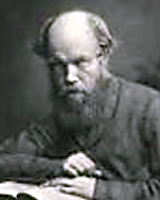
Of course, there were American contributions as well. Dr. Carl Barus was researching high-temperature measurement and attempted his study with multiple alloys of platinum-iridium.
The first available temperature measurement device shows up in a Cambridge Instrument Company catalogue from 1898, although it was not available until 1902 once a large enough collection of platinum and rhodium-platinum was obtained from Johnson Matthey.
There are several other scientists not mentioned who also had an influence on current thermocouple technology.
Thermocouple Technology
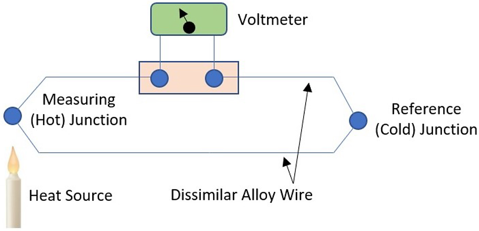
Let’s start with the definition of a thermocouple. According to the ASM Materials Engineering Dictionary, a thermocouple is “a device for measuring temperatures, consisting of lengths of two dissimilar metals or alloys that are electrically joined at one end and connected to a voltage measuring instrument at the other end. When one junction is hotter than the other, a thermal electromotive force is produced that is roughly proportional to the difference in temperature between the hot and cold junctions.” [1]
While this definition is much more detailed than that of other publications, it underlines the basic principles of a thermocouple.
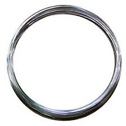
Each thermocouple has two dissimilar wires that produce a voltage in the microvolt range (Figure 1). Due to being a microvolt, the wire must produce enough voltage to produce an accurate reading. Each one of the wires, being different alloys, has an electric potential gradient in line with the temperature gradient of each wire. The thermoelectric EMF is different in specific alloys for the same temperature, and it is this difference that allows thermocouples to be used to measure metal temperature.
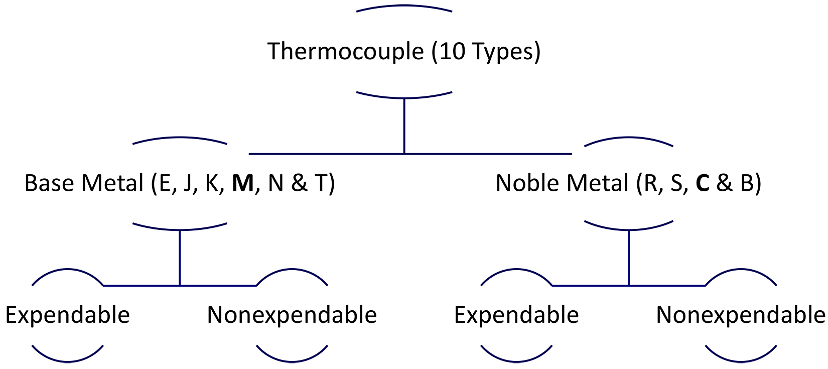
Each wire that makes up the thermocouple is a different metal/alloy. As an example, a type K thermocouple is an alloy called chromel (90% Ni and 10%Cr) on the positive leg and an alloy called alumel (95% Ni, 2%Mn, and 2%Al) on the negative leg. For type K thermocouples, the negative leg is magnetic, making it a bit easier to assemble thermocouples to the appropriate plugs before use. Thermocouples are then separated into base metal and noble metal. Noble metal thermocouples are those containing precious or noble metals, such as Type R and S. It is then that thermocouples can be separated into the expendable or nonexpendable categories (Figure 2). What governs the appropriate category is the type of insulation the thermocouple is purchased with. Put simply, expendable thermocouples can generally be those covered in fabric or plastic-covered wire, and nonexpendable thermocouples are all others. Thermocouple usage limitations are typically defined by expendable and nonexpendable categories, although industry specifications differ, and each user should be aware of the applicable specification limitations.
Thermocouple Limitations
Thermocouple temperature limitations are governed by the type (alloy combination) of the thermocouple. In keeping with our example, type K has a range of minus-328°F to 2,282°F, although most users do not use type K thermocouples below ambient, as other thermocouple types (i.e. type T) are better suited for negative/lower temperatures due to their accuracy.
Each thermocouple type has its advantages and disadvantages. Type K is suitable for oxidizing atmospheres in higher temperature ranges, provides a more mechanically and thermally rugged unit than platinum, rhodium-platinum, and longer life than iron. A disadvantage of type K is it is especially vulnerable in reducing atmospheres, requiring substantial protection when used in such atmospheres.
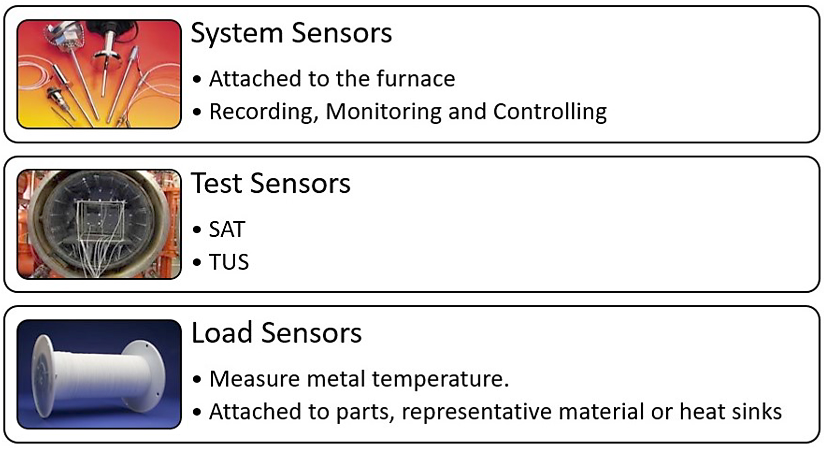
Typical use of thermocouples within thermal processing will align with three categories: system sensors, test sensors, and load sensors (Figure 3). Again, each prime/industry specification may have its own nomenclature for these categories, but in general, these are the three categories of use. Within thermal processing equipment, these categories of thermocouples may be different types depending on the instrumentation type configuration. As an example, a vacuum furnace may have a type S control and overtemperature thermocouple, while the load and test thermocouples are type K.
Thermocouple suppliers can typically help users identify what type of thermocouple will be best to use on their specific process and will be based on temperature and heating environment, as well as heat cycles.
Summary
Understanding thermocouple technology is essential to proper thermocouple use. Consideration of the environment, temperature, and temperature cycling, as well as physical damage, should be considered when using or purchasing thermocouples.
References
- Thermocouple definitions – AMS2750G, Table 2 & ASM Materials Engineering Dictionary. – 1992, pg 479.
Sources
- “The Early History of the Thermocouple,” L.B. Hunts, M.Se., Ph.D.
- Dataforth Corporation AN106 — www.dataforth.com


 general practice for CQI-9 and AMS2750E")


