


When providing heat treatment for aerospace gears and bearing components, manufacturers are traditionally left with three choices for thermal processing: continuous flow atmospheric furnaces with press quenching in oil, or batch heat treatment in both vacuum and atmospheric furnaces with quenching in oil (or high-pressure gas, as in vacuum). All three techniques differ in benefits and disadvantages associated with geometric distortion, environmental impact, and safety concerns.
A single-piece flow (SPF) vacuum heat-treatment furnace with the capability to provide high-pressure contour gas quenching to a single piece or “4D Quench” (4DQ) provides continuous flow heat treatment with low geometric distortion, environmental impact, and personal safety concerns. This system has the flexibility of operating in a batch style work cell, or it can be sized up and inserted in a continuous work cell, operating without human interference. 4DQ technology equals the speed of an oil quench and the cooling gas nozzle profile can be optimized based on actual part geometry. By controlling the direction of the cooling gas spray with part rotation, manufacturers now have the ability to control how fast or slow a part section cools providing a better quench. With this improved uniformity, larger and previously pressed quenched parts can now be processed in a 4DQ system.
SPF vacuum heat treating system will thermally process and quench every part the same way, in the same position, with the same timing, one by one. All components undergo the same process parameters, producing consistent and high-quality results for an entire part series. With SPF vacuum heat treatment, aerospace gear and bearing manufacturers can safely and environmentally friendly output identically processed and uniform components while reducing geometric distortion of their heat-treated components. This article will also summarize a half decade’s worth of research associated to SPF with 4DQ Vacuum Heat Treatment.
1 Introduction
Aerospace work … what can you say … well, you can say a great deal about the topic. Manufacturers who meet the rigorous standards set forth by the aerospace industry will say, “It is challenging.” The demands of aerospace applications stretch the boundaries of material science daily, while they seek to maximize efficiency at the lowest possible weight. These rigorous standards also come at a high cost and lead manufacturers to seek cost saving opportunities in any area of the manufacturing process.
Aerospace vehicles are designed to oppose one of nature’s most relentless forces: gravity. As such, the vehicles are designed and manufactured to overcome these forces to promote transport of humans and/or materials to both the accessible and not-so-accessible parts of the globe at a moment’s notice. This means aerospace components have a common interest: Lighter is always better. But how do you get there? It’s a constant struggle between a component being lightweight yet having good strength and mechanical properties. In addition, these components must maintain this strength in some of the harshest working environments on Earth.
Materials are constantly being developed to meet these rigorous requirements through improved strength at reduced weights. Yet, with all the material advancements, the capabilities of the heat-treating industry have remained nearly stagnant.
Why, you ask? There are many reasons, but one specifically pertains to the fact that historically, materials have been designed around “standard” heat-treatment techniques. This is counterintuitive. If you look at the entire manufacturing chain, there are countless efforts to improve quality, manufacturing time and mechanical properties. These improvements are achieved by manufacturers investing time and resources to incrementally (and sometimes drastically) improve various links in the chain. However, heat treatment now has finally made the turn and is catching up to other manufacturing advancements. This heat-treatment advancement has come from an unlikely, or should I say unexpected, source: the quenching chamber.


2 Helicopter Production
Looking at helicopters, for example, a private helicopter cost can fall in the range of $250,000 to $2 million for a new unit. Contrast this with military applications where a new unit can cost up to $72 million.
Advancements have been made throughout these aircraft on a nearly continuous basis thanks to customer demands for higher, and in some cases, extreme performance. By default, these advances in components have resulted in advancements in the manufacturing process. This is true for one of the key systems needed to meet the extreme performance demands: the aircraft transmission systems. Here, advances in materials and machining are common, but heat treating remains stagnant. Manufacturers that produce transmission and bearing systems are under the highest levels of scrutiny to produce ultra-high-quality components to the tightest of tolerances with sophisticated machining centers and quality measurement systems. To do so, transmission system components are heavily reliant on heat treatment and its ability to ensure the components will survive the very demanding working conditions set forth. If the heat treatment fails while an aircraft is in operation, there can be catastrophic consequences. To ensure the aircraft will perform as intended, there is a large portion of the manufacturing process dedicated to the transmission system accounting for 9 percent of the overall cost to manufacture a helicopter [4] and in some cases can be as high as 15 percent. If you take the 15 percent cost of a transmission system against the overall cost of $72.1 million for the V-22 Osprey, this can amount to $10.8 million.
Transmission systems use (but are not limited to) hardening/case hardening materials such as 8620, 9310, Pyrowear X53, Ferrium C62, Ferrium C64, M50, 440C, 52100, BG-42, Pyrowear 675, etc. As such, these materials will all respond differently when subjected to thermal processing and quenching. With varying production methods, manufacturers must take special care when producing a gear/bearing as distortions attributed to the heat treatment are very expensive to correct/rework and even more expensive to start over if materials deviate too far out of specification. As a result, established thermal processes in this field are slow to evolve.
3 Batch Oil, Batch HPGQ & Press/Die Quenching
When working with the various grades of materials, not only do machining practices require adjustment, heat treatment must be adjusted as well. A one-size-fits-all solution (as is in traditional heat treatment) is not the most effective or optimized way to thermally process materials. Batch processing leads to a high variation from part-to-part including but not limited to different thermal exposure, carbon absorption, heat transfer coefficient during quenching, and geometric distortions after the completed process.
Analyzing geometric distortions closer, batch processing (specifically when oil is the quenching media) provides the most inconsistent quenching platform among the common methods used. Batch processing in high pressure gas quench (HPGQ) systems will provide less distortion than that of oil as it is a much softer (less aggressive) quench. A tradeoff with HPGQ vs. oil quenching is that HPGQ in traditional vacuum heat-treatment systems does not have the same heat-transfer coefficient capability than that of oil. As a result, HPGQ has a more difficult time to quench lower alloy and thick cross section gears/bearings to achieve the desired mechanical properties.
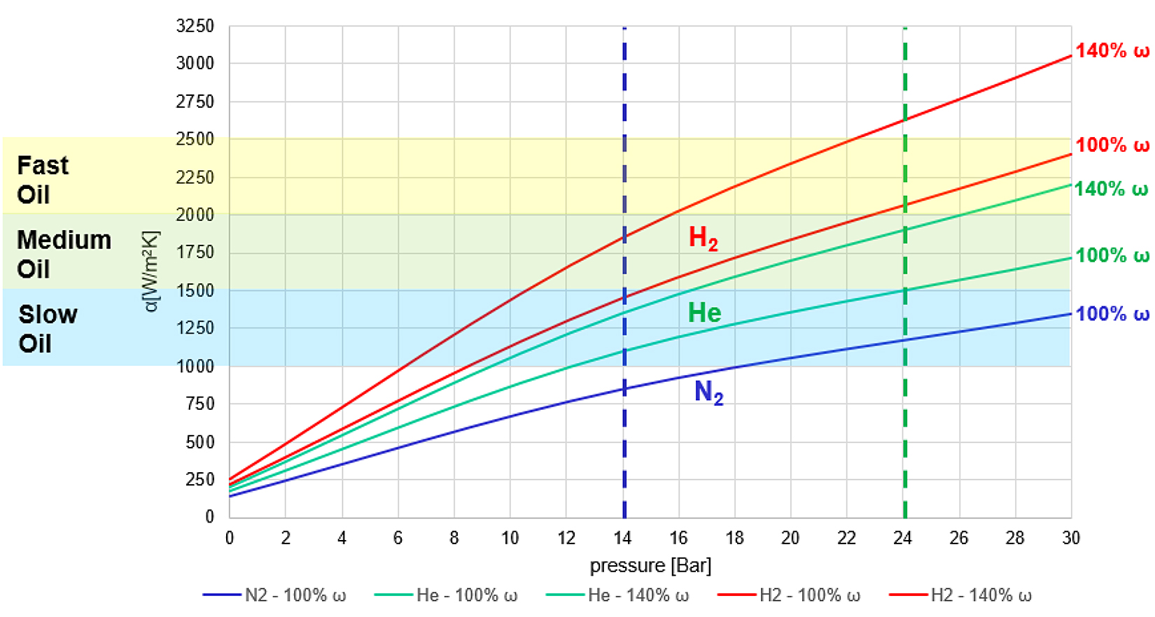
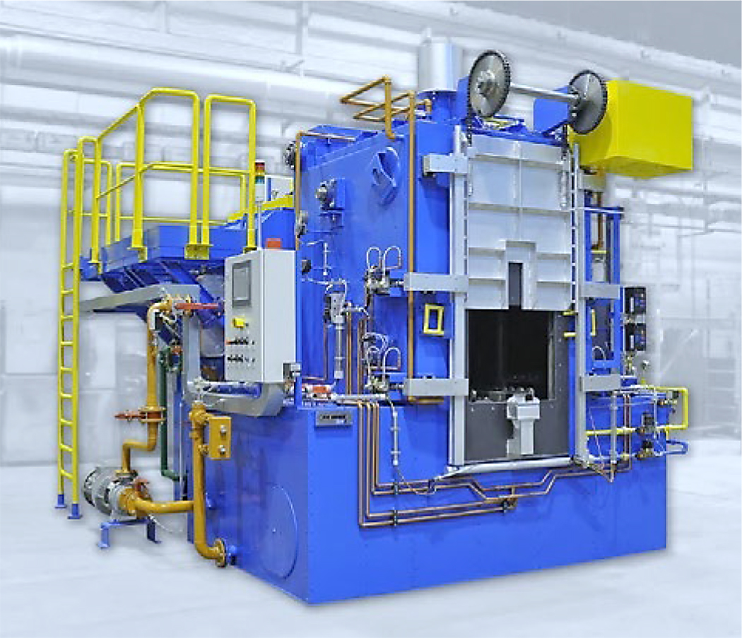
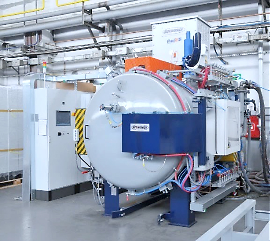
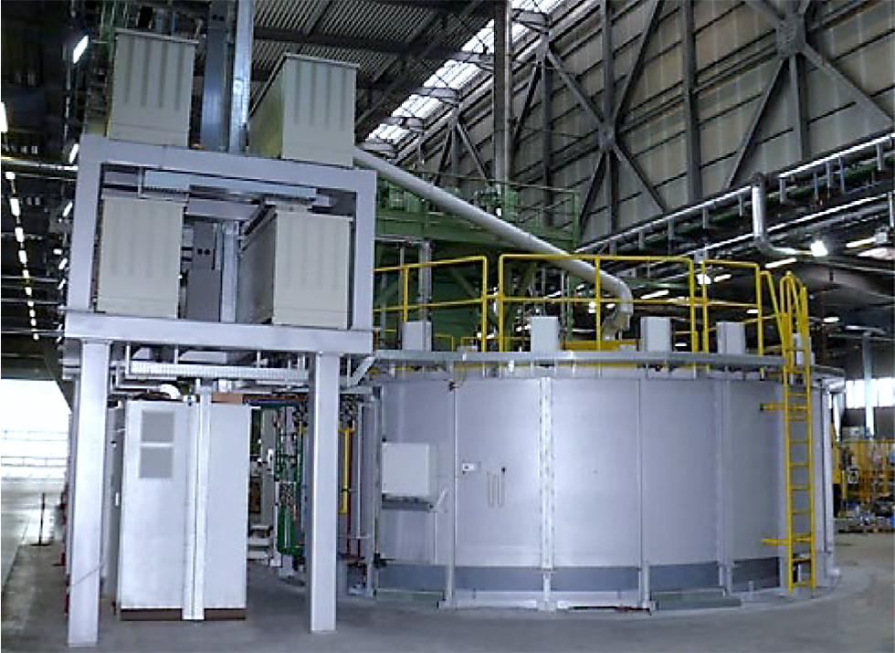
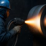
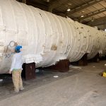
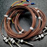
Figure 1 shows heat-transfer coefficient α[W/m2K] when quenching in a batch furnace with high pressure gas quenching versus slow, medium, and fast oils. With nitrogen gas (most commonly used high pressure gas quench in the market), you will need a 16 Bar gauge to begin to quench as fast as a slow oil. Helium and hydrogen can be used; however, helium is very expensive, and helium-recovery systems are as expensive as the furnace itself. Hydrogen is abundant and very inexpensive; however, with safety concerns in mind, it is not a practiced quenching method. Referencing the ω lines, this represents the cooling power capacity when applying higher power loads to the cooling fans during the beginning of the quench cycle. Figures 2 through 5 represent traditional heat-treatment equipment for processing aerospace gear/bearing components.

When HPGQ is not strong enough and batch oil quench provides too much distortion, this can force a gear/bearing manufacturer to resort to the press/die quenching technique after thermal processing of the material. Press quenching is an effective technique to achieve proper hardness while reducing geometric distortion. The press quenching process is well suited for:
- Case and through hardening of steel parts (gears, rings, etc.).
- Parts sensitive on hardening distortion.
- Thin cross section and large dimension parts.
- Individual hardening.
- Maintaining dimensional stability which controls distortion.
- Good repeatability of the results.
- Distortion related to press quench hardening can keep the quality features from changing only 1 to 2 AGMA Class differences from a green gear condition.
With all the benefits associated with press quenching, there are tradeoffs to this approach as well. When considering the press quench method, disadvantages to be considered with the heat-up furnace include:
- Gear quality issues associated with intergranular oxidation (IGO).
- Equipment safety issues with open fires and radiation.
- Equipment environmental issues with carbon monoxide and carbon dioxide.
- After heating the furnace, one must consider the process of transferring an individual gear/bearing from the furnace to the press quench equipment where:
There are operator safety issues as they can be exposed to high levels of thermal radiation from the furnace and when manually handling the gear while it is at temperature.
Additional quality issues are associated with IGO during transfer from furnace to the press quench.
Concerns with the oil press itself include:
- Safety issues related with the open fire.
- Health and environmental issues associated with oil vapor emissions.
- High costs associated with expensive quenching dies needed for each part geometry.
- After press quenching, the need for a parts washer is required for oil removal prior to tempering and post machining:
- The washing process requires special chemicals and upkeep for system operation.
- Environmental issues associated with the neutralization of the washed oils.
4 Aerospace’s Transmission Problem: Distortion
Traditionally, when heat-treating distortion is a problem (no matter the heating or quenching method) but the mechanical properties are as desired and the component works in its application, there is a solution: Make more parts. To increase the volume of parts produced (over the required quantity), the attrition from heat treatment is accounted for. A newly released design can have above 70 percent in attrition where a mature design can have up to 25 percent. Materials distort for many reasons, raw material composition, Jominy of the steel (hardenability), aggressive machining, heating ramp, carburizing, quenching, etc. Engineering and production can then be led to choose the press/die quench method, which promotes less distortion, or it can be used to remove distortion already existent in the part before quenching.
An additional point to consider: Aerospace parts are not like automotive where aerospace runs are in small batches (say 20 to 40 pcs) from a wide variety of geometry and sizes. This fact alone has made it difficult to plan for the heat-treatment demands required for aerospace gears/bearings. In special cases, some of the most difficult aerospace gears can cost more than $50,000 per gear to produce. Because of this, maximum care must be taken at all areas of the manufacturing process to ensure the gear does not deviate from specification during production.
5 Aerospace’s Transmission Solution: 4D Quench
4DQ is a new technique that has six years of maturity and is the first heat-treatment advancement of this kind. 4DQ is a tool that can provide gear and bearing manufacturers significant improvements to the quench process as it gives full control of how fast or slow heat is removed from a component’s geometric area. Quenching can now be engineered and planned vs. guessing based on years of experience. Heat transfer coefficients at specific sections of a component can be controlled, for example, in the case of a heavier cross section, one may want a much faster heat transfer; however, in a thin cross section, a much lower heat transfer may be desired (if any at all). This type of control allows for homogeneous cooling of the entire component throughout the 4DQ process.
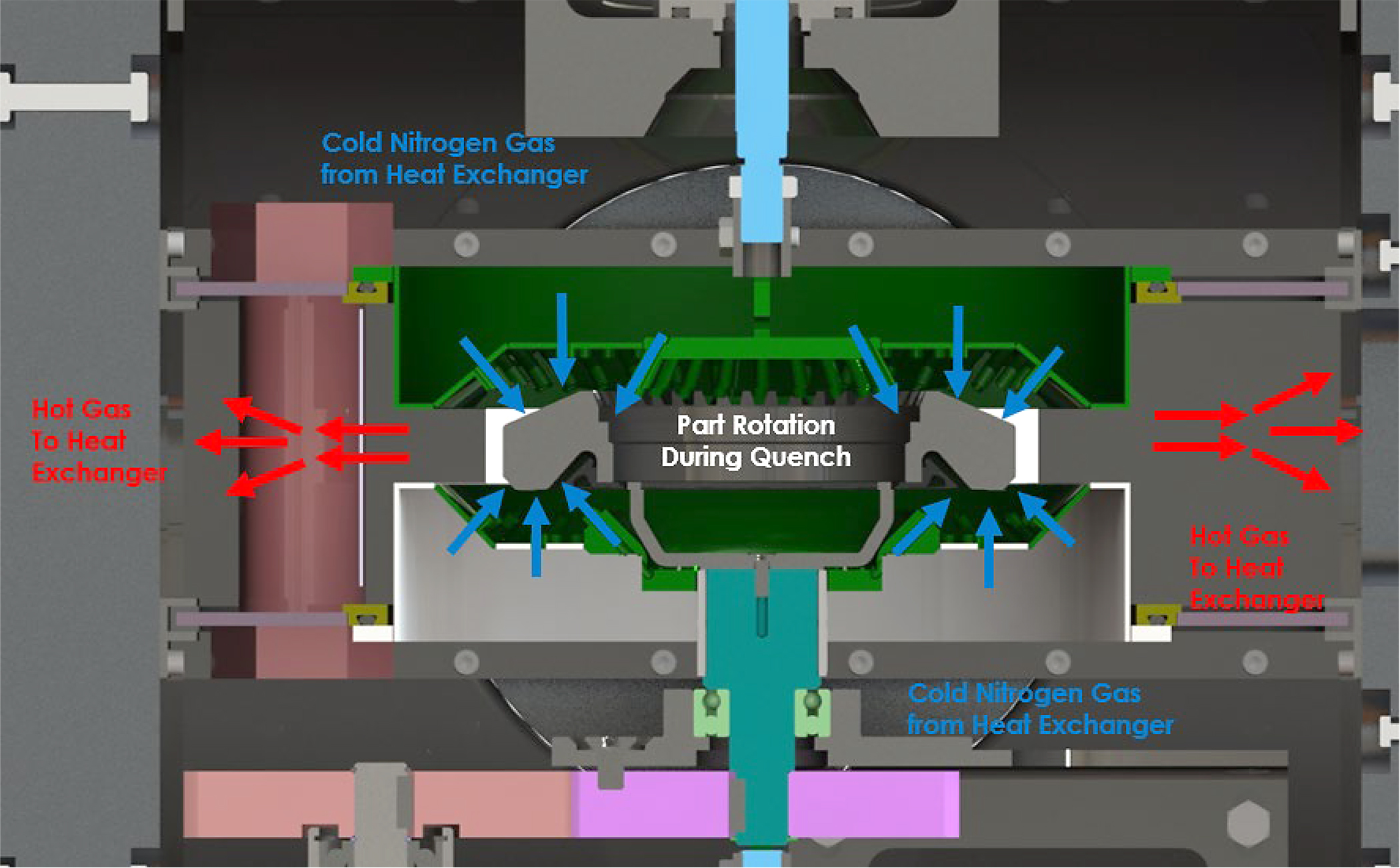
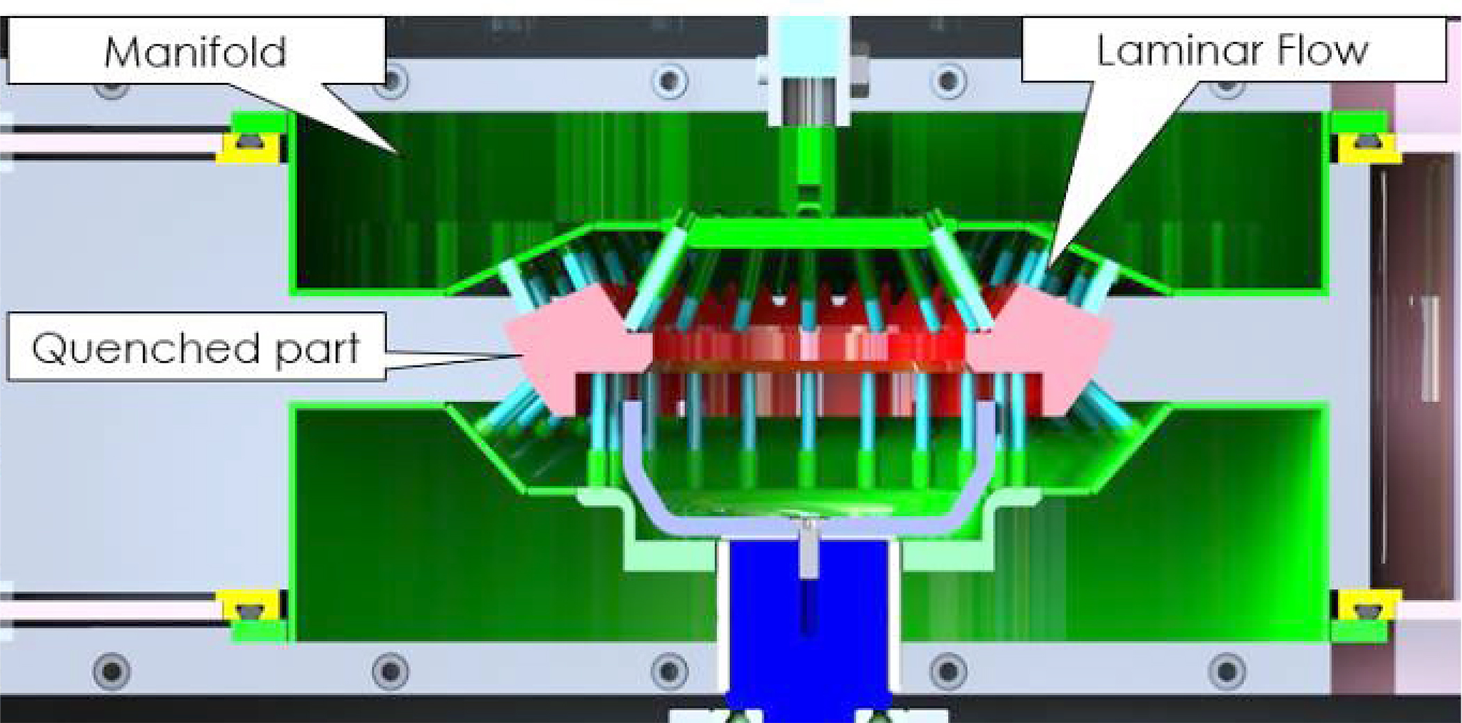

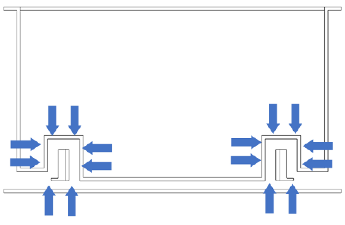
4DQ works when a component is placed in the quenching chamber; the chamber is then pressurized (up to 10 Bar abs.); the powerful cooling blower(s) are engaged and starts the closed loop circulation of the pressurized gas. The cold quenching gas passes through the quenching manifold nozzles or orifices and passes across the desired section of the gear/bearing with the hot gas exiting out the side between the top and bottom manifolds and on its way to the heat exchanger to then return back to the manifold. This process only describes the system’s 3D quenching capabilities, to introduce 4DQ, the gear/bearing is then rotated as the cooling gas passes over the component creating a contoured cooling profile around all desired surfaces. Combining the 3D gas flow from the nozzle manifold and the 1D of part rotation, you now have a true 4D quenched component.
6 4D Quench: Large Component Capacity
Unlike automotive components where there are vast quantities of the same gear manufactured, aerospace has a very different demand in the form of smaller numbers of complicated gear shapes. Thus, they require different thinking on how the manufacturing process will work. With the wide variety of component geometries, alloying elements, demand for reduced weight and low-production volumes to the aerospace industry, these constraints lead to the need for heat-treatment equipment to be flexible as to accommodate the wide array of geometries with small lot sizes. When gear and bearing manufacturers have gears/bearings to produce that have diameters of 12”, 18”, 24”, 36”, etc., 4DQ has the answer. 4DQ systems are modular in design and are flexible to meet any gear/bearing size demand. A single-piece flow SPF vacuum furnace with low pressure carburizing (LPC) and a 4DQ system can accommodate the largest of diameter gears/bearings that the aerospace industry is required to produce. Able to process materials all under vacuum, this system has separate chambers for material handling, heating/carburizing, and 4DQ. Materials and fixtures of varying sizes can pass through this furnace allowing manufacturers not to have to worry about the wide variety geometric configurations and batch sizes they are required to produce. This type of furnace can also be placed in line with a machining work center where gears/bearings can be green machined, washed, pre-heat-treatment inspected, heat treated in the SPF furnace with 4DQ, and onto post processing.
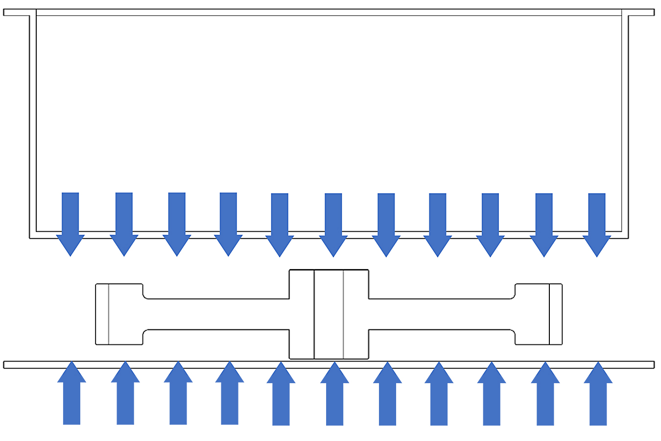
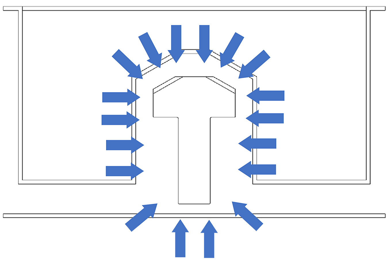

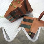
Figures 9 through 11 show examples of various 4DQ manifolds for different geometric profiles. Figure 8 represents a standard vertical flow manifold as the nozzles/orifices are evenly distributed on both the top and bottom manifolds providing vertical quench flow. Figure 9 represents a pinion type manifold where the top manifold surrounds the length of the pinion and contains the majority of nozzles with a close concentration of nozzles where the pinion head is oriented. Figure 10 is for a larger ring type gear where the nozzles are concentrated around the entire contour of the ring gear. Figure 11 is an example of a 4DQ generic manifold that provides even and horizontal gas flow around the component and can be used with any geometric profile that fits within the furnace working volume. There can be multiple columns surrounding the working diameter.
7 4D Quench: Modularity
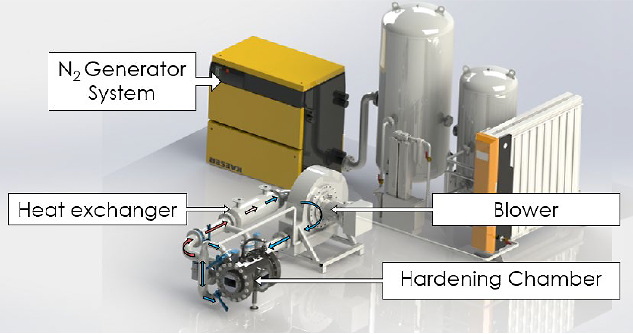
4DQ is not only designed to be adjacent to the SPF furnace; however, because it is a modular system, it can be paired with other furnace processing systems. The system in Figure 12 isolates the 4DQ system showing its main features such as the hardening chamber, heat exchanger, and blower. A nitrogen generator is presented in this example; however, nitrogen can be supplied by a bulk nitrogen system. When oxidation is not a concern, 4DQ can also operate with clean compressed air, allowing it to be a companion quenching system to an atmospheric heat-treatment system. What this means is that 4DQ not only can operate with vacuum equipment, but it can operate with atmospheric systems as well, giving manufacturers a new vision of how to better process their materials.
8 Dimensional Stability
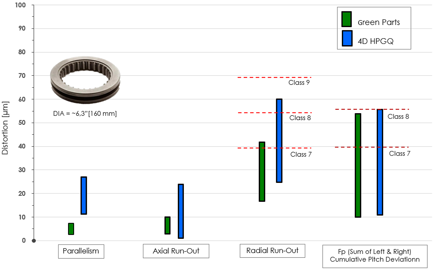
In Figure 13, the 4D HPGQ process was completed on a coupling gear with internal teeth. Measurements were analyzed in a pre-heat-treatment condition and post hardening condition. The coupling gear was produced from 8620 and had a 6.3” [160 mm] outside diameter.
9 Summary of 4DQ Benefits
- Reduction, prediction, and control of distortion.
- Precision and repeatability of results.
- Improved safety and no fire risk.
- Total process automation and integration.
- Full single part traceability and reporting.
- Flexible, on-demand operation.
- No human involvement and impact.
- Compact footprint.
- Elimination of press tooling.
- Eliminates the need for furnace fixtures.
- No decarburization or oxidation.
- Clean part surface (vacuum).
- Nitrogen or Air quench (neither oil nor helium is needed).
- Elimination of copper masking or stop off paints.
- Elimination of high-temperature radiation.
- Elimination of oil and oil vapor contamination.
- Elimination of washers and cleaning chemicals.
- Safe and environmentally friendly process.
10 Conclusion
Heat-treatment distortion is a problem for aerospace gear and bearing manufacturers. Attrition due to heat treatment is a constant struggle that unfortunately has been a problem for far too long. Engineers are great at solving problems when given the proper devices to do so and machinists can do highly precise work with steel when they have proper amounts of steel to machine away. When material-size change during the manufacturing process is unpredictable, engineers and machinists become very ineffective at what they are good at. 4DQ can be viewed as a new tool that manufacturers can now pull from their toolbox to have an answer for controlling distortion during heat treatment. 4DQ is flexible, modular, and can be used in many heat-treatment applications. It is environmentally friendly and is a low-cost solution for extremely high- quality output. 4DQ provides controlled cooling, giving predictable results with minimal distortion ,which leads to a reduction to the amount of work in process, attrition, and increase of overall quality of the materials and downstream operations.
Acknowledgments
Research and publications were supported by the National Centre for Research and Development as part of project no. POIR.04.01.04-00-0087/15 entitled: “Equipment for high performance and precise heat treatment with a quenching deformation reduction system for direct application in downstream production chains of mechanical gearing and bearings.”
Bibliography
- TOSUM, “How Much Does a Helicopter Cost?,” https://toughnickel.com/misc/How-much-does-a- Helicopter-cost.
- Boeing CH-47F Chinook, https://aerocorner.com/aircraft/boeing-ch-47f-chinook/.
- Sikorsky S-70i Black Hawk, https://aerocorner.com/aircraft/sikorsky-s-70i-black-hawk/.
- Bell Boeing V-22 Osprey, https://aerocorner.com/aircraft/bell-boeing-v-22-osprey/.
- Reddick Jr., H.K., 1975, “Army Helicopter Cost Drivers”, Army Air Mobility Research and Development Laboratory Fort Eustis, Virginia, pg. 12, https://apps.dtic.mil/sti/pdfs/ADA015517.pdf.


 general practice for CQI-9 and AMS2750E")
")


