


Composite cure ovens are becoming larger than ever to accommodate enormous composite parts that require vacuum bag curing and post cure.
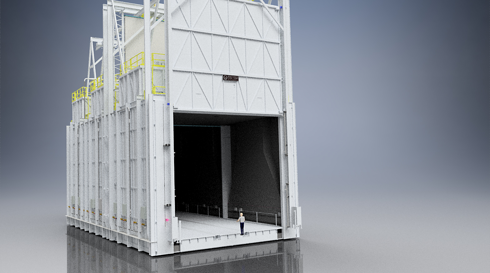
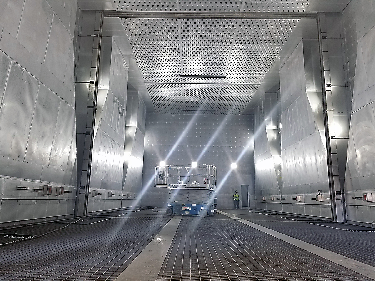
When a leading private space exploration company decided to manufacture its rocket fairings out of composite material, instead of the aluminum alloys used in the past, it would be breaking new ground. These would be the largest composite fairings ever made. Composite materials must be cured in a high-performance oven capable of heating and cooling at a strictly controlled rate and maintaining very tight temperature uniformity throughout the heating chamber.
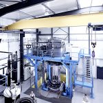
In order to cure these fairings, the company purchased the largest composite cure oven ever manufactured. The oven had a heating chamber that was 34 feet wide x 90 feet long x 32 feet high and a load capacity of more than 100,000 pounds with a maximum temperature rating of 500°F. In order to ensure the temperature inside the oven was within tolerance, the oven had to pass a uniformity test using test thermocouples to measure the air temperature at 210 locations within the heating chamber. After the equipment was installed and final adjustments were made, the thermocouples all measured within ±10°F of the oven set point at three different temperatures. To achieve this feat, the oven featured a 272,000 CFM (cubic feet per minute) blower system, which recirculated 1.2 million pounds of air per hour across the parts. (Figures 1 and 2)
The oven also had an extensive vacuum system required for vacuum bagging the parts. It used 100 individual vacuum ports, each capable of operating at a different separate vacuum level and maintaining each of them using closed loop control.
The oven airflow system was designed using computational fluid dynamics (CFD) software, which simulated the air circulating throughout the heating chamber and around the parts in three-dimensional space. Through this airflow modeling, it was determined the best airflow pattern was bottom-up, in lieu of the more conventional combination airflow using supply ducts on the side walls of the heating chamber. In order to provide the bottom-up airflow pattern, a large supply duct was buried in the floor under the load and had air supply louvers on the top to direct air vertically upward and through the heating chamber. The duct was the same width and length as the heating chamber. This thoroughly bathed the load in heated air, and left no areas where it could bypass around the parts.
Aerospace ovens become more intelligent with Industrial IoT
Over time, all industrial equipment will experience wear and become vulnerable to breakdown, and this includes industrial ovens. In the aerospace industry, a single load being processed in an oven can have a value of well over $100,000. It is critical, therefore, that unexpected shutdowns be minimized to avoid the loss of a load. The latest technology to ensure maximum oven uptime and avoid shutdowns is an industrial IoT (Internet of Things) performance monitoring system.
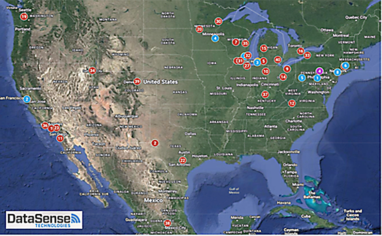
The IoT system tracks the performance and health of a variety of oven components and operating conditions such as motor vibration, controller output percentage, chamber pressure, motor speed, current draw, burner operation, and many others. The system features an IoT gateway, which collects information from predictive maintenance sensors that gather performance data from the oven. The gateway wirelessly transmits the data to a cloud platform where it is displayed in dashboards designed for viewing and analytical monitoring. Thresholds can be set around warning or alarm conditions, and when exceeded, the system alerts the oven manufacturer or the end user of the anomaly. This allows time to schedule preventative maintenance and minimize unplanned downtime. Since the system uses cellular data transmission and does not connect to the factory network, it does not create a security vulnerability. Industrial IoT also provides the ability to monitor the energy consumption of the oven, allowing the owner to achieve optimum efficiency by adjusting the temperature and other curing parameters.
In addition to predictive maintenance, an IoT system can diagnose problems arising from improper oven adjustment or operation. If the oven has suddenly started consuming more energy or producing improperly cured parts, the IoT system can often determine the cause (an incorrectly adjusted exhaust damper or a burner that needs cleaning, for example). The IoT system can also reveal if the oven is not being operated properly — if an operator is leaving the door open too long during loading/unloading, for example, wasting energy and money. Perhaps the biggest benefit is that all of this is done without a service visit from the oven company, meaning the issue is resolved in hours, instead of days or weeks, at a much lower cost. (Figure 3)
Advanced control and data acquisition for out of autoclave processing
With the increasing use of vacuum bag composite processing for aerospace components, there is a need for more sophisticated control and recording systems to optimize the curing process and track the data collected. The end user must be concerned with both the vacuum level and the temperature of each part and have this information recorded, archived, and time stamped. This is necessary so that, if there is an improper cure leading to failure of a part in the field, it must be trackable to the specific oven load. (Figure 4)
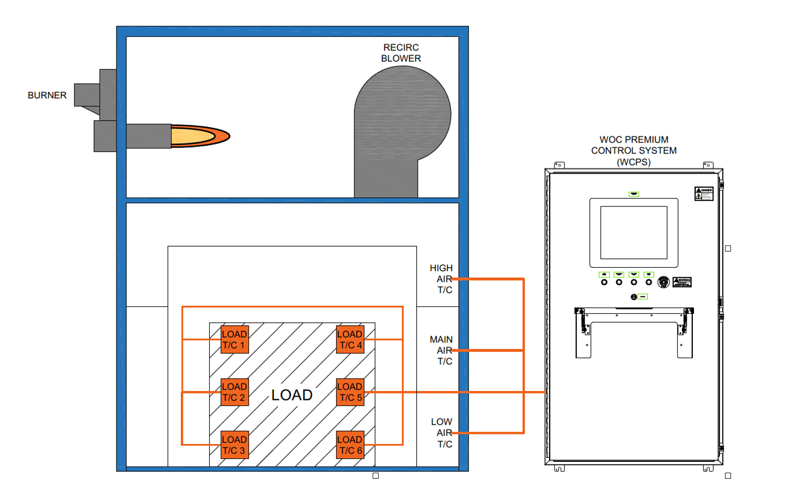
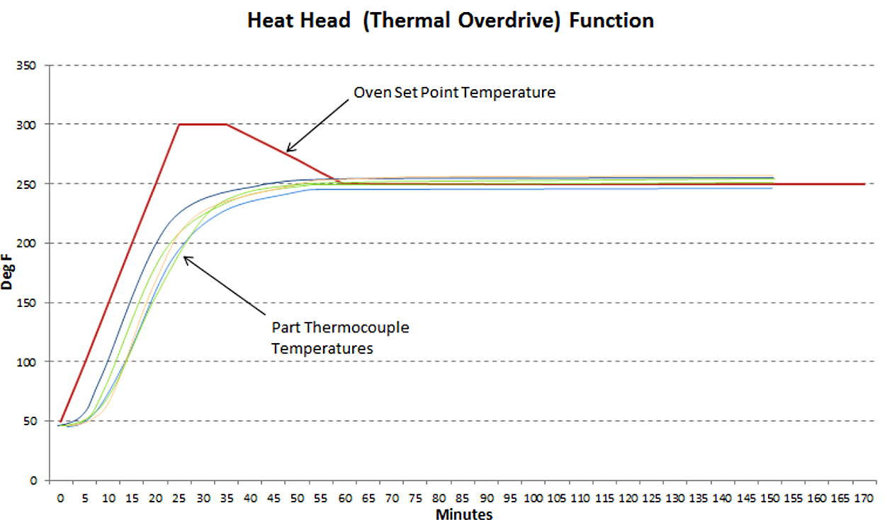
The core of the system is a PLC using special software designed specifically for vacuum bag composite curing. The temperature is controlled via input from one or more thermocouples (TCs). The TCs can be located in the heated air stream or buried in the part or both. Using leading, lagging, and averaging functions, along with thermal overdrive, the parts are heated evenly as quickly as possible without overshoot. With thermal overdrive, also known as a controlled heat head, the oven temperature is elevated for a period of time during the heatup portion of the cure cycle. This forces the part to heat more quickly than if the oven was set right at the required cure temperature. After the part temperature approaches the cure temperature, the control system automatically reduces the oven temperature to the part cure temperature. Thermal overdrive provides faster heating rates, resulting in shorter oven cycles and increased production through the equipment. (Figure 5)
In addition to thermal overdrive, the advanced control system uses the TCs buried in the part to provide a guaranteed soak, where the soak time doesn’t start until all the TCs are up to the required cure temperature, ensuring the entire part has been thoroughly cured.
Another feature important to aerospace manufacturers is that, prior to heating, the system checks the vacuum at each port for leaks. Any leaking ports will be displayed, and the operator must then either deselect the bad ports or fix the leaks and run the leak test until successful. This helps ensure no parts are processed under insufficient vacuum, which can cause defects. Monitoring of the vacuum levels continues during the heating cycle, and low- or high-vacuum levels are reported. In the same way, the system can detect a failed control thermocouple and switch control to a backup one to prevent failure of the load.
In order to meet the stringent traceability requirements of the aircraft manufacturers and others, the advanced control system continuously logs data in the background during oven operation and generates a report afterwards. When a batch is completed, the system queries the data for all information matching the batch ID, including recipe information, interval readings for the thermocouples and vacuum transmitters, alarms, and all other batch specific information. A batch report is then created that contains all this information, as well as graphs and tables related to the run and logs it into a database.
Horizontal Quench Systems, Faster Quenching than Ever
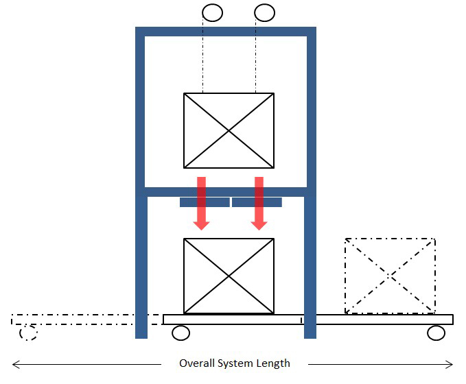
Until recently, the vast majority of aluminum solution heat treatment was performed in drop bottom furnaces. This style of furnace is elevated on legs and has a door on the bottom through which the load is quickly lowered into the quench tank below using a hoist located on top. The quench tank rides on a traveling powered car so it can be moved into place beneath the furnace for quenching. (Figure 6)
The primary advantage of drop bottom type furnaces has traditionally been a fast quench speed, defined as the time from when the furnace door starts to open until the load is fully submerged. A quench time of 7 to 10 seconds is typical, and 5 seconds is even possible for smaller loads. The disadvantages are the price of the equipment and the space requirements within the factory. Also, there is a tendency for steam to rise from the tank during quenching and become absorbed into the furnace insulation, which can cause problems.
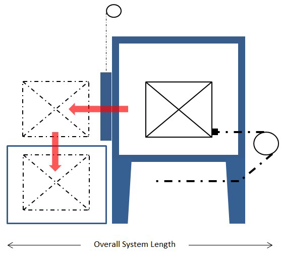
In recent years, an innovative alternative to the traditional drop bottom system has gained popularity: the horizontal quench system (HQS). In this design, the door is on the front of the furnace, as opposed to the bottom. After the load is heated, the door rapidly opens and a specially designed extractor quickly transfers the load from the furnace chamber onto the quench elevator in front of the furnace. The quench elevator then rapidly lowers the load into the quench tank. (Figure 7)
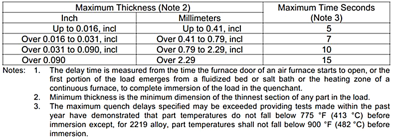
In the past, the state of horizontal quench technology was such that it was only suitable for pieces with a thicker cross section, typically cast parts, where a longer quench time is allowable. The first-generation horizontal quench systems had a typical quench time of 15 seconds or longer and could not meet the 5 to 10 seconds required for thinner materials in accordance with AMS2770 (Table 1).
Through advances in sensor and motion control technology, along with improvements in material handling techniques, the quench time for horizontal systems has progressively improved over the years. Quench times of 7 seconds are routine even for loads up to 12 feet long, weighing 3,000 pounds. This allows HQSs to meet aerospace heat-treatment requirements, while offering the advantages of lower capital cost and reduced footprint in comparison to drop bottom equipment.
With the increasing demand for aluminum horizontal quench systems, the trend is toward shorter quench times and larger loads, and the horizontal quench system is meeting these needs for the aerospace industry.


 general practice for CQI-9 and AMS2750E")


