


Increased power density in mechanical power transmission components means greater durability — allowing existing designs to achieve greater capacity or reduced size and mass for light weighting. After decades of work on adjusting gear-manufacturing practices, improving surface finishes, and changing designs to improve performance, trends are now turning toward a focus on improved performance with new gear-steel compositions and improved cleanness to enhance overall design.
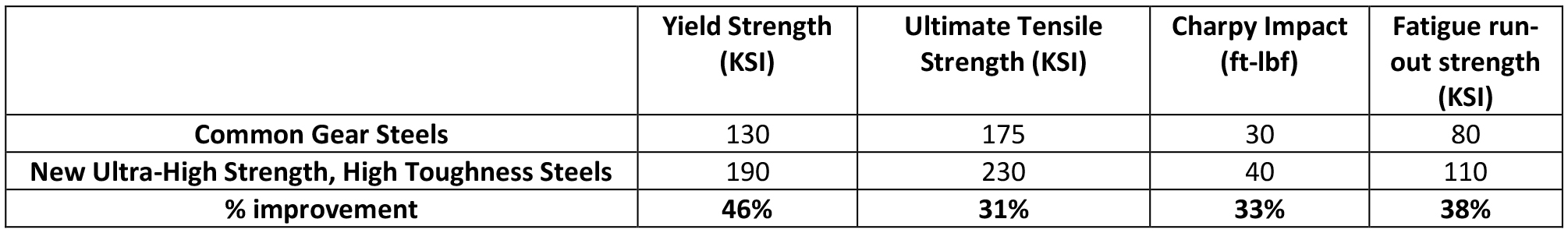
Three new ultra-high-strength, high-toughness carburizable gear steels are introduced. The new steels provide yield strengths ranging from 180-210 KSI, ultimate tensile strengths ranging from 230-250 KSI, and Charpy impact energies ranging from 35 to 50 ft-lbf, allowing these grades to provide longer life, more power and/or lighter weight. The higher fatigue strength of these steels is compared to more commonly used gear steels, and an analysis is presented illustrating a potential for either a 30-percent reduction in gear set mass, or a 45-percent increase in gear-set torque capacity.
Introduction
Carburized gear steels are often the material of choice for mechanical power transmission systems requiring excellent power density. These steels commonly have a bulk carbon composition between 0.1 and 0.2 wt.%. The near surface is carburized such that the surface contains between 0.85 and 1 wt.% carbon. Carbon is diffused in to the surface creating a continuous gradient in carbon content between the surface and core carbon composition. The steepness of the gradient can be controlled through heat-treatment processes to provide the appropriate case-carbon profile for a given application. When properly quenched and tempered, this carbon gradient results in a hard surface needed to resist bending, rolling contact and sliding fatigue, and wear damage. The moderately strong but tough 0.1-0.2 wt.% carbon core provides resistance to core bending fatigue and overload fracture.
The gradient in carbon also plays a critical role in the evolution of residual stress during heat treatment. As a result of the carbon gradient, a compressive residual stress is generated on and near the surface, further enhancing fatigue performance. As the carbon content is increased, the temperature at which martensite forms is decreased. For every 0.1 wt.% increase in carbon content, there is a reduction in the martensite formation temperature of approximately 50°F [1]. As a result, during quenching of a carburized gear, the transformation of the near surface layer is delayed to a lower temperature than the core. When martensite forms from austenite, there is a 1- to 4-percent volume expansion [2][3] (increasing with the carbon content). When the lower carbon core transforms first, the austenitic material in the case is able to accommodate the expansion through plastic deformation. Moments later, when the case transforms to martensite, the hardened martensitic core does not yield. The volume expansion in the case now results in the formation of a compressive residual stress profile near the surface. In order to optimize the evolution of compressive residual stress, a carbon gradient and associated martensite start gradient are necessary.
Increasing the carbon content of steels, when fully and properly hardened, results in higher strength, but with increased strength comes decreased toughness. These competing factors create a challenge for the gear-steel designer. In order to improve gear performance, both higher core strength and toughness are needed, as is compressive residual stress. Core carbon content has the single greatest effect on core strength and is, hence, a natural place to start toward improving gear performance. Careful use of other alloying elements is then needed to help maintain or even improve core toughness. Consideration must also be given to the evolution of residual stress and the effect of the core carbon content. The increase in core carbon content results in a decrease in the compressive residual stress. Here, the key is to only increase the core carbon content enough such that the credit gained in core strength is not offset by the debit given in residual stress.
Tables 1 to 3 show some nominal mechanical properties for existing and potential gear steels. Yield strength tends to correlate with fatigue initiation, while hardness and ultimate tensile strength tend to correlate better with fatigue strength. The last two columns show the calculated fatigue strength estimated as half of the UTS, and as a function for Rockwell C hardness respectively [4]. Charpy impact values and fracture toughness values are weakly correlated and are shown near the middle of the tables. If measured RR Moore rotating bending fatigue data is available, those data are shown as well. In all cases, values shown in red are calculated values using the equations shown at the bottom of each column.
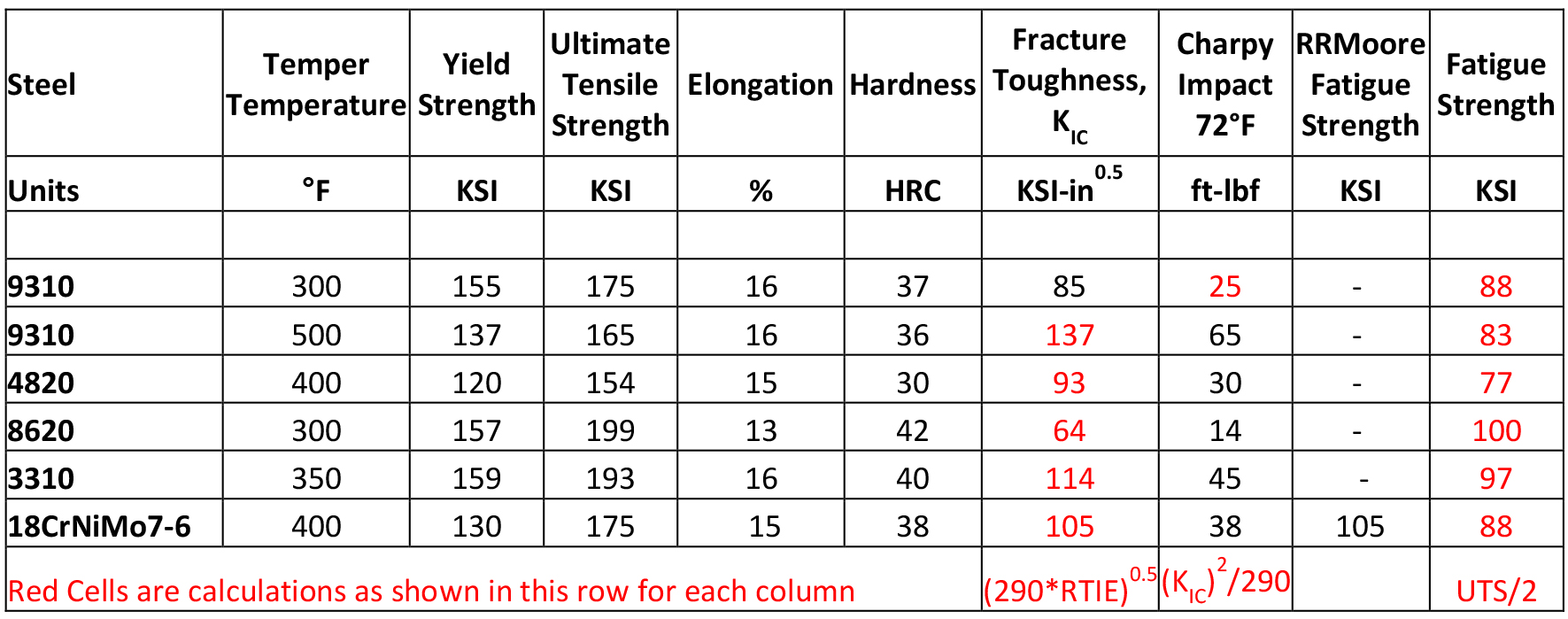
Table 1 shows nominal properties of some commonly used carburized gear steels when tempered between 300 and 500°F. Strength, Charpy impact energy, and fatigue strength values are varied, but nominal values of 130 KSI yield, 175 KSI UTS, and 80 KSI for fatigue strength are representative for this class of gear steels. Charpy impact values range from 15 to 65 ft-lbf and are inversely correlated to strength. At the nominal strength levels noted, the nominal impact energy is 30 ft-lbf.
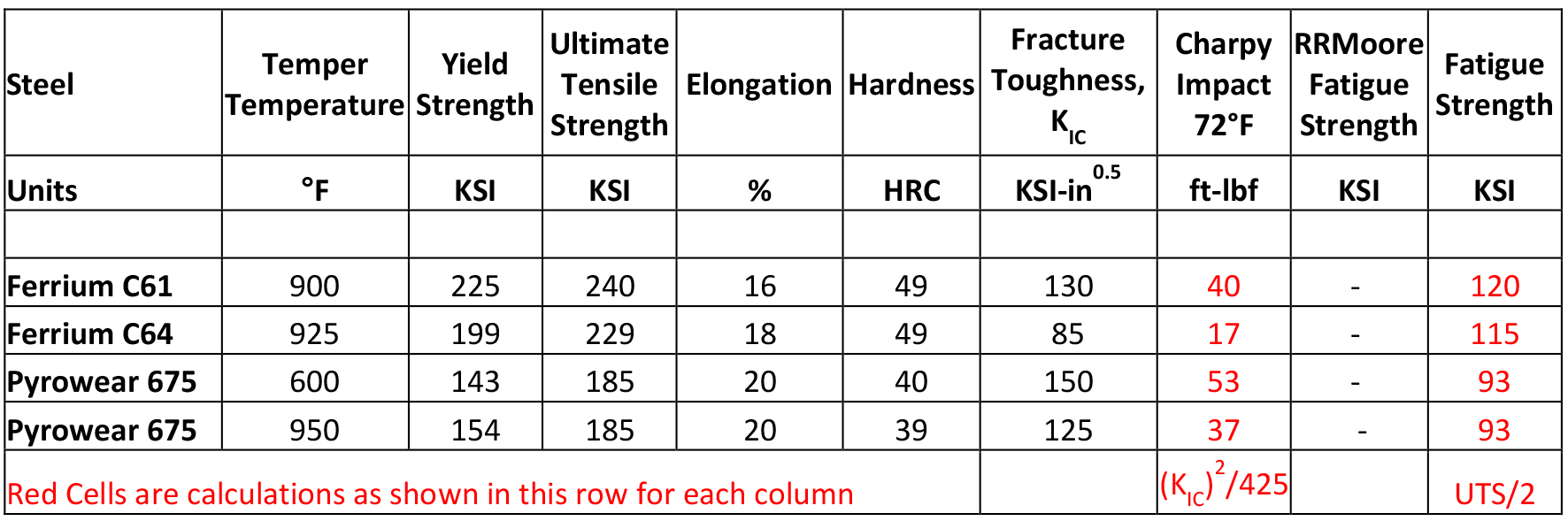
Table 2 shows nominal properties for some specialty alloys designed for use in military and aerospace applications where potential oil-out conditions exist. Here the need to escape danger while there is no remaining oil drives the need for high-temperature retention of surface hardness, core strength, and toughness. These performance capabilities are impressive, but come at a price point of 10 to 10s of dollars per pound, and so are included here as comparable examples. The remaining steels described in this manuscript, including the new ultra-high-strength, high toughness steels fall in to a price point of 1 to a few dollars per pound.
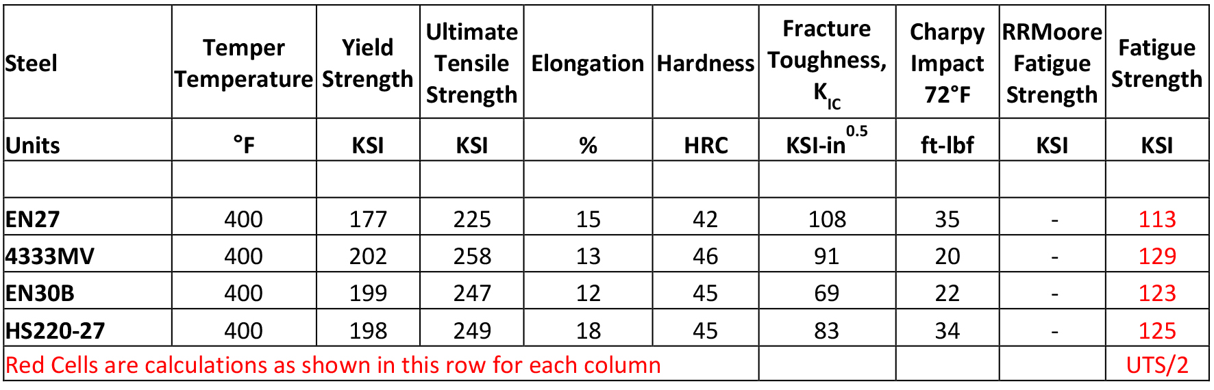
Table 3 shows the nominal properties of some ultra-high-strength steels tempered at 400°F. For these steels, the nominal carbon contents range between 0.24 and 0.34 wt.%. This carbon level falls within the range expected to provide good carburizing and residual stress response and yields increased core strength and fatigue capabilities. Here, nominal values for yield and UTS are approximately 180 and 230 KSI respectively with expected fatigue strength of 115 KSI. For these steels, the increase in strength comes at the cost of Charpy impact toughness in the range of 20 to 35 ft-lbf. While the strength and concomitant fatigue strengths are improved compared to commonly used gear steels shown in Table 1, the Charpy impact values are only on par with commonly used gear steels.
Making changes from common carburized gear alloys to new alloys consumes time, resources, and dollars. In order to justify pursuing gear steel material changes objectives of a 25-percent increase in tensile and fatigue strength, in combination with a 25-percent increase in Charpy impact energy values were targeted in developing the new steels described below. Design minimum target values of:
- 180 KSI YS,
- 220 KSI UTS,
- 110 KSI fatigue strength, and
- 40 ft-lbf Charpy impact energy (room temperature, longitudinal)
were selected.
Previous publications have described how improvements in clean-steel technology have driven the ability to provide design relevant cleanness metrics to gear designers [5]. These technologies provide affordable solutions for critical, power-dense components. The clean steels technology combines advanced electric arc melting, vacuum ladle refining and teaming practices with advanced automated scanning electron microscope (SEM)-based steel cleanness evaluation. The result is certified ultra-clean steels on par with re-melted steel and with cleanness metrics that are relevant to component design life. As strength is increased, steel cleanness becomes more critical. Steel cleanness is a critical enabling technology to fully realize the potential gains associated with these new ultra-high-strength, high-toughness steels.
Development of new Ultra-High-Strength, High-Toughness Gear Steels
A series of eight alloy steels were designed based on several factors, including a review of existing and incumbent gear and ultra-high-strength alloys, literature and patented steels, and computational thermodynamic assessment. An additional ninth alloy from a production chemistry was also included. At the time of writing this manuscript, the top-performing alloys from the test matrix have been submitted for patenting, and hence it is not possible to share full details of the chemical compositions studied. A target carbon content range of 0.24 to 0.30 wt% was selected. Carbon is necessary for strengthening, but excess carbon results in lower toughness and less favorable compressive residual stress profiles in the carburized case. The balance of other alloying elements studied for each variant were selected to optimize heat-treatment processes to maximize toughness at the target strength levels.
Six of the designed alloys aimed to achieve optimal strength and toughness when quenched and tempered at 400°F, one was designed to be quenched-and-tempered at 550°F, one was designed to be quenched and secondary hardened at 930°F, and one alloy was selected for either a quench-and-temper at 400°F, or quench and secondary harden at 930°F; 100-pound heats were produced via a laboratory scale vacuum induction melting facility using electrolytic iron and high purity alloy additions.
Residual elements such as P, Sn, and S were intentionally added at levels that simulate production levels typically achieved in electric arc furnace melted and vacuum refined steels. The 5.5” diameter ingots were forged to 2.5” square bars (reduction ratio = 3.8:1), and sample coupons were sectioned for heat treatment and mechanical testing. Coupons were normalized, quenched and tempered, or secondary hardened at and near the design optimal temperatures. Table 4 summarizes the tensile and Charpy impact properties generated from the test matrix. Three of the nine alloys met the design minimums for strength and Charpy impact energy and were down selected, provided designations as shown in the table, and prepared for further evaluation.
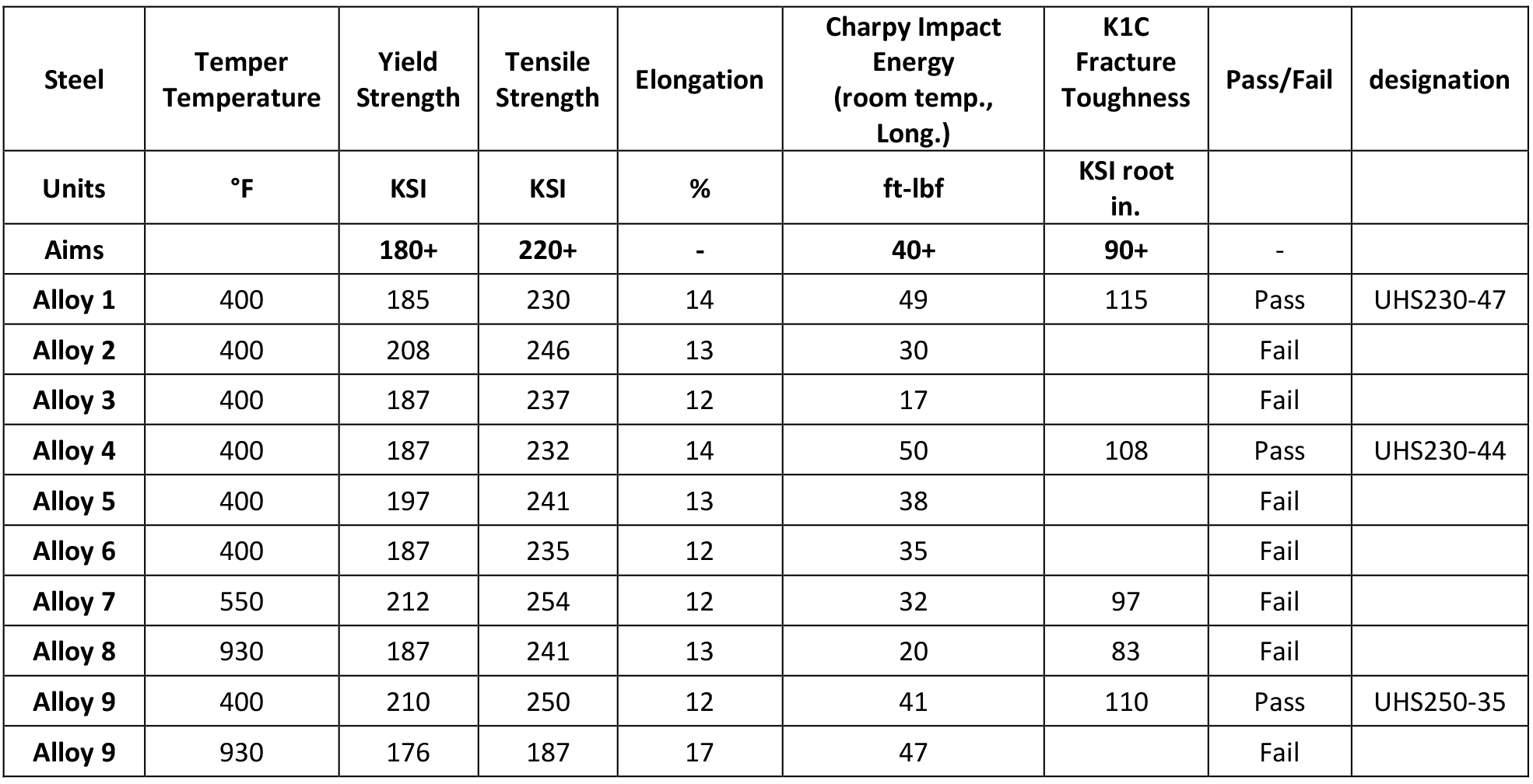
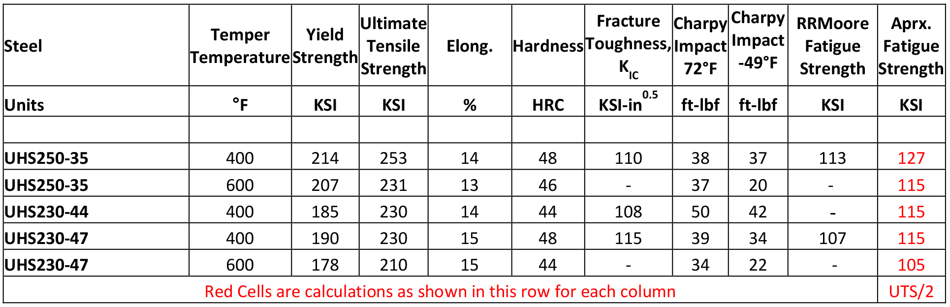
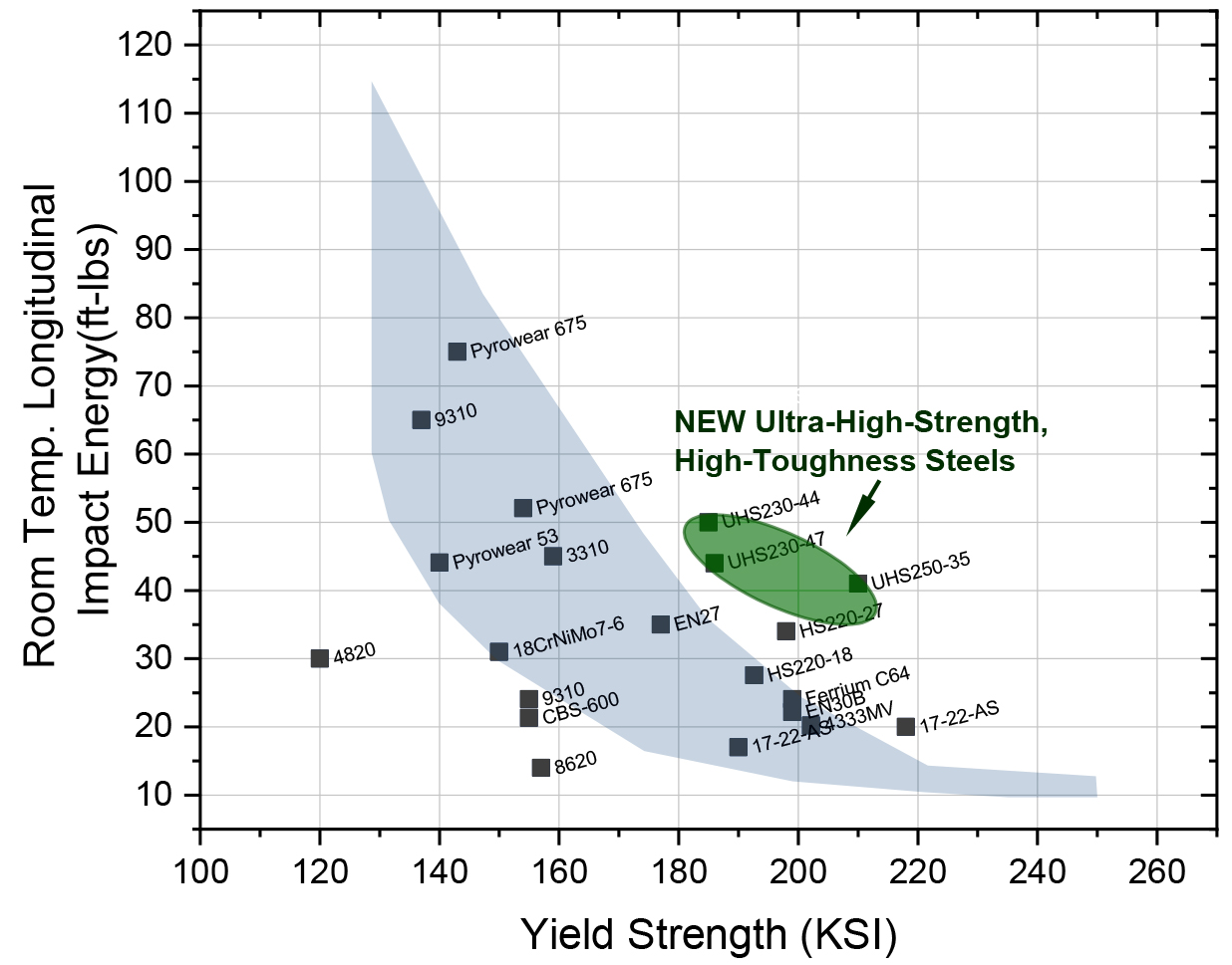
Table 5 shows additional data for the three down-selected alloys. KIC fracture toughness, -49°F Charpy impact, and U-notched rotating bending fatigue data were generated for these alloy and heat-treat conditions. Comparing these data to the incumbent carburized gear steel data shown in Table 1 shows significant improvements were achieved. Figure 1 shows yield strength vs. impact energy for incumbent alloys vs. these new ultra-high-strength, high-toughness steels. Figure 2 shows KIC fracture toughness plotted against room temperature longitudinal Charpy V-notch impact energy for this study.
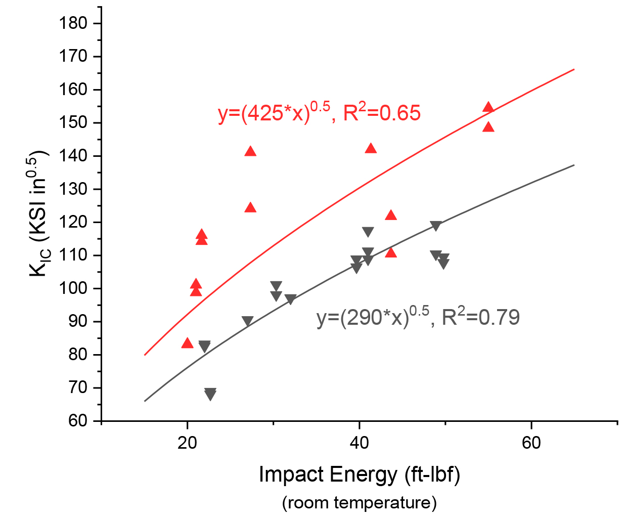
The alloys used to generate these data are those alloys shown in Tables 3 to 5. It was observed that when tempering at lower temperatures (400-550°F) the data trended differently than when tempered above 600°F. The relationships between fracture toughness and Charpy impact shown in Figure 2 are those used in Tables 1 and 2.
Standard 120-ton production heats of UHS230-47 and UHS250-35 have been produced, and 3.75”, 5.5”, 11”, and 13” bars have been hot rolled. Two heats of UHS230-44 were produced in the fall of 2018. Some of the material has been sold for initial manufacture of new products; some has been supplied to customers for trials and tests, and some remains available. Early results indicate that UHS230-47 samples are meeting requirements in section sizes up to 10”, and UHS250-35 samples are meeting requirements in section sizes up to 2.5”.
Comparative Carburization Evaluation
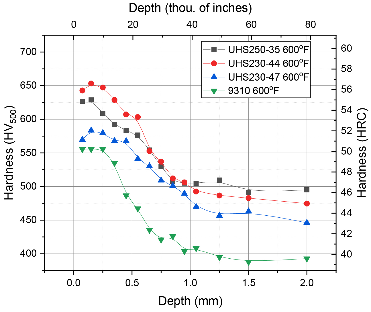
A carburization trial was performed on the new alloys and some commonly used carburized gear steels in order to develop some baseline data on the carburizing behavior of the new alloys. Steel grades 9310, 4320, and 8620 were selected for comparison. Coupons measuring 1/2” thick, 1” by 2.5” were prepared with the 1” by 2.5” face on the longitudinal rolling direction plane. The samples were carburized at 1,700°F for 4.5 hours with a 1-percent carbon potential, furnace cooled to 1,500°F and held for 0.5 hours using a 0.85-percent carbon potential, and quenched in room-temperature oil. Sets of each alloy type were tempered at 400°F and a set of the new alloys and 9310 were tempered at 600°F. These carburization data are presented as baseline data. Implementation of any new gear steel into a given supply chain or process path will require development efforts to optimize the new alloy.
When tempered at 400°F (see Figures 3 and 5), UHS250-35 and UHS230-44 exhibited similar surface hardness as 4320 and 8620 steels, a deeper case depth to HRC 50, and a higher core hardness.
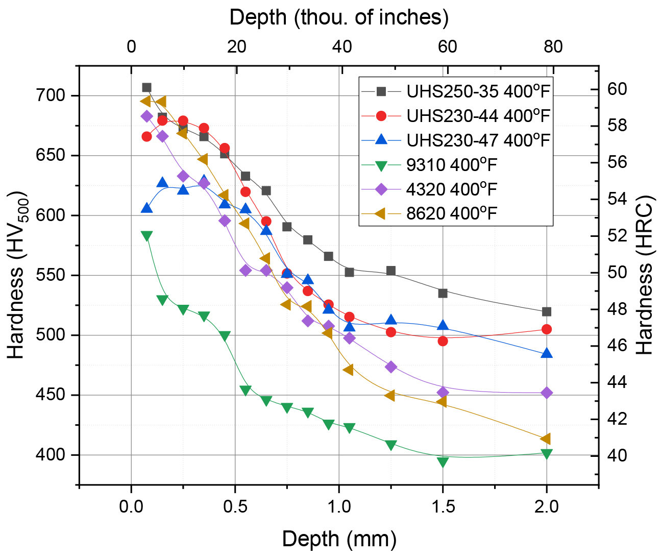
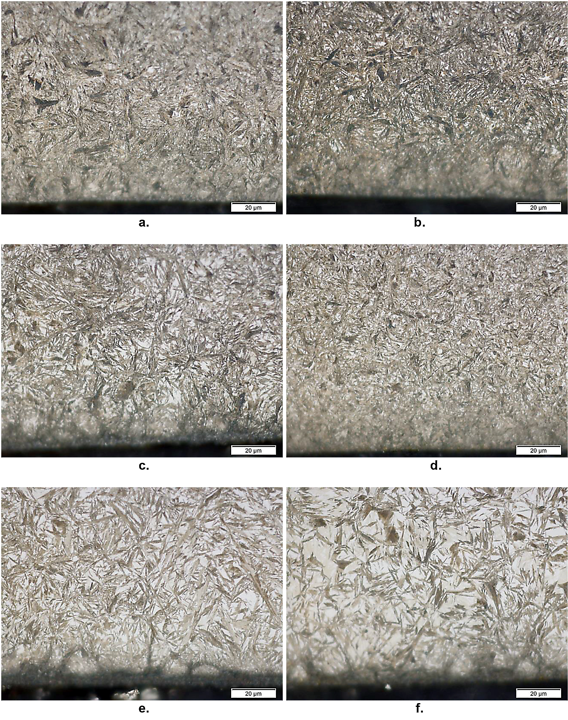
UHS230-47 exhibited a lower surface hardness compared to the other UHS-HT steels, but a higher surface hardness compared to 9310 steel. UHS230-47 exhibited deeper case depth to HRC 50 and higher core hardness compared to the common gear steels. Micrographs of the carburized structure are shown in Figure 5. The UHS230-44 alloy exhibits a slightly higher degree of grain boundary oxidation, which should be mitigated by either low pressure gas carburization, or post carburization grinding.
UHS230-47 exhibits more retained austenite near the surface which is most likely the reason this alloy exhibits a slightly lower surface hardness then the others.
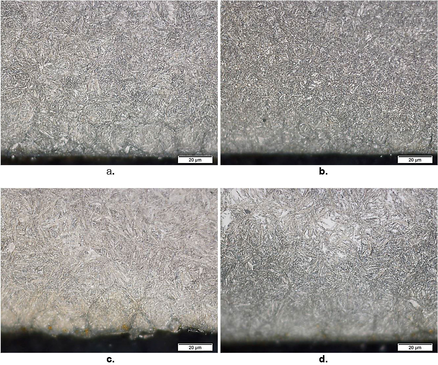
When tempered at 600°F (see Figures 4 and 6), UHS250-35 and UHS230-44 exhibited similar surface hardness to each other and a deeper case depth to HRC 50 than UHS230-47. Grade 9310 exhibits the lowest hardness profile and core hardness.
Power Densification Examples
Power Densification through Higher-Strength, Tough Steels
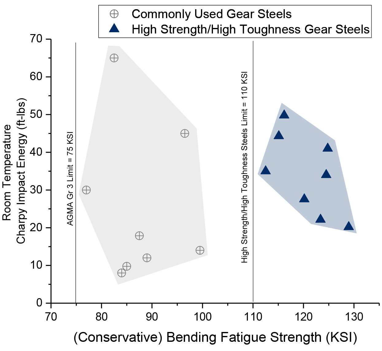
In order to assess the magnitude of the potential for either light-weighting or increased power throughput, the effects of traditional vs. ultra-high-strength, high-toughness gear steels on gear set design were assessed. The Technical Resource “ANSI/AGMA 2001-D04, Fundamental Rating Factors and Calculation Methods for Involute Spur and Helical Gear Teeth” [6] provides a framework and the equations necessary to make such estimates. In Table 4 of this AGMA resource, the allowable bending stress for grade 3 carburized and hardened gears is listed at 75 KSI. This value is also shown as the AGMA limit in Figures 7-9. The allowable limit for high-strength, high-toughness steels is also shown in Figures 7-9 at 110 KSI. In each case, for traditional and for high-strength, high-toughness gear steels, the actual fatigue capacity may be measurably higher than these conservative limits and will be further dependent on the steel grade and heat-treatment processes selected. For the sake of illustration, the bending stress fatigue limits of 75 KSI and 110 KSI were selected for further calculations.
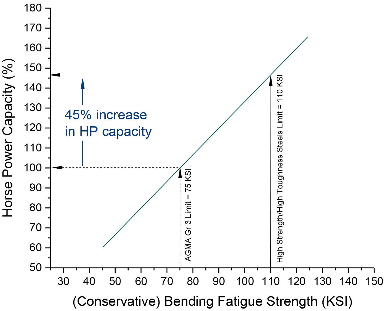
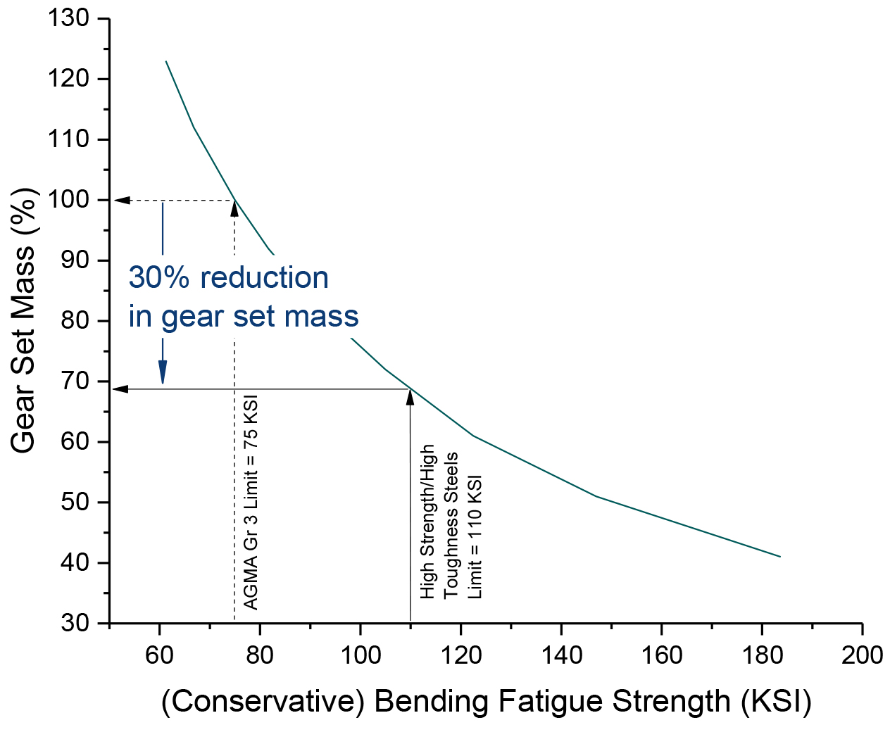
A generic pinion-and-gear set was conceived, and the calculations for this gear set were built in a spreadsheet in order to assess the magnitude of potential benefits. Figures 7 and 8 show the results of these calculations. The switch from commonly used gear steels to high-strength, high-toughness gear steels can result in a 45-percent horsepower increase. Alternatively, a 30-percent weight reduction with the same horsepower can be achieved. When a gear set design requires higher performance, high-strength, high toughness gear steels help meet the objective.
Future Work
Implementation of these new ultra-high-strength, high-toughness alloys into gearing applications is likely to follow two paths: In many cases, gear makers and users are looking for solutions to solve existing service life or design limitations. In these cases, implementation can occur on a case-by-case basis with the necessary engineering and design rigor to assure confidence in implementing these new alloys. In order to proliferate these new alloys in to gearing systems at a higher rate, AGMA and ISO standards should be updated. For gearing steel, AGMA 923 [7] a grade level 4 is proposed, which should include improved cleanness standards as described previously [5]. For gear capacity rating ANSI/AGMA 2004 [6], an increased root bending fatigue limit of 110 KSI is proposed for grade 4 steels with an ultimate tensile strength of 220 KSI or higher.
Summary and Conclusions
In order to facilitate increased gear-set durability or power density, ultra-high-strength high-toughness, low-alloy steels are proposed. Further, since implementation of new gear alloys is costly and time- consuming, a minimum improvement of 25 percent was targeted. Table 6 shows the improvement achieved in strength, toughness, and fatigue performance are between 30 and 45 percent. The improvement in mechanical properties and their effects on gear rating were assessed using the ANSI/AGMA 2001-D04 standard. For the example chosen, a 30-percent decrease in gear set mass, or a 45-percent increase in horsepower capacity are predicted.
Bibliography
- G. Krauss, 2005, Steels: Processing, Structure and Performance, 3rd ed., Table 5.1.
- J. M. Moyer, G. S. Ansell, “The Volume Expansion Accompanying the Martensite Transformation in Iron-Carbon Alloys”, 1975, Met. Trans. A, V6A, pp 1785-1791.
- L. Cheng, A. Böttger, T. H. de Keijser, E. J. Mittemeijer, “Lattice parameters of iron-carbon and iron- nitrogen martensites and austenites”, Scripta Metallurgica et Materialia, Volume 24, Issue 3, March 1990, Pages 509-514,
- Murikami, T., 2002, Metal Fatigue: Effects of Small Defects and Nonmetallic Inclusions, 1st ed., Elsevier, London.
- E. B. Damm, P. C. Glaws, “Gear Design Relevant Cleanness Metrics”, 2016, AGMA FTM.
- ANSI/AGMA 2001-D04, “Fundamental Rating Factors and Calculation Methods for Involute Spur and Helical Gear Teeth”, 2004.
- AGMA 923-B05 “Metallurgical Specifications for Steel Gearing,” 2005.
Printed with permission of the copyright holder, the American Gear Manufacturers Association, 1001 N. Fairfax Street, Suite 500, Alexandria, Virginia 22314. Statements presented in this paper are those of the authors and may not represent the position or opinion of the American Gear Manufacturers Association. (AGMA) This paper was presented September 2018 at the AGMA Fall Technical Meeting in Oakbrook, Illinois. 18FTM25


 general practice for CQI-9 and AMS2750E")


