


Heat treatment plays an important — some would say critical — role in gear manufacturing. Therefore, there is a need to better understand, from the perspective of the heat treater, the contribution of heat treatment to gear failures. Aspects such as design, material, heat treatment, and service application all provide examples that serve as an excellent platform on which to discuss different types of failure and what caused them. Furthermore, they provide heat treaters with wisdom to avoid future mistakes.
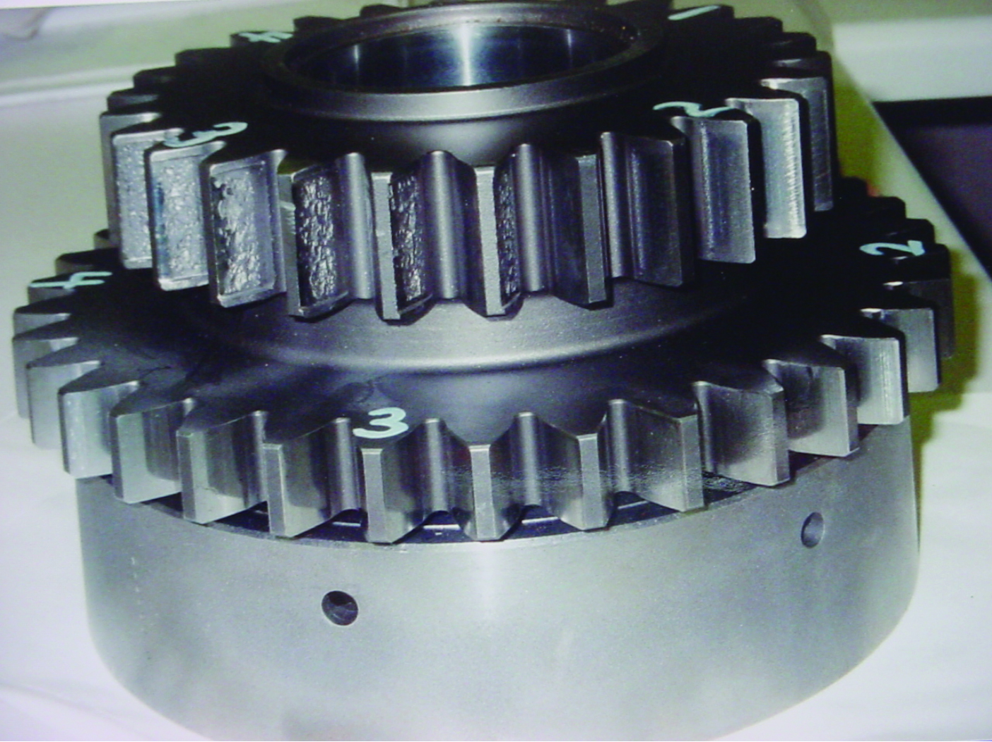
Types of Gear Failures
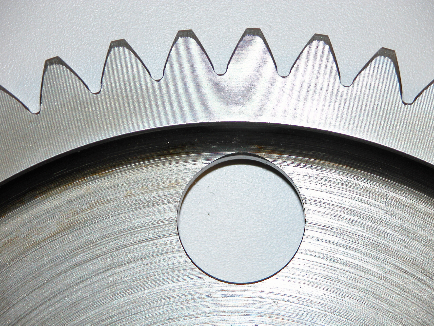
Critical failure modes for power transmission gearing include: Wear, scoring, profile pitting, tooth breakage, and spalling. In general, these can be classified into two categories: Fatigue failures and wear failures. Fatigue failures are most often associated with failures related to bending (root fillet cracks), sub-case (sub-surface) fatigue, contact (impact, stress rupture) and thermally-induced failures. By contrast, wear failures are often associated with macropitting (pitch line surface degradation) and abrasive and adhesive wear.
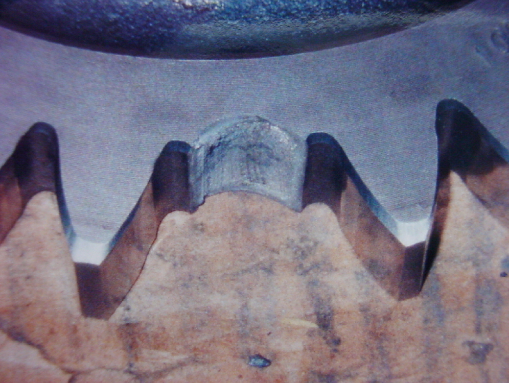
Root fillet cracks and fractured teeth failure are generally the result of cyclic bending stresses exceeding the fatigue strength of the material at the root fillet surface (Figure 1). Improper case depth, non-martensitic transformation products (NMTP) in the root microstructure, and overload conditions can cause surface cracking, followed inevitably by crack propagation to failure.
Fatigue cracking (e.g. sub-case spalling or case/core separation) starts near the case-core interface where, on the applied stress and critical strength curves, the stress exceeds the strength. The contact load induces a fluctuating applied stress gradient opposed by the critical strength gradient developed by heat treatment in the material.
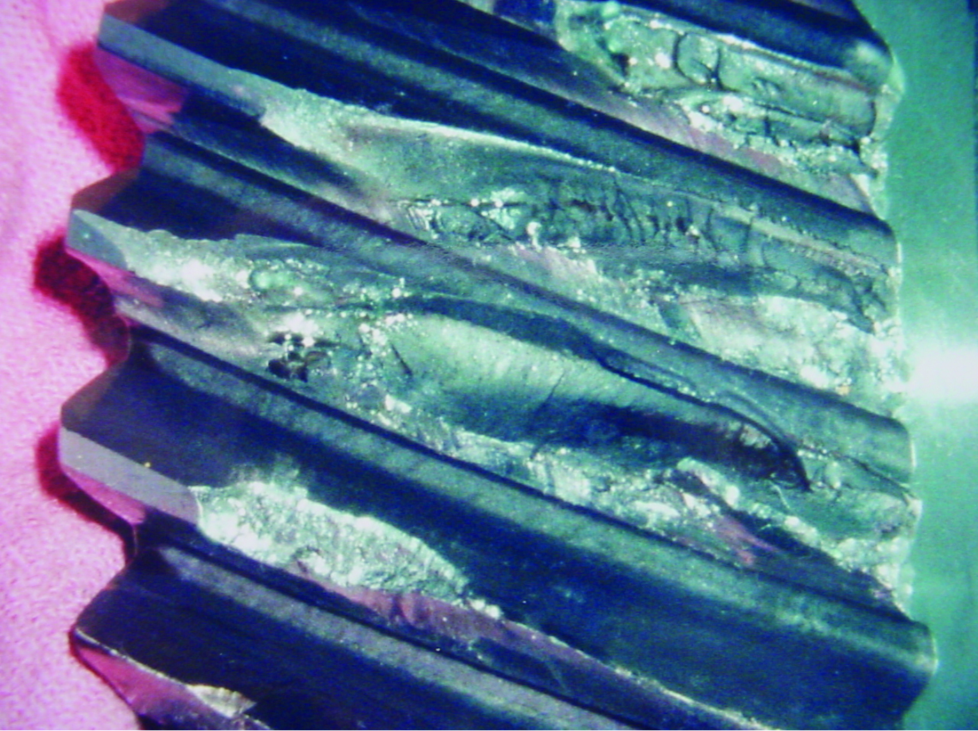
Case crushing (Figure 2) is a related phenomenon; both can be due to improper heat treatment, a high-stress concentration, or both. Case depths that are either too shallow or too deep (not leaving an adequate core to support the case) are common heat treatment-related causes.
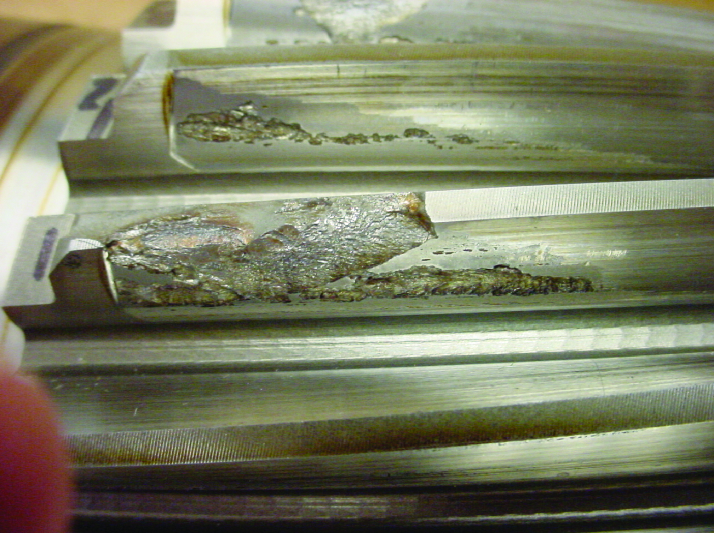
Surface or sub-surface pitting (Figure 3) occurs at the intersection of the applied (shear) stress and allowable strength at or extremely close to the surface. When sliding is present and the coefficient of friction is significant (due to poor lubrication, improper lubricant selection, or lubricant breakdown), the stress is maximized at the surface.
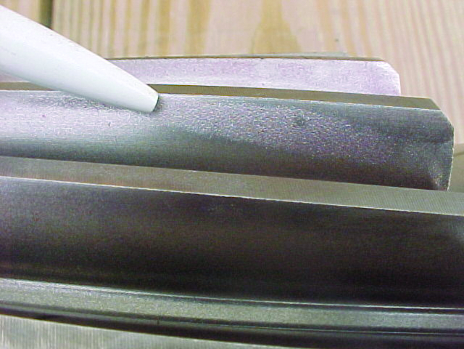
Other types of gear failures can be traced to poor heat treatment, such as shallow case depth or soft spots (Figure 4) from improper cleaning, incorrect case hardening process parameters, stop-off paint failures or from improper tempering. Poor quenching methods and improper austenitizing temperatures can also lead to inadequate hardness, with gears prematurely failing due to soft teeth (Figure 5). Material issues such as hardenability, grain size, and inclusions (Figure 6) can result in various gear failures. This underscores the criticality of steel cleanliness as well as controlling the size, shape, and type of inclusions present. Alloy segregation and banding are other issues that one can encounter in a given material, one of the reasons why normalizing is considered a prudent step in the heat treatment of gears.

Preventing Gear Failures
It is important to recognize that fatigue strength is influenced by factors such as hardness distribution (case and core hardness, case depth), microstructure (grain size, retained austenite percentage, non-martensitic phases, carbide morphology, and intergranular toughness), and by design (Figure 7) and manufacture (residual compressive stress state, surface finish, and geometry). The objective of heat treatment is to have high hardness and adequate subsurface strength on the active flank and good surface hardness and high residual compressive stress in the root area.
Case depth selection (i.e. the strength gradient) is influenced heavily by core hardness and tempering temperature. From an alloying standpoint, molybdenum and manganese strongly influence core hardness, while chromium has a moderate influence and nickel has only a weak influence. It should also be noted that the case hardness is much more sensitive than the core hardness to the tempering temperature employed (which is why tempering temperatures must be selected based on final case hardness).
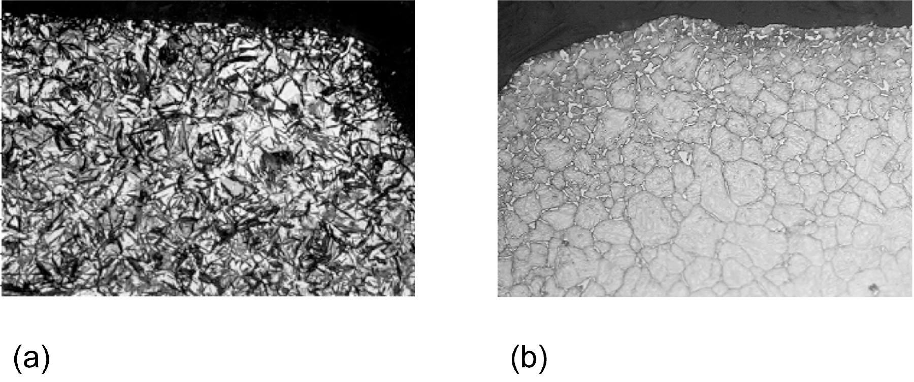
Low case hardness can also be due to carburizing with too lean a carbon potential, formation of undesirable microstructural constituents, partial decarburization of the surface, a “slack” quench, or use of the wrong tempering temperature. Variations in process parameters result in undesirable microstructures. Excessive retained austenite (Figure 8) and excessive carbide formation (Figure 8) both can lead to premature failure of the gears in service. Large amounts of retained austenite result from too high a carbon potential or direct quenching from carburizing temperature. Possible causes of carbides and carbide necklacing is, again, too high a carbon potential, insufficient diffusion time, too short a soak time, and too low a hardening temperature.
Certain gear failures can also be traced to issues with case leakage—failure of selective carburization masking methods (e.g. copper plating, stop-off paints) to protect the surface from damage. In some cases, surface contamination or improper drying will cause surface blistering. Overly aggressive blasting after plating can also damage the mask. When nital etched, unwanted carburization often appears as an irregular dark gray indication (in an area that should have been light gray).
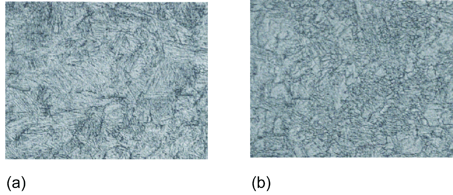
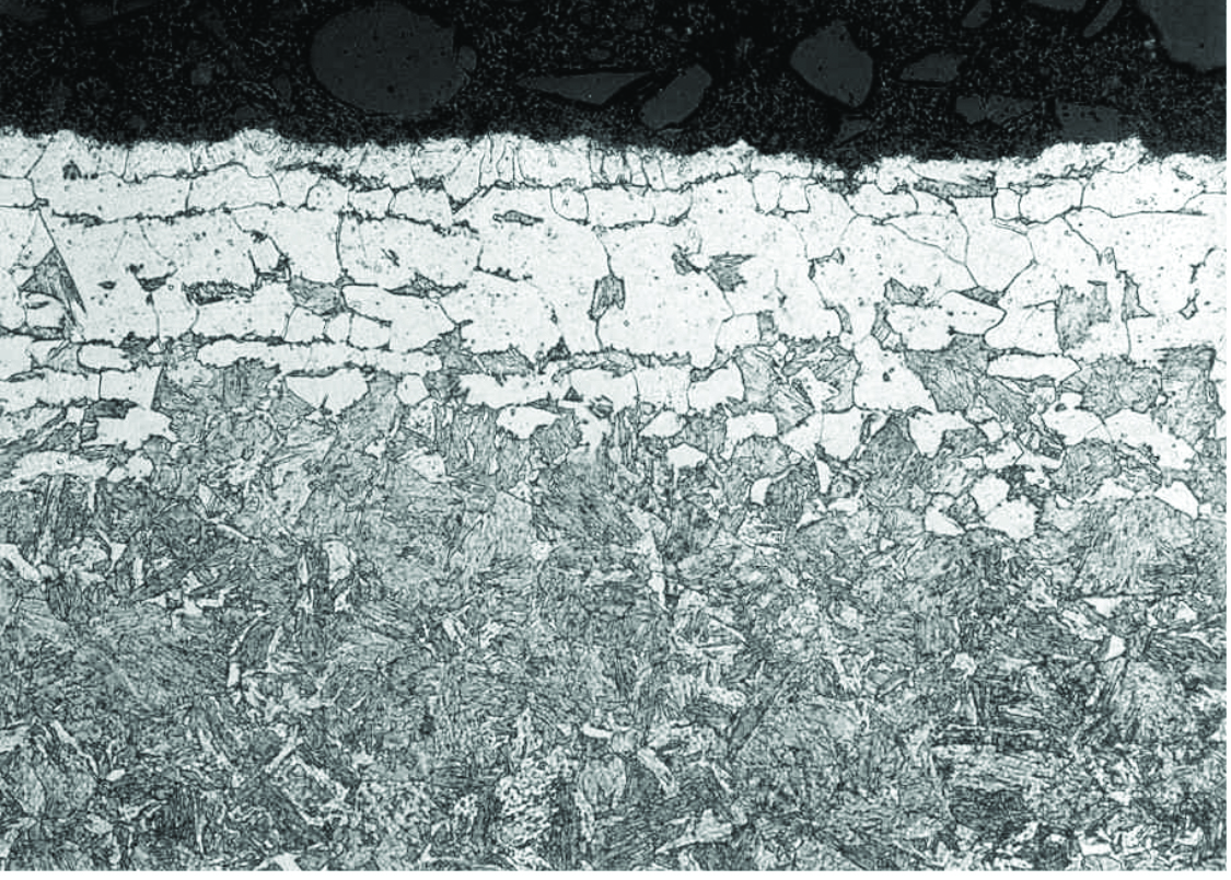
Variations in quenching, even within the same quench medium, can cause improper core microstructure and hardness. An 8822RH transmission gear was quenched at two different gas pressures (20 bar and 12 bar), resulting in differences in hardness and microstructure (Figure 9).
The condition of a particular heat treat furnace can also play a major role in premature gear life. Air intrusion into the furnace, whether through poor practices or leaks, can affect case hardness and residual stress patterns by creating partial or, in some extreme instances, total surface decarburization (Figure 10). Common reasons for this condition to exist are: Having an atmosphere carbon potential less than the surface carbon within the part, or a loss of protective atmosphere (e.g. when a power failure occurs).
Finally, the choice of carburizing method (atmosphere, vacuum) can result in differences in surface condition, intergranular oxidation (IGO), and surface dealloying due to oxidation.
Final Thoughts
Gears fail for many reasons, but failures induced by heat treatment are avoidable through good practices and tight control of process and equipment variability.
References
- Herring, D. H., How Gears Fail, SME Conference on Effective Heat Treating and Hardening of Gears, 2007.
- Herring, D. H., Case Studies – Lessons Learned, Furnaces North America, 2012.


 general practice for CQI-9 and AMS2750E")


