


Controlling the induction-hardening process is a demanding application compared to most other thermal processes. The first and foremost requirement is to precisely control the energy delivered to the part in a reliable and repeatable manner and to deliver that energy to a precise location within the part to assure that the heat-treat pattern is per the specifications. The challenge with induction hardening is that the time elements are measured in seconds and fractions of seconds, and the power densities are measured in 10s of kilowatts per inch squared, in some cases raising the surface temperature of the part at rates as much as 2,200°C/s (4,000°F/s) or higher to a temperature accuracy typically better than 2 percent. Temperature rises at this rate occur in rapid scanning operations, for example 10.16 cm/s (4 inch/s) scan rates with a 2.54 cm (1 inch) long coil, or with small parts with shallow case depths in static heating operations where the heat times can be 0.5 seconds or less.
Equally critical is the precise control of the quenchant to cool the part at the required rate to obtain the desired metallurgical structure. Also, this process control must be implemented in a noisy electromagnetic environment generally in concert with complex and rapid machine control functions and with an independent process and part monitoring system to assure product quality. This makes control of the induction-hardening process one of the most challenging industrial control applications.
Effective systems of quality control/quality assurance are essential for modern-day heat-treating practices. The essentials of an effective control program include:
- An independent quality assurance department.
- Standards of quality that reflect customer needs.
- Written procedures covering all phases of the heat-treating process, starting with prototype qualification through inspection approval for shipment.
- Process control documentation.
- Methods of maintaining part identification through heat treating and keeping written inspection records.
- Inspection procedures including frequency sampling, and identification and segregation procedures for nonconforming products.
- Schedules for calibration of test equipment.
- Schedules and procedures for record retention.
- Identification of training needed and implementation of training programs.
- Systems for control of documentation including review and distribution.
- Periodic audits.
The production of a system that meets the metallurgical specification at a production rate that meets the requirements of the customers when dealing with small time increments requires the control designer to consider all elements of the system, including the time response and characteristics of the proper controls and also the characteristics of the external elements of the system such as power supplies, valves, motion controllers, pumps, and so forth. Controls requirements can range in complexity from a small lift rotate machine with 5 kW or less of power and a single motion that can be controlled with a simple small programmable logic controller (PLC), to sophisticated oil industry quench-and-temper lines that may be distributed over hundreds of feet, include up to 10 discrete individual machines, and have 10s of megawatts of power, multiple drives, PLCs with multiple proportional-integral-derivative (PID) loops and computers, and include distributed or Ethernet IO.
All elements of the control design are critical — from the approach to the ladder logic needed to properly, reliably, and safely control the process, to the machine wiring having proper grounding and separation of power leads from control leads, low-signal-level wiring from higher-signal levels, and isolation of servo controls from all other signals.
The control designer must also consider the manufacturing procedures and environment that will exist in the final equipment installation. If the machine is to be installed in a job shop environment where only one or two operators will be responsible for the machine and will understand the characteristics of the process and the machine, the control design can be simpler than if it will be installed in a major production environment where the machine will be operated by multiple operators who basically are unfamiliar with the operation and controls. The system then must be “foolproof.”
Another consideration is whether the machine will be installed in a facility that is unfamiliar with the induction-hardening process. Many operators will recognize that increasing the power level will increase the case depth, but they may not realize that an equally similar change in the heat time possibly caused by a change in the machine functioning will have the same or a similar effect on the process. The goal is to control energy, which is the integral of power and time, whether it is the heat run time with a static application or a change in scan speed in a scanning application.
Process monitoring with an independent monitoring system is common in many applications, especially in the automotive industry. The preferred method of monitoring should be as physically close to the end process as possible. For instance, voltage and current feedback from the coil terminals can be fed to both a signature monitoring system and an integrating circuit to produce a signal proportional to coil energy. Monitoring at the coil eliminates power circuit variables such as loose bolts and deteriorating load matching components such as capacitors and transformers. It is also prone to secondary variables. Integrating circuits for high-frequency applications are often sensitive to temperature variations of the integrating circuit components and can drift during the process, causing variations not related to the process. Although many suppliers have resolved these issues, most have migrated to coil volts squared as energy to the load measured. This greatly reduces the variables, is less expensive, and is much less error prone.
Process monitoring is a necessary quality requirement, but what many customers overlook is the diagnostic contribution of the process monitors. If the data is recorded and stored for each cycle, preferably energy and a signature, it becomes a powerful tool to diagnose process variations or to review the cause when out-of-specification parts are observed downstream from the heat-treating equipment. If the data is available, it can be analyzed after the fact for process variation. In this regard, the preferred data is a signature from each cycle. Very few operations have the skilled personnel or the tenacity to use signature monitoring as a quality accept-reject parameter. However, as a diagnostic tool, it is powerful, and those that use it find it reduces the cost of destructive testing considerably.
Typical automotive heat treating specifications such as the AIAG Specification CQI-9, “Special Process: Heat Treat System Assessment, 3rd Edition”[1], and the Ford W- HTX heat treat specification [2] have not allowed the replacement of destructive testing with monitoring processes, but suppliers have been successful with approved self-assessment programs to replace destructive testing with proven monitoring techniques.
Process Control Modes
Control modes for heat treating discrete automotive, truck, or off-highway parts are typical in an open-loop mode (no feedback loop), either set up on a scanner as a power level and scan rate or in the dwell mode for static applications as a power level and a heat time. The open-loop control then depends on the power supplies for the closed-loop control (feedback to a set point) to assure that the power level requested is the power level delivered. The common modes are closed-loop control at constant voltage, constant power, or constant current.
The basic elements of control design are safety, process control, process verification, machine control, productivity, repeatability, and ease of setup. The controls for the more common types of induction hardeners include:
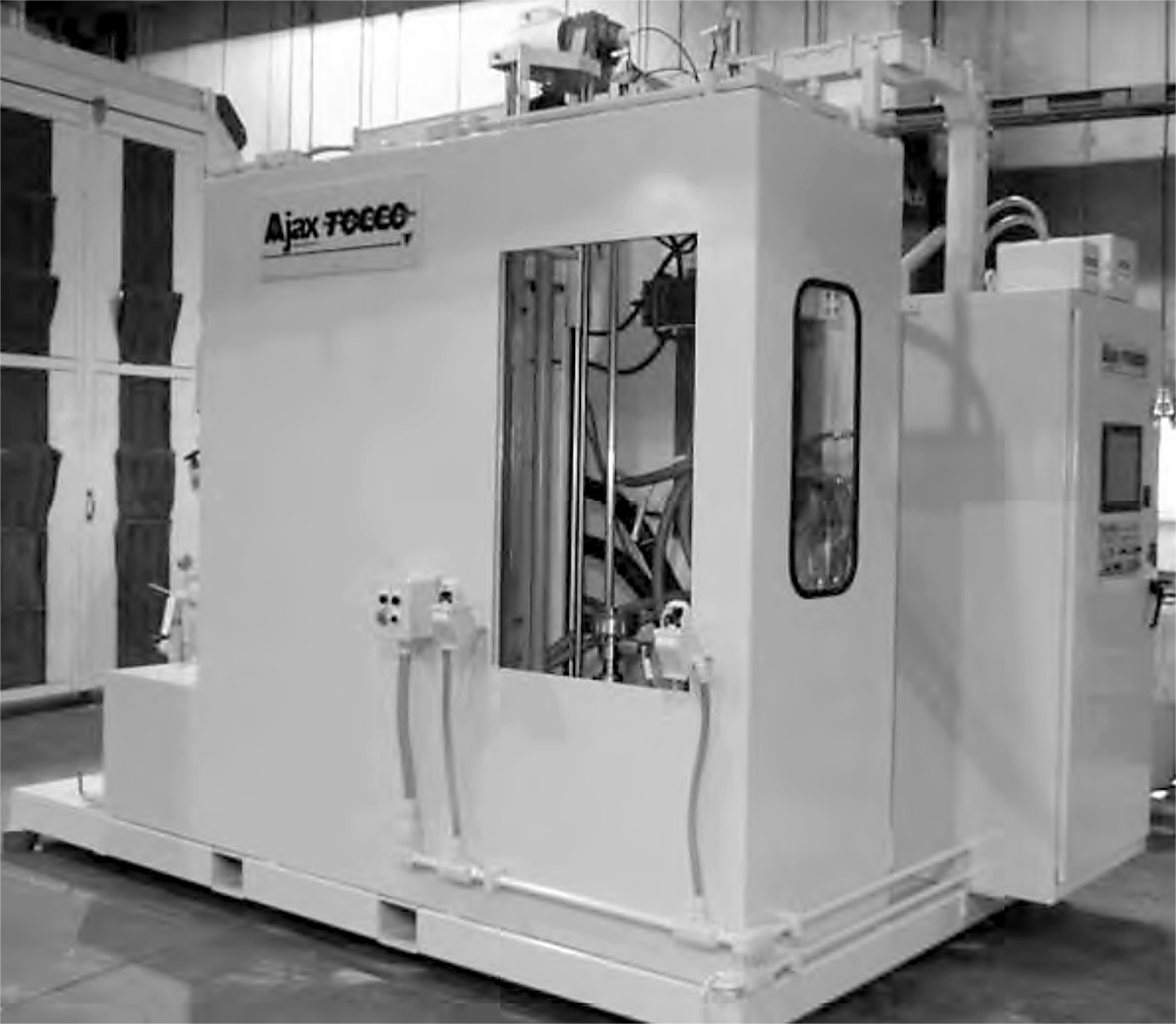
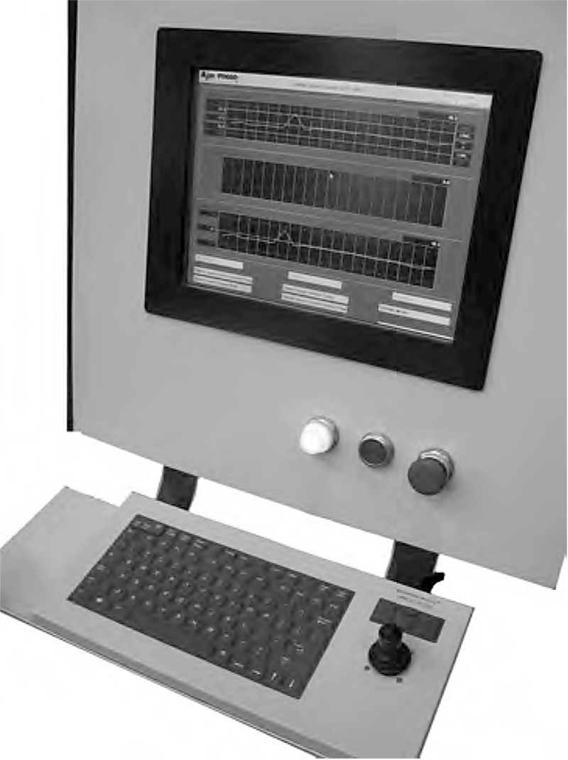
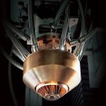
Scanner Systems: Scanners are widely used for induction heating. Scanners are very versatile and can be used for either vertical or horizontal applications. Typical scanners are either servo or computer numerically controlled (CNC), which allows for accurate position, speed, power, rotation, and quench control. See Figure 1 and 2 for an example of a scanning system and controls.
Lift and rotate systems: These can range from simple, single-position mechanisms that permit out-of-the-coil loading with the part to be heated either lifted or dropped into the coil. Quenching can be done within the coil or out of the coil.
Static Heating Systems: Static heating machines provide no part movement. The part is placed in or in proximity of an induction coil. The part is heated and quenched in place.
Process Monitoring Requirements
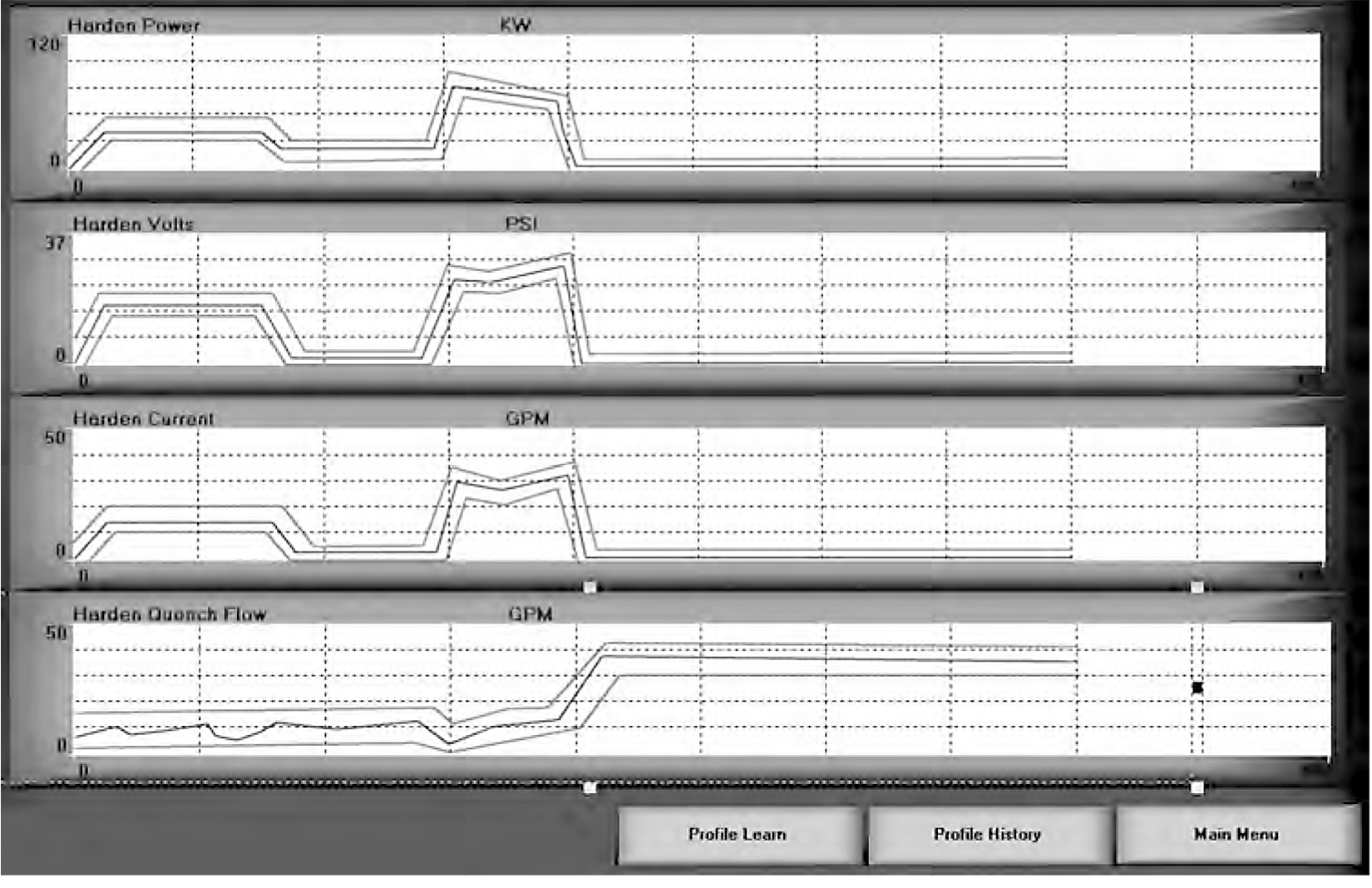
The system requirements vary with different induction processes and requirements. Figure 3 shows the process signatures of some items that require control and may require monitoring.
Metallurgical Destructive Testing vs. Monitoring
A case can be made that if all process parameters are monitored accurately, then destructive testing can be greatly reduced. In-line inspection still has problems with false indications of faults, and with items such as automotive safety parts having a requirement of no defects, some destructive testing is still recommended. This monitoring incorporates all the previous items discussed.
Key factors that affect metallurgy in induction heating are the amount of power transferred to the part, the length of time the power is transferred, the amount of quench applied, the time duration of quench, and the time between end of heating to start of quenching. Changes in the power will produce parts that have a shallow case, deep case, and so forth. Changes in the quench will produce parts with varying hardness readings. If these variables can be controlled and monitored accurately, then the need for destructive testing can be reduced or eliminated. These factors, along with the normal tight control of material hardenability and structure, and quench concentration and temperature, will produce total control of the process.
Programmable Logic Controllers
Programmable logic controllers (PLCs) have evolved greatly in the past few decades. Early generations allowed very simple programming basically replacing relays. Ladder logic was mostly limited to normally open or normally closed contacts and outputs. This mimicked the operation of relays and the ladder logic was similar to relay wiring diagrams, making it much easier for technicians to adapt. As PLC computer technology advanced, so did PLCs, from very basic to very sophisticated units. As math functions became available in the PLC as well as hardware advancements, PLCs became much more efficient in machine control and monitoring. Now instead of simply being able to monitor the on-off state or only have control of on/off states, designers have an array of possibilities.
References
- “Special Process: Heat Treat System Assessment, 3rd Edition,” AIAG CQI- 9, Automotive Industry Action Group, 2011.
- “Control of Heat Treating Processes and Auxiliary Equipment,” W-HTX, Ford Manufacturing Standards, Ford Motor Company, www.pbr.com.au/supplier/documents/ControlofHTProcessesW-HTX.pdf (accessed October 30, 2013).


 general practice for CQI-9 and AMS2750E")


