


 Even though the price of natural gas is currently low, the investment in high-efficiency gas burners makes sense economically. This article discusses different types of high-efficiency gas burners and radiant tubes now on the market. It will also explain the tradeoff between efficiency and NOx emissions and highlight a combustion technology which makes it possible to have the best of both worlds. Finally, the article will discuss a correction factor which can be used to adjust NOx emissions limitations based on combustion efficiency.
Gas Burner Technology
The graph depicted in Figure 1 shows combustion efficiency (based on the lower heating value) as a function of exhaust gas temperature prior to the heat exchanger (if one exists for a particular burner type). In the case of a direct-fired burner, this is equal to the temperature of the furnace. In the case of a radiant tube burner, this temperature is higher than the furnace temperature by an amount which is related to the heat flux density across the radiant tube (cf. e.g. [1]).
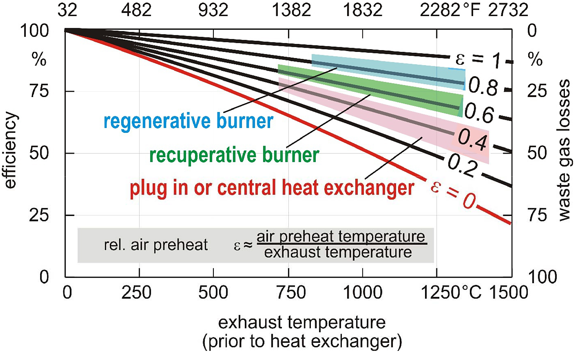
The curve labeled ε = 0 represents a cold air burner (i.e. no combustion air preheat). At a temperature of 1,832 degrees F (1,000 degrees C), the best possible efficiency for this type of burner is approximately 50 percent. Many older cold air burners have an efficiency that is even lower than the theoretical maximum due to a variety of factors such as burner design, lack of maintenance, and improper tuning.
The curve labeled ε = 0.4 represents a burner equipped with either a plug-in recuperator or a central heat exchanger. In this case, the combustion air is pre-heated to approximately 40 percent of the exhaust gas inlet temperature. At the reference temperature of 1,832 degrees F (1,000 degrees C), this burner type has an efficiency in the range of 60 to 65 percent.
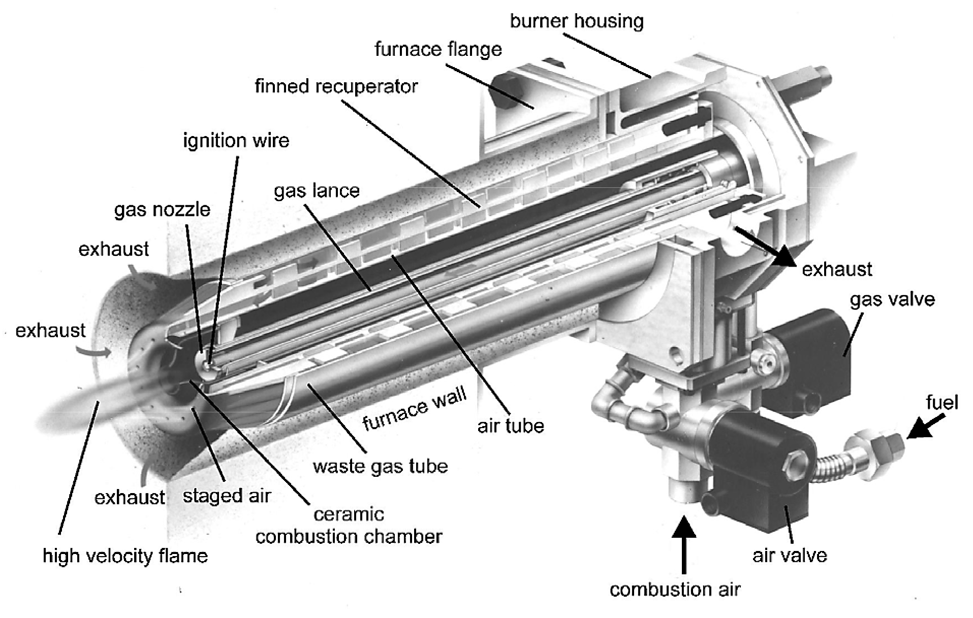
The curve labeled ε = 0.6 represents a self-recuperative burner. With this burner type, the heat exchanger is an integral part of the burner, and it sits directly inside the wall of the furnace. This arrangement helps to minimize heat losses to the ambient and thereby provides increased efficiency. In this case, the combustion air is preheated to approximately 60 to 65 percent of the exhaust gas inlet temperature. At the same reference temperature of 1,832 degrees F (1,000 degrees C), this burner type achieves an efficiency in the range of 70 to 75 percent. Self-recuperative burners are available with either a metallic or ceramic heat exchanger. The metallic type can operate at temperatures up to approximately 2,050 degrees F (1,120 degrees C), whereas the ceramic type can typically operate at temperatures up to approximately 2,372 degrees F (1,300 degrees C). Figure 2 shows a cross-section of a self-recuperative burner.
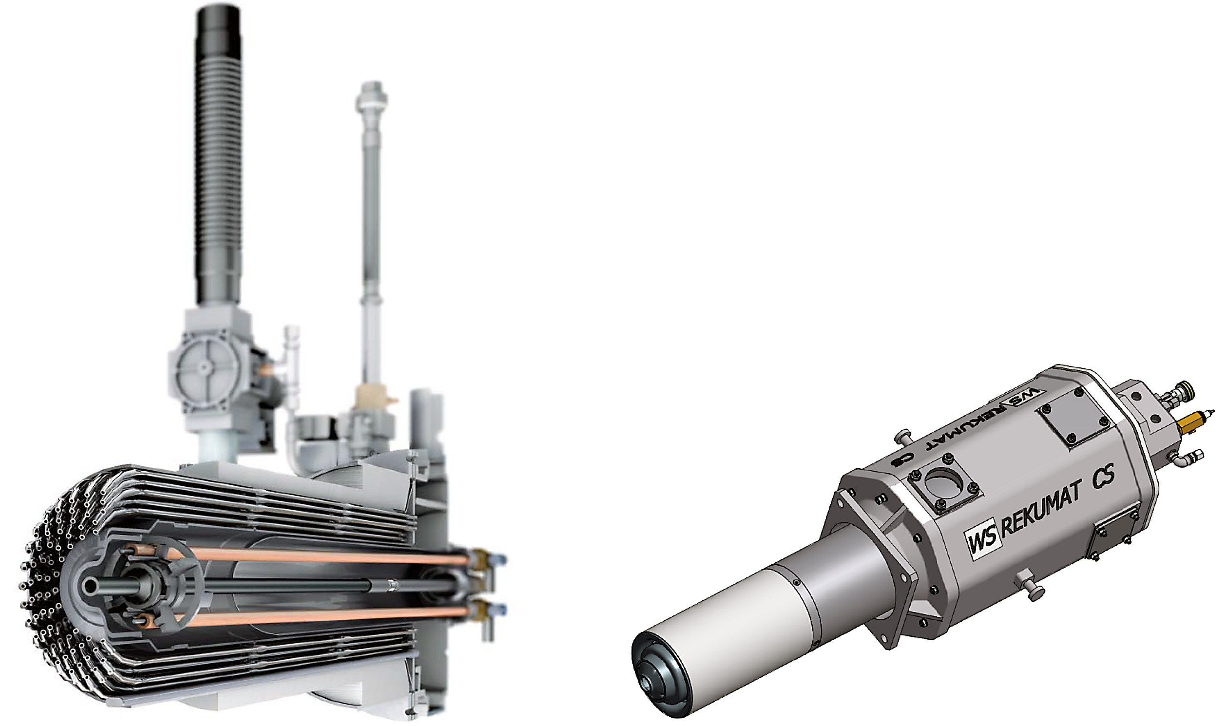
There is a new generation of self-recuperative burners which does not fall within the typical range depicted in Figure 1. This burner type is known as “gap flow.” With this design, the burner is equipped with many tiny tubes that serve as heat exchangers. This configuration effectively triples the heat transfer surface area, thereby increasing combustion air preheat to 75 to 80 percent of the exhaust gas inlet temperature. At the reference temperature of 1,832 degrees F (1,000 degrees C), this burner type has an efficiency in the range of 80 to 85 percent. It is available with either a metallic heat exchanger or a combination of a ceramic and a metallic heat exchanger. The metallic type can operate at temperatures up to approximately 1,832 degrees F (1,000 degrees C), whereas the ceramic/metallic type can operate at temperatures up to approximately 2,300 degrees F (1,260 degrees C). Figure 3 shows typical metallic and ceramic/metallic gap flow burners.
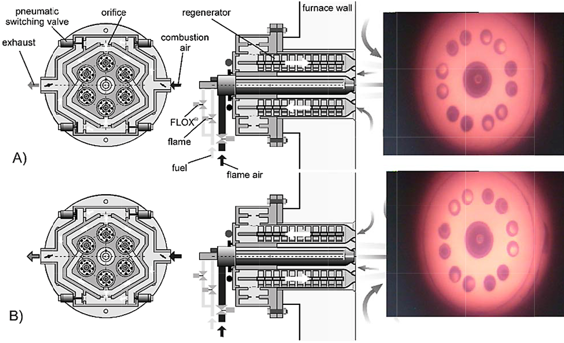
The curve labeled ε = 0.8 on the graph represents a regenerative burner. This burner type is equipped with heat storage media such as ceramic balls, discs, etc. Heat storage media is therefore in direct contact with either hot exhaust gas or cold combustion air depending on the point in the regeneration cycle. In the first half of the cycle, the hot exhaust gas heats the storage media to a very high temperature. Then switching valves are activated, and the flow path is reversed so that cold combustion air now flows over the heat storage media. With this arrangement, the combustion air is pre-heated to approximately 80 to 85 percent of the exhaust gas inlet temperature. At the reference temperature of 1,832 degrees F (1,000 degrees C), this burner type has an efficiency in the range of 85 to 90 percent. Traditional regenerative burners fire in pairs – one burner fires while the other exhausts and vice versa. A newer type known as the self-regenerative burner integrates all the regenerators and switching valves into one self-contained unit. Each burner contains six passageways, and each passageway contains a row of ceramic honeycomb discs that serves as the heat storage media. At any point in the cycle, three passageways are exhausting, and the other three passageways are admitting combustion air. After about 10 seconds, the switching valves cycle, and the flow path is reversed. Regenerative burners are also available in either metallic or ceramic varieties. The metallic type can operate at temperatures up to approximately 1,832 degrees F (1,000 degrees C), whereas the ceramic type can operate at temperatures up to approximately 2,372 degrees F (1,300 degrees C). Figure 4 shows a cross-section of a self-regenerative burner.
Radiant Tubes for Indirect Heating
In many cases, gas burners fire directly into the furnace chamber. In a number of cases, however, the process requires that work load not be exposed to the products of combustion. For example, some processes require a protective atmosphere, such as nitrogen, to prevent oxidation on the surface of the parts. In these cases, indirect heating is used. One method of indirect heating is to fire the burners into radiant tubes which, in turn, transfer heat to the furnace and work load by virtue of a temperature differential.
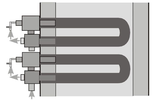
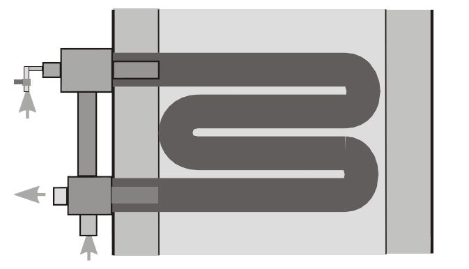
Cold air burners, or those that use either plug-in recuperators or a central heat exchanger, are paired with traditional, non-recirculating type radiant tubes. With this tube type, the burner fires into one end of the tube and exhausts out the other. Examples of this tube type are the U-tube and the W-tube (see Figures 5 and 6).
Self-recuperative and self-regenerative burners are paired with recirculating type radiant tubes. These tubes each provide some sort of path for internal recirculation, and the burner fires into and exhausts out of the same end of the tube, leading to improved temperature uniformity over non-recirculating tubes.
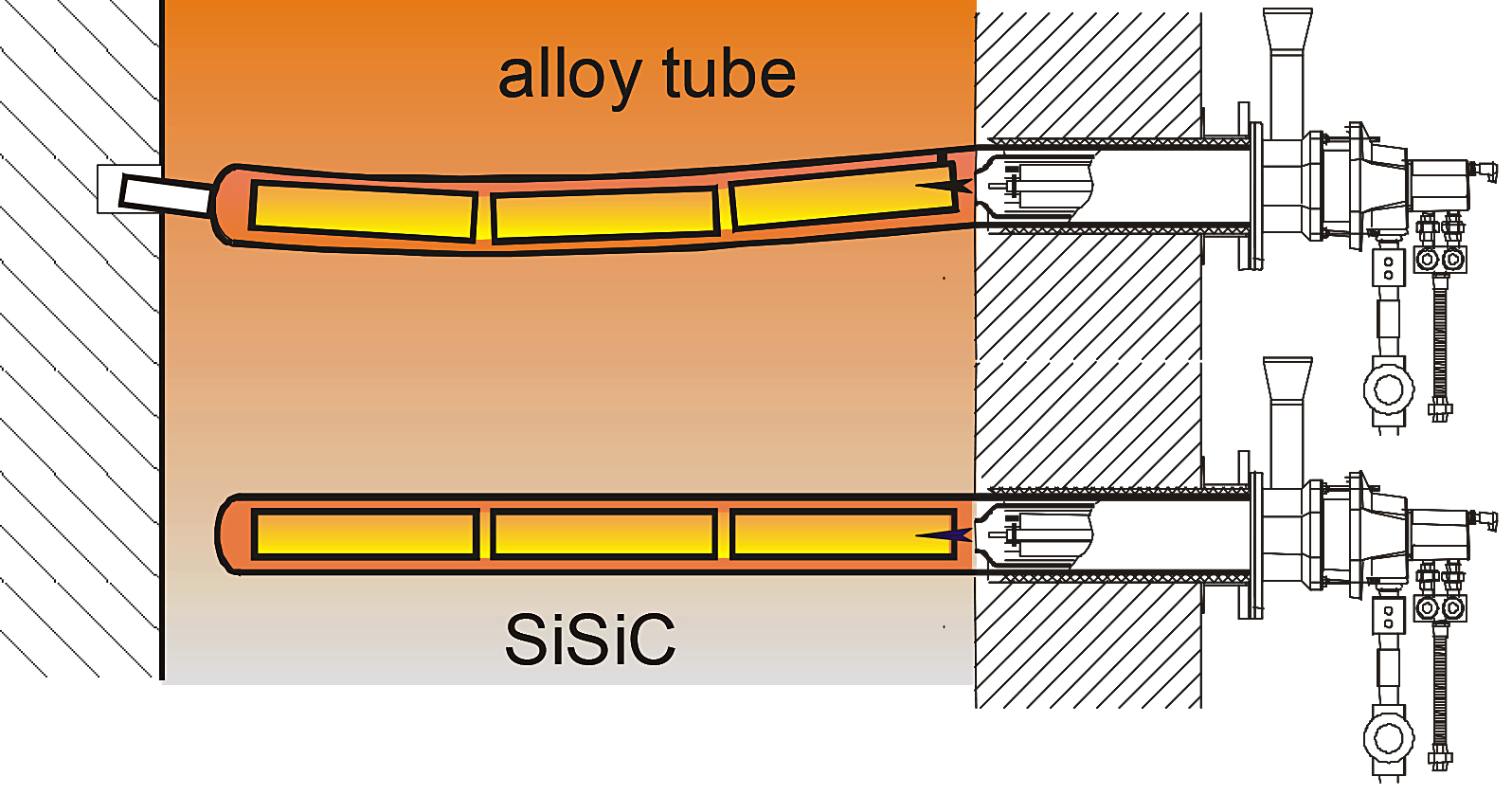
In the case of a single-ended radiant tube (see Figure 7), exhaust gases flow through an inner tube and then back toward the exhaust through the annulus between the inner and outer tubes. There is a critical space between the tip of the burner and the beginning of the inner tube assembly. The exhaust gases reach this point, and the high velocity burner jet creates a Venturi effect to draw a portion of the exhaust gases back into the inner tube. In this way, the exhaust gases are recirculated several times before they finally pass over the heat exchanger and out of a port on the burner.
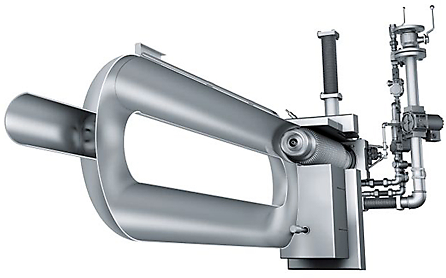
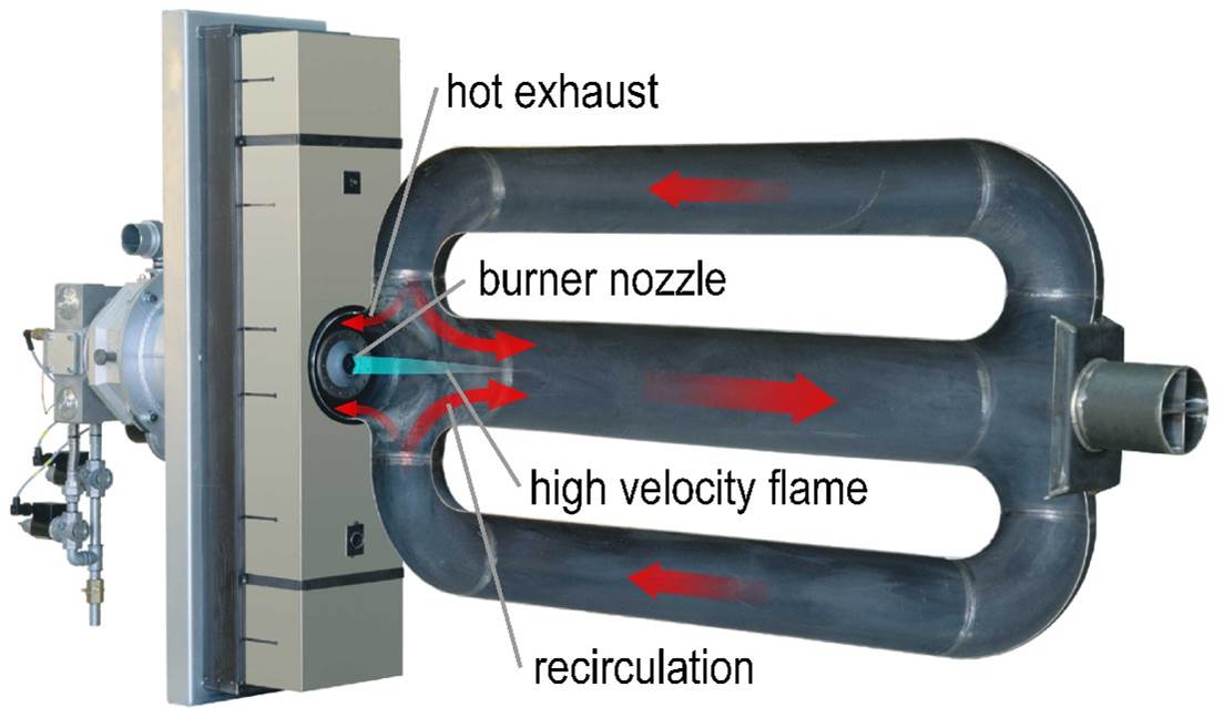
A P-tube (see Figure 8) is similar to a U-tube, except that it has a cross-connecting piece to promote internal recirculation. The burner fires into one leg of the tube, and exhaust gases flow back through the other leg and into the cross-connecting piece. The high velocity burner jet creates the same Venturi effect to draw a portion of the exhaust gases back into the firing leg. Likewise, the exhaust gases are recirculated several times before they finally pass over the heat exchanger and out of a port on the burner.
A Double P-tube (see Figure 9) is like a P-tube, but it has two return legs. In this arrangement, the burner fires into the center leg and the exhaust gases flow back through the side legs. This tube type provides a larger surface area and is therefore used with higher input burners.
NOx Reduction Techniques for High Efficiency Burners
Traditionally, there has been a tradeoff between combustion efficiency and NOx emissions. In order to achieve high efficiency, it is necessary to preheat the combustion air to high temperatures. These high combustion air preheat temperatures lead to high peak flame temperatures, which are the primary driver in NOx formation. NOx emissions are an exponential function of peak flame temperature, so they tend to increase rapidly with increasing furnace temperature and increasing combustion air preheat temperature. There are a number of techniques available to help combat this problem.
One such technique is known as air staging. With this technique, a portion of the combustion air is mixed with all of the fuel to generate a partial reaction and release some heat. Then, the rest of the combustion air is introduced a bit further downstream to complete the reaction and release some more heat. In this way, the reaction is spread out rather than concentrated at one point. This serves to reduce peak flame temperature and thereby decreases NOx emissions.
High velocity combustion also serves as an NOx reduction technique. Mixing exhaust gases thoroughly inside the furnace or radiant tube has a temperature averaging effect. Therefore, peak flame temperatures are reduced, and NOx emissions are decreased accordingly.
Likewise, flue gas recirculation can also serve as an NOx reduction technique. Exhaust gases are very hot, but not as hot as a flame. So pulling a portion of the inert exhaust gases back into the flame front actually produces a cooling effect. This effect serves to lower peak flame temperatures and hence NOx emissions.
All of these techniques are quite effective under normal conditions. However, when combustion air preheat temperatures reach very high levels, as in the case where self-recuperative or (self-) regenerative burners are used, the techniques are frequently not enough to reduce NOx emissions to acceptable levels. Fortunately, a revolutionary combustion technology has been developed to resolve this problem. This technology is known as FLOX combustion, or FLameless Oxidation (cf. e.g. [1] or [3] for more information). With this special technique, fuel and air are mixed with recirculated exhaust gases and a spontaneous combustion reaction that produces no visible flame takes place. By eliminating the flame from the combustion reaction, peak temperatures are reduced dramatically, and this suppresses NOx emissions to a fraction of the level achievable with traditional NOx reduction techniques. This process only occurs above the auto-ignition temperature, and some safety factor is required; so the FLOX transition temperature is typically set at 1,550 degrees F (850 degrees C). Below this temperature, the burner operates in a normal mode of combustion with a flame. Once the FLOX transition temperature is reached, the gas is injected in a fashion which produces a more favorable mixing/recirculation pattern and prevents flame formation and attachment. If the temperature drops below 1,550 degrees F (850 degrees C), the burner automatically reverts to “Flame” mode.
 Correction Factor for NOx Limitations
NOx emissions are limited by law or code in many locations throughout North America. While this is beneficial for the environment and society, the method used to define the limit can significantly alter the outcome if it does not account for the full extent of influencing factors. In particular, this is the case for combustion efficiency in industrial furnaces. A one-dimensional emissions limitation standard can lead to adverse effects, preventing a well-intended initiative from achieving its goals or even leading to the exact opposite. A very simple correction factor can be applied to properly reflect combustion efficiency and therefore achieve the intended goals.
In general, there are two possible methods to better define the emissions limitation in order to achieve the intended objective:
- 1. The overall absolute emissions of a pollutant can be limited (e.g. the limit could be expressed in pounds per year).
- 2. The limitation of an emissions concentration in the exhaust gases can be corrected with an efficiency factor.
While Option 1 seems straightforward at first, it can be difficult to verify compliance in real-world applications, since there is typically no emissions monitoring device permanently installed to prove the true absolute amounts of a pollutant emitted per year. Option 2 could be used in a way very similar to today’s standard approach. Currently, the limitation of the concentration of a pollutant in the exhaust gases is spot-checked over the course of a typical operational cycle. In the case of NOx emissions, an exhaust gas analyzer probe is inserted into the exhaust system, and several NOx readings are taken over a certain period of time. These values are then averaged to compare them to the limit previously set for the audited furnace.At the same time, the exhaust gas analyzer typically also determines the efficiency of the combustion system based on the CO2 content and the temperature of the exhaust. These efficiency readings (or the published/guaranteed efficiency from the manufacturer) could then be used to adjust the emissions limitation.
Assume that the reference system (ref) is defined as the most efficient combustion technology that still achieves the emissions concentration limit (EB) as defined by the authorities.
If the reference technology is able to achieve lower specific emissions, EB should be set according to this lower value. Furthermore, assume that there is a more fuel-efficient technology (eff) available that does not meet the limitation for specific emissions.
The corrected emissions concentration limit (EN) shall serve as the new limit for the high-efficiency technology, because it represents the value at which the total absolute emissions of the more efficient system are equal to those of the less efficient system.
The formula is as follows:
 As an example, assume that a forge furnace operates at 2,280 degrees F with cold air burners.
The emissions concentration of the cold air burners (EB) = 0.06 lb/MMBtu (50 ppm).
The efficiency of the cold air burners (ηref) = 37 percent.
The company is planning to replace the cold air burners with regenerative burners.
The efficiency of the regenerative burners (ηeff) = 78 percent.
For this example, the corrected specific emissions limit (EN) for NOx computes to:
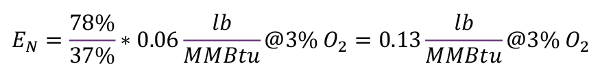 Although the regenerative burner system emits 0.08 lb/MMBtu (70 ppm) @ 3 percent O2, it stays well below the corrected limit (EN) of approximately 0.13 lb/MMBtu (105 ppm) @ 3 percent O2, thus saving 33 percent NOx emissions per year compared to the cold air burners.
Conclusion
There are a variety of burner types available with varying levels of complexity and efficiency.
Most high-efficiency gas burners preheat the combustion air to increase the combustion efficiency. Traditionally, there is a tradeoff between efficiency and NOx emissions; however, FLOX combustion makes it possible to have the best of both worlds.
Finally, if combustion efficiency is not considered when establishing a limitation for NOx emissions, this can lead to the selection of equipment which actually produces higher absolute emissions.
However, a very simple correction factor can be applied to adjust NOx emissions limitations to properly reflect combustion efficiency.
References
- Joachim G. Wünning, Ambrogio Milani: Handbook of Burner Technology for Industrial Furnaces, 2nd Edition, Vulkan Verlag, 2015
- Image provided by WS Wärmeprozesstechnik GmbH, Dornierstr. 14, 71272 Renningen, Germany
- Joachim G. Wünning: Flameless Oxidation, 6th HiTACG Symposium, Essen, Germany, 2005; flox.com/documents/05_HTACG_FLOX.pdf
- Uwe Götze, Deryl Northcott, Peter Schuster: Investment Appraisal – Methods and Models, Springer, 2010
About the authors
Steven R. Mickey is a graduate of Cornell University with a Bachelor of Science in Mechanical & Aerospace Engineering. He has been with WS Thermal Process Technology Inc. in Lorain, Ohio, for more than 17 years.
Martin G. Schönfelder is a co-owner of WS Thermal Process Technology Inc. He is based at the company’s headquarters in Renningen, Germany.
Joachim G. Wünning is a co-owner of WS Thermal Process Technology Inc. He is based at the company’s headquarters in Renningen, Germany.


 general practice for CQI-9 and AMS2750E")
 steels")


