


During an induction-hardening process, the part surface is heated using a medium- to high-frequency inductor. Once the desired depth of austenitization is reached, the part surface is quenched to transform the austenite to martensite. Compared to traditional furnace heating and liquid quenching, the induction process is much more energy efficient due to the rapid heating and formation of only a layer of austenite on the surface as opposed to austenitizing the entire volume of the part. The induction process also gives more options for process improvements with respect to case profile and residual stresses due to the large temperature gradient that exists between the surface and the core of the component. [1-3] Material volume expansion occurs with the transformation from austenite to martensite, and this induces compressive surface stresses. However, stress evolution during a hardening process is nonlinear and part geometry can play a significant role in the stresses formed.
Phase transformations also cause changes in the thermal and mechanical properties of the steel, the volume of the material, the internal stresses between different phases, and internal stresses within the same phase. Simulation of the heat-treating process is complex, requiring complex algorithms and accurate databases of thermal, mechanical, and metallurgical properties of all phases over a large range of temperatures. Several commercial codes are available for heat-treatment modeling, but DANTE was used for the following case study. DANTE is a multi-phase material model that links to the finite element packages ABAQUS or ANSYS. DANTE is used to predict the phases, dimensional change, and in-process and residual stresses in a steel component resulting from a heat-treatment process of a carburized or through-hardened component. [4-5] The diffusive and martensitic phase transformation modes resident in DANTE are described in general by Equations 1 and 2:


where Φd and Φm are the volume fractions of individual diffusive phases and martensite transformed from austenite, respectively; Φa is the volume fraction of austenite remaining to transform; νd and νm are the respective mobilities of transformation, and νd is a function of temperature and νm is a constant; α1 and β1 are material-related constants of diffusive transformation; and α2, β2, and ϕ are constants of martensitic transformation. For each individual metallurgical phase, one set of transformation kinetics parameters is required.
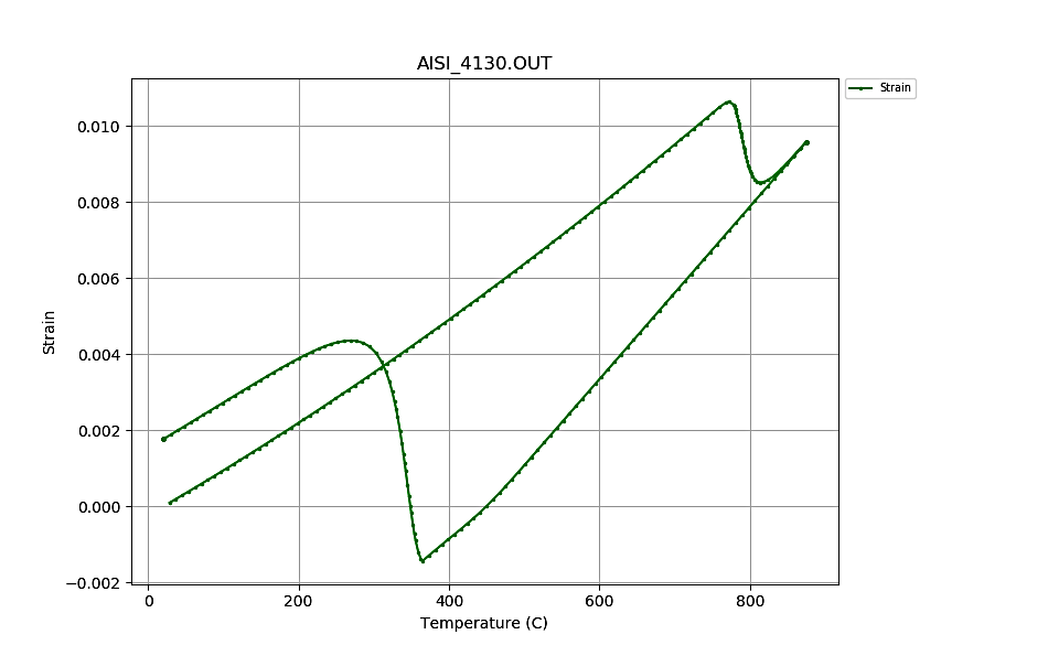
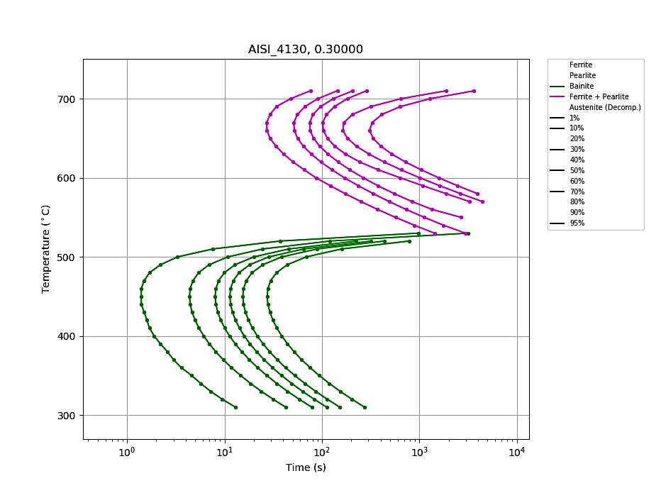
Figure 1 is a strain plot for a dilatometry sample generated from the DANTE material database for AISI 4130 (the steel alloy used for the case study); the horizontal axis is temperature, and the vertical axis is strain. Starting from room temperature, the sample is heated and cooled at a rate of 25°C/s, which is the approximate rates for the component in this case study. DANTE uses rate-based kinetics for both heating and cooling. Rate-based heating kinetics are important for induction hardening processes since the heating rates are generally far from an equilibrium condition. Figure 2 shows a time-temperature-transformation diagram for AISI 4130, using the nominal alloy chemistry generated from the DANTE material database. The DANTE software is also capable of modifying the hardenability of the steel based on slight modifications to the alloy chemistry. This case study used the nominal alloy chemistry for AISI 4130.
DANTE has a standard material database that includes all the necessary parameters needed to execute a heat-treatment simulation for many low- and medium-alloy steels. However, DANTE does not model the electromagnetic phenomenon of induction heating. Instead, DANTE can either map in the Joule heating history predicted by an electromagnetic software, or the Joule heating history can be determined from the component case depth. In this case, the Joule heating history was determined from the component case depth at critical locations.
Component, Process, and Model
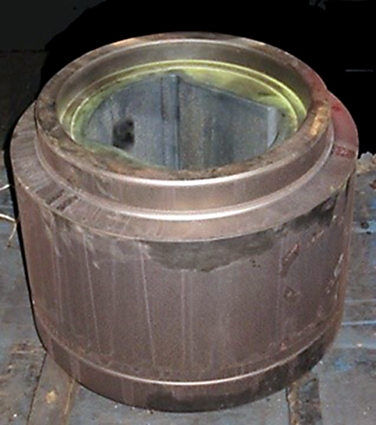
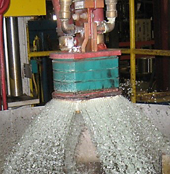
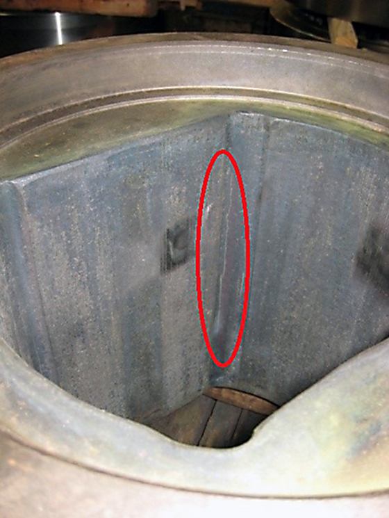
A large steel coupler made of AISI 4130, shown in Figure 3, was induction hardened using a scanning induction process. The component has a non-axisymmetric bore dimension of approximately 500 mm, an outer diameter of approximately 800 mm, and a height of approximately 500 mm. The inductor and quench head are shown in Figure 4. The inductor has a width of 50.8 mm and a travel speed of 1.27 mm/s. The spray exits the bottom of the inductor fixture and contacts the part 12.7 mm below the inductor, leading to a quench delay of 10 seconds. The coupler was experiencing cracking at a fillet in the bore of the component, as shown in Figure 5. The cracking mode suggested that high in-process circumferential stresses were responsible.
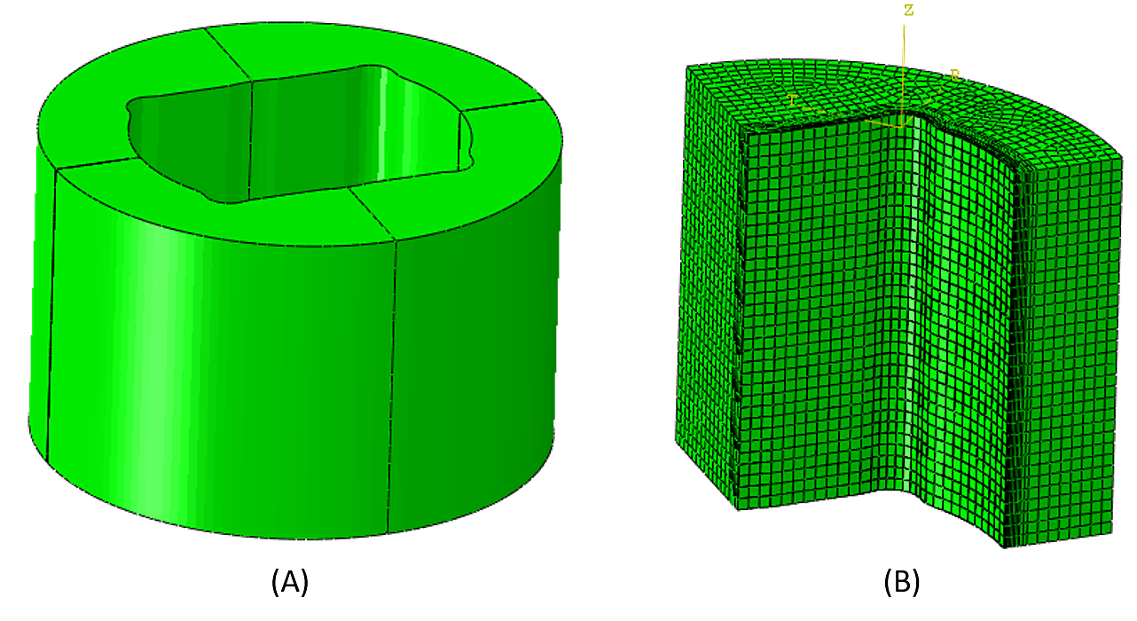
To determine the cause of cracking, a three-dimensional finite element analysis using the DANTE heat-treatment simulation software was conducted. The model was constructed and executed in ABAQUS Standard. Figure 6(A) shows the full CAD model, and Figure 6(B) shows the quarter-meshed model used for the finite element analysis. A quarter model can be used due to the symmetry of the part and because the heating and cooling conditions are assumed to act uniformly over all surfaces of the part in the circumferential direction. The quarter model consisted of 31,449 linear hexagonal elements and 34,680 nodes, with a higher mesh density near the bore surface to capture the high thermal and stress gradients present in an induction hardening process.
Discussion
The model predicted a high tensile hoop stress in the location where cracking was witnessed on the actual component. DANTE does not predict the propensity to crack. In this case, the predicted surface tensile stresses are high enough to cause surface cracking of as-quenched martensite in AISI 4130, especially if any surface defect is present. Figure 7 shows a plot of hoop stress as a function of depth from the bore surface at the location of cracking. The inset of Figure 7 shows the hoop stress as a contour plot over the entire component. The local coordinates for the hoop stress line plot are relative to the fillet in the bore. The local coordinates for the contour plot are relative to the outer diameter to represent subsurface stresses more accurately.
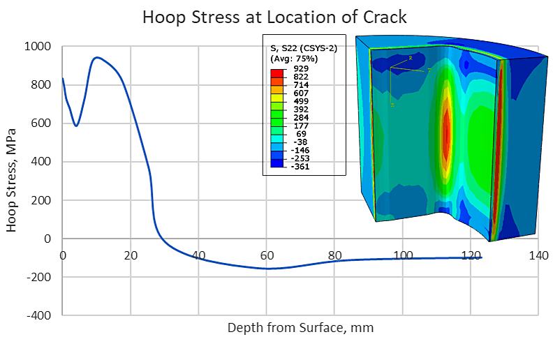
The high tensile stress under the bore surface is expected and is a consequence of the surface hardening process. Properly surface hardened parts should have a layer of surface compression, followed by a layer of tension. The subsurface tensile stresses are generally in response to the surface compression and are there to balance the compressive stresses. For this case, the induction hardening process resulted in substantial surface tension, even away from the problematic area. This can be quite common for induction hardened parts. As the martensite transformation front proceeds from the bore surface outward, it exerts an outward force on the freshly formed martensite. This behavior can reduce some of the compression created from the martensite volume expansion, even driving the bore surface into tension if the case is deep enough. For carburized components, the transformation starts subsurface in the lower carbon regions and progresses toward the regions of higher carbon. The carburized hardening behavior will always result in surface compressive stresses since the surface is the last volume of material to transform.
Figure 8 shows the time history of temperature and hoop stress at the location of cracking. There are several interesting aspects to this history. The following is a discussion in reference to the four points marked on the plot in Figure 8. Point 1 shows the instant the location begins to be heated by the inductor. Leading up to the time at Point 1, the surface goes into compression to balance the tensile stress generated from the heating of the material just below the location in question. Generally, heating the bore surface drives the surface into compression as the material tries to expand, but is unable to because it is constrained by the surrounding material. However, in this case, heating causes tension. This is due to non-axisymmetric geometry of the part and the fillet being spread open by the expanding material to either side of the fillet and stretching the material in the fillet region.
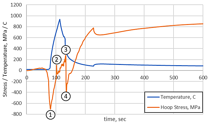
Point 2 in Figure 8 is the instant the material begins its transformation to austenite. Generally, the shrinkage associated with the transformation causes tensile stresses to be formed. However, in this case, the tension is relieved due to the bore surface shrinkage that allows the fillet to close and the tensile stress to decrease. Up to this point, the behavior related to stress formation has been the opposite of what is normally observed during a hardening process. This is all due to the unique geometry of the bore. By having flat, orthogonal surfaces in the bore and an outer axisymmetric shape, it creates unique stress concentrations in the fillet.
Point 3 in Figure 8 is the moment the surface point begins to transform to martensite. The surface is driven into compression due to the volume expansion of the martensite phase from the austenite phase. This behavior is common during a hardening process, since not even geometry can alter the high compression generated from the austenite-to-martensite transformation.
Point 4 is the end of the martensite transformation, but the bore surface of the part is still cooling. The cooling creates surface tension at the critical location due to the opening of the fillet as the flat surfaces to either side thermally contract. It is this final 200°C (320°F) of cooling that causes the component fillet to crack as the surface tensile stress exceeds 800 MPa (116 ksi). This is in excess of the tensile strength of AISI 4130 in the tempered condition and should also be in excess of the as-quenched tensile strength as well. If it is not in excess outright, any minor surface defect or inclusion will create stress concentrations in excess of the allowable tensile strength.
Process Improvement
With an understanding of the cause of the cracking, a solution could then be sought. The concern was that cooling after the martensite transformation was causing the cracking issues. The easiest way to rectify this type of behavior is to use preheating to raise the temperature of the entire component before induction hardening begins. This can be accomplished using sub-critical furnace heating or a low-frequency induction heating process. By doing so, the entire component will cool and shrink after hardening is complete, pulling the surface into compression.
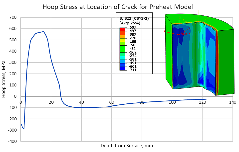
A single preheating temperature of 260°C (500°F) was modeled to show the feasibility of this concept. Figure 9 shows the residual hoop stress profile in terms of depth at the crack location, with the local coordinates relative to the fillet in the bore. The inset in Figure 9 is a contour plot of the hoop stress over the entire component with the local coordinates relative to the outer diameter. As can be seen, the residual stress is now in compression. However, the complete time history must be examined to ensure there was no cracking propensity prior to the component reaching room temperature. Figure 10 shows the hoop stress as a function of time for a point on the surface at the cracking location. A brief discussion with respect to the four points shown in Figure 10 follows.
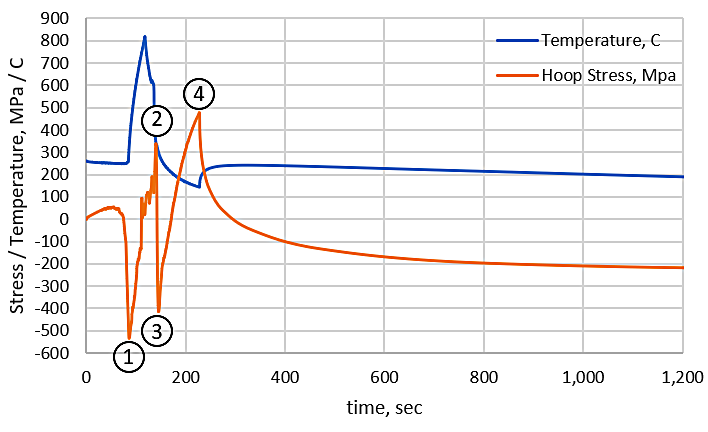
As with the non-preheated coupler, the first point goes against normal heating behavior as it is driven into tension by the induction heating process. The compression prior to Point 1 is in response to the material just below it going into tension from the heating process. Point 1 is the instant the area in question begins to be heated by the inductor. The transformation to austenite is not as pronounced as with the non-preheated sample, and Point 2 on Figure 10 shows the instant the martensite transformation begins on the surface at the location of cracking. Point 3 shows the end of the martensite transformation. As with the non-preheated coupler, the surface is pulled into tension as the material cools from the martensite finish temperature. However, upon reaching 200°C (500°F), the stresses begin to reverse as the entire component begins to cool from the preheat temperature. This cooling of the entire body pulls the entire surface into compression, not just the area associated with the cracking. While a preheat temperature of 200°C (500°F) effectively removed the tension on the surface of the component and appears to have reduced the propensity for cracking, the temperature is by no means optimized for this particular component. Further modeling could be used to determine the optimal preheat temperature for compressive residual stress, though the activity was not performed for this particular case. The customer was happy with the results provided by the 200°C (500°F) preheat.
In conclusion, heat-treatment simulation software such as DANTE can be a powerful tool in root cause failure analysis of induction hardened parts. By using DANTE, it was possible to determine the cause of cracking for a large, induction-hardened steel coupler. The cause of cracking was related to the cooling after the transformation to martensite was already complete. In order to resolve the cracking issue, a preheat prior to austenitization was modeled and shown to significantly reduce the in-process stresses and reverse the residual surface stress from tension to compression. Heat-treatment responses, especially from localized heat treatments such as induction hardening, are often difficult to predict due to the directional differences of thermal expansions, contractions, and phase transformations. A predictive software like DANTE offers a means of understanding the local thermal and stress histories that a component experiences, and the reasons that cracking may or may not be an issue. In this case, cracking was an issue for conventional induction hardening, but a process modification, exposed by modeling, was discovered to successfully harden the bore of this component.
References
- Induction Heating and Heat Treating, Vol 4C, ASM Handbook, V. Rudnev and G. Totten, eds., ASM Intl., 2014.
- Goldstein, R., Nemkov, V., Madeira, R.: Optimizing AxleScan Hardening Inductors. Industrial Heating, 12, 2007.
- Golovin, G., Residual Stresses and Deformation during High-Frequency Surface Hardening, Mashghiz, Moscow, 1962 (in Russian).
- Ferguson, B., Freborg, A., and Petrus, G., “Software Simulates Quenching”, Advanced Materials and Processes, H31-H36, August (2000).
- Dowling, W., et al., “Development of a Carburizing and Quenching Simulation Tool: Program Overview,” 2nd Int. Conference on Quenching and Control of Distortion, eds, G. Totten, et al., ASM Int., 1996.


 general practice for CQI-9 and AMS2750E")


