


This study investigated the interface morphology, microstructure composition, and connection strength of 7A52 aluminum alloy-Al2O3 ceramic brazed joints under heat-treatment conditions. Alumina ceramics were first treated with electroless nickel plating, followed by vacuum heat treatment at different temperatures. Then, an Al-Si-Mg intermediate layer was placed between the treated alumina ceramic and 7A52 aluminum alloy for brazing under the conditions of welding temperature 590, holding time 1 hour, pressure 2 MPa. Results showed that when heat treatment was performed at 350°C and below, the nickel-plated metal had an amorphous structure, and when performed at 400°C, the nickel-plated layer had a crystalline structure and the brittle phase Ni3P was precipitated. When the heat-treatment temperature was 350°C, the joint shear strength reached the maximum, which was 68.7 MPa.
Introduction
Aluminum alloy has been widely used in structural parts of airplanes, rockets, ships, and lightweight vehicles for its excellent mechanical properties and high-specific strength. Among them, 7A52 aluminum alloy has the advantages of high-specific strength, high-specific rigidity, and strong heat resistance, making it widely used in reducing weight for the automobile industry [Feng et al., 2016]. However, as society has developed, the number of vehicles on the road has grown rapidly, making the road safety situation increasingly complex. Therefore, as road vehicles, especially special vehicles, become more lightweight, it is necessary to improve the vehicle protection performance as much as possible.
Ceramics have high hardness, high compressive strength, and good elastic properties, but its brittleness limits the application. Combining it with aluminum alloy, which has high-specific strength and low density, high-performance lightweight composite materials can be manufactured, which can greatly reduce the weight of the auto bodies. However, in the manufacturing process of ceramic-metal composite materials, there exists a problem of reliable connection between metal aluminum alloy and alumina ceramic with different physical and chemical properties [Gama et al., 2001; Tasdemirci et al., 2012; Serjouei et al., 2017]. At present, there are more methods for metal sealing ceramic, each with its own advantages, disadvantages, and limitations. Currently, commonly used ballistic ceramics mainly include Al2O3, SiC, Si3N4, B4C, etc. Existing research results show the connection of aluminum and ceramic has a great influence on auto bodies’ performance.
At present, many methods of connecting alumina ceramic and aluminum have been developed, such as diffusion bonding, friction bonding, active casting, active surface crimping, electrostatic pressure bonding, ultrasonic welding, indirect brazing, etc. For example, Nicholas and Crispin realized the connection of aluminum and alumina ceramic in argon or vacuum with a pressure of 50 MPa and a connection time of 30 minutes [Nicholas and Crispin, 1982]. Fauzi et al. used the friction connection method to realize the connection between alumina ceramic and aluminum under the conditions of rotation speed 1,250–2,500 rpm, pressure 7 Mpa, and pressure time 20 seconds [Ahmad Fauzi et al., 2010]. Peng Rong et al. used the active casting method to manufacture Al-Al2O3 ceramic joint samples at 660-750°C and measured the tensile strength of the connection interface [Peng et al., 2002]. TWI enterprise manufactured composite products of alumina ceramic and aluminum made by ultrasonic welding.
Since the oxide film on the aluminum surface hinders the wetting of aluminum and ceramic, the interface residual stress is high. The joint strength of the above method is generally not high, and it is easy to cause cracking. In order to improve the wettability, relieve residual stress, increase the strength, and inhibit cracking, in addition to the pre-treatment of aluminum alloy before welding, indirect brazing can be used, such as plating Ni on the ceramic surface and then brazing with aluminum-based solder. Nickel-based amorphous materials prepared by electroless plating often show high catalytic activity in the field of catalysis. At the same time, it is often used in the preparation of anti-corrosion materials. The anti-corrosion film is plated on the metal surface without electricity to achieve the same effect as electroplating [Song et al., 2020]. Since the amorphous plating is a high-energy state and has internal stress, it still has a certain impact on the joint performance. After heat treatment of the plated parts, the internal stress in the plating relaxes as the microscopic defects of the crystal lattice are eliminated.
In this article, electroless nickel plating was performed on the alumina ceramic surface, and the nickel-plated ceramics were heat treated. An Al-Si-Mg intermediate layer was placed between the alumina ceramic and 7A52 aluminum alloy for brazing. The interface morphology, microstructure composition, and connection strength of 7A52 aluminum alloy-Al2O3 ceramic brazed joints under heat treatment conditions were investigated.
Materials and Methods
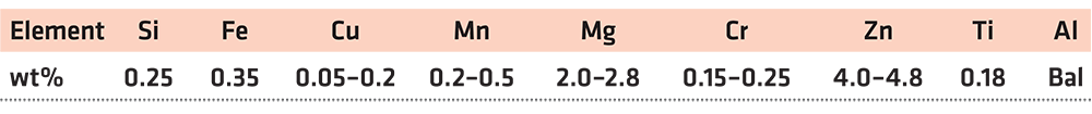
The aluminum alloy used for research was 7A52 aluminum alloy, which had been widely used as a composite armor material in engineering. The main chemical composition of the alloy is shown in Table 1. Before welding, it is necessary to remove impurities and oxide film on the aluminum alloy surface. First, degrease the surface with acetone solvent, then alkali wash with 10% NaOH solution at 50°C for 5 minutes, and then rinse with running water. After alkaline washing, acid wash with 30% HNO3 solution at 60°C for 2 minutes, then rinse with running water, and, finally, dry at low temperature.
The pressure brazing was carried out under the conditions of welding temperature 590°C, holding time 1 hour, pressure 2 MPa by vacuum hot pressing brazing furnace, and the vacuum degree of the vacuum furnace was 1.33 ↔ 10-3Pa. The Al2O3 ceramic ball used in the experiment, whose diameter was 10 mm, was treated with surface electroless Ni-P plating. The main process of electroless nickel plating in this article was: pretreatment → degreasing → coarsening → sensitization → activation → reduction → plating. The size of 7A52 aluminum alloy was 16 ↔ 16 ↔ 8 mm3, and the thickness of Al-Si-Mg solder was 0.1 mm. The three were assembled in order, and the assembly diagram was shown in Figure 1. Before the experiment, Al-Si-Mg filling material was cut into a square with 18 mm side length, and then washed with 15% hot sodium hydroxide solution (50°C) for 30-40 seconds, rinsed immediately with running water after the alkaline washing. Then it was washed with 10% nitric acid solution for 10-15 seconds, rinsed with running water shortly after washing and finally placed between the samples.

Results and Discussion
Evolution of Ceramic Surface Plating
The physical and chemical properties of Al2O3 ceramic and 7A52 aluminum alloy were different. In order to improve the poor wettability and low bonding strength of ceramic and metals, the method of electroless nickel plating was used to realize the metallization of ceramic surface. Studies showed the Ni-P plating crystalline structure obtained by electroless plating had three types. In general, when the phosphorus content in the plating was less than 3%, the plating structure was crystalline; when the phosphorus content was greater than 8%, the plating structure was amorphous; when the phosphorus content was 3% to 8%, the plating structure was the mixture of non-crystals and microcrystals. In this experiment, the phosphorus content in the plating was about 8.5% [Zou et al., 2004]. The amorphous plating was in a high-energy state and had internal stress; the internal stress would be relaxed to a certain extent after plating heat treatment. If the heat-treatment temperature was higher than the crystallization temperature, the amorphous structure would first be transformed into crystallites, and then the crystallites would further grow into grains [Li et al., 2015]. In addition, high-vacuum heat-treatment process can also release the hydrogen adsorbed in the plating during electroless plating to a certain extent. Therefore, when the vacuum heat-treatment temperature was low, as the heat-treatment temperature rose, the bonding strength between the plating and the substrate increased. However, when the heat-treatment temperature rose further, on the one hand, the grains would be further coarsened, and brittle phases such as Ni3P would be precipitated on the Ni-P plating. On the other hand, due to the difference in the athermal expansion coefficient between the substrate and the plating, a new residual stress would be formed while the internal stress generated by the state tissue relaxed in the amorphous. Therefore, if the heat-treatment temperature was too high, it would lead to the plating cohesion, and the bonding strength of plating and substrate decrease [Zhang et al., 2004].
When performing vacuum heat treatment on nickel-plated ceramic, the vacuum degree was 5 ↔ 10-3 Pa, the holding time was 1 hour, and the heat-treatment temperature was 200, 250, 300, 350, and 400°C. Figure 2 shows the X-ray diffraction analysis results of the nickel-plated layer on the ceramic surface after vacuum heat treatment.
In Figure 2, when the temperature was below 350°C, the diffraction peaks of Ni and P related crystalline structure were not seen in the plating. When the temperature was kept at 400°C for 1 hour, the diffraction peaks of Ni and Ni3P appeared, indicating that a certain amount of crystalline structure appeared at this time. Ni3P and other crystalline structures were brittle phases, which was not conducive to improving the welded joint strength of aluminum alloy and ceramic.
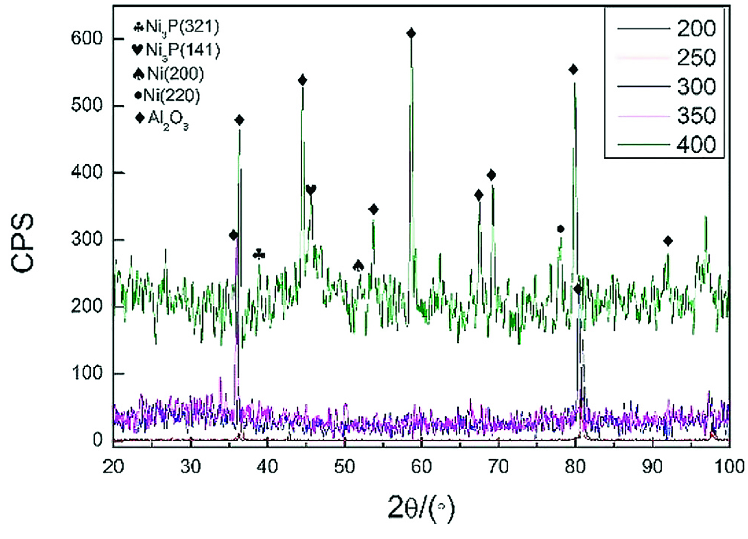
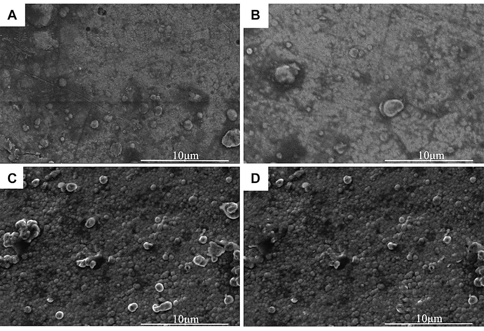
Figure 3 showed the micromorphology of the nickel-plated layers on the Al2O3 surface after heat treatment at different temperatures. In Figure 3, after vacuum heat treatment, bubble-like spherical clusters were generated on the nickel-plated layer surface, and the diameter of the spherical clusters was about 1-2 μm. As shown in Figure 3A, when the heat-treatment temperature was 200°C, there were only a few clusters on the plating surface. And as shown in Figure 3B, C, D, with the increase of the vacuum heat-treatment temperature, the spherical clusters grew in number and became denser. This was because hydrogen was generated during the electroless nickel plating process. The hydrogen existed inside the plating. At the same time, there are defects and internal stress in the plating. When the heat-treatment temperature was 200°C, the residual hydrogen in the plating escaped, eliminating the defects and internal stress. Due to the low heat-treatment temperature at this time, little hydrogen was released, so there were not many clusters on the plating surface. However, as the heat-treatment temperature rose, more hydrogen inside the plating escaped, so the spherical clusters on the surface of the plating became denser. At the same time, the defects and internal stress of the plating were eliminated more fully.
The Interface of 7A52 Aluminum Alloy-Al2O3 Ceramic Hot-Press Diffusion Brazing Joints
In order to effectively improve the bonding performance of 7A52 aluminum alloy and Al2O3 (Ni) ceramic, improve the connection process between the two, and increase the joint strength, after vacuum heat treatment of the nickel-plated Al2O3 ceramic, the Al-Si-Mg intermediate layer was subjected to hot press diffusion to realize the welding of the two. Figure 4 shows the micromorphology of Al2O3(Ni) ceramic-aluminum alloy joints at different heat treatment temperatures when the process conditions were 590°C, 2 MPa, and 1 hour.
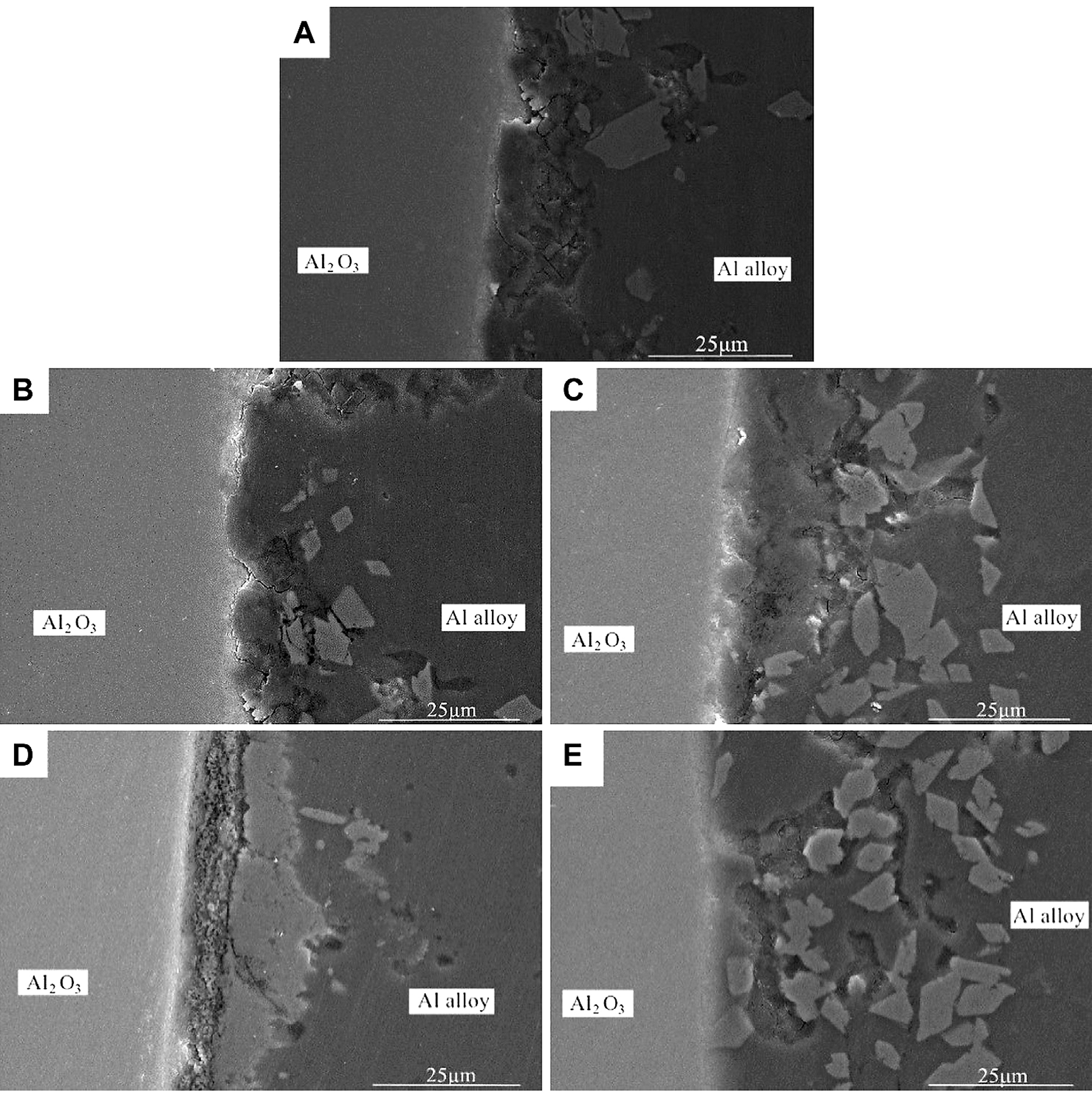
It can be seen from Figure 4 that, after vacuum heat treatment, there were no gaps, cracks, holes, or other defects at the interface between the nickel-plated metal layer and the Al2O3 ceramic. Compared with the interface without heat treatment, it had a tighter combination and a more natural transition. As shown in Figure 4A-E, with the rise of the heat-treatment temperature, the interface became more natural and the combination became tighter. When the heat treatment increased to 400°C, there was no interface between the nickel-plated metal layer and the aluminum alloy. This is because that, after vacuum heat treatment, the internal defects and internal stress of the nickel-plated layer were eliminated, and as the heat treatment temperature rose, the layer structure became denser. Besides, during the welding process, the solid Ni continually diffused into the Al-Si-Mg and reacted with Al to form an Al-Ni intermetallic compound. It can also be seen from Figure 4 that many irregular blocky substances were scattered at the interface between the intermediate layer and the aluminum alloy. It was speculated that they were formed by the crushing of the nickel-plated layer under pressure, and their composition was an Al-Ni intermetallic compound.
The above micromorphology analysis revealed the 7A52 aluminum alloy was tightly combined with the vacuum heat-treated Al2O3 (Ni) ceramic, the joints had natural transition,s and no defect. In order to explore the distribution status and changing trend of interface elements, EDS was used to scan the joints by line scan and point scan. Figure 5 show the EDS scanning analysis spectra of the joints’ elements under different heat-treatment temperatures. It can be seen from Figure 4 that the micromorphology of the nickel plating on the ceramic surface under 200°C heat treatment was relatively similar to it under 250°C, and that under 300°C was similar to 350°C, so it just analyzed the line scan of the joints under 250, 300, and 400°C.
In Figure 5A, the Al element content was the highest. From the scan line starting point to 10 μm, the Al element content increased greatly, and the Mg element also increased, while the Ni element with low content changed little. Therefore, this range was the Al-Si-Mg solder zone. At the scan line 10-12 µm, the Al element content decreased relatively, while the Ni element content showed an increasing trend, so this range was the junction of the solder and the nickel-plated metal layer. At the scan line 12-16 µm, the element contents of Al and Ni were relatively high at the same time. In this range, the nickel-plated layer reacted with the Al element, which generated many Al-Ni intermetallic compounds, making the element contents of Al and Ni high. Thus, this range was the Al-Ni intermetallic compounds zone. At the scan line 16-18 µm, the element contents of Al and Ni decreased, but the Si element content increased sharply. This was due to the formation of an Al-Si eutectic phase. At the scan line 18-24 μm, the elements change similarly to that at 12-16 μm, which would not be repeated here. At the scan line 24-27 μm, Al, Si, and Mg elements all showed an increasing trend, and, at the same time, the Ni element content decreased to the lowest. This range was considered to be the Al-Si-Mg solder zone. It is worth noting that the Zr element content gradually decreased from the scan line starting point to 10 µm, and then the content had been stable at a very low level. In this experiment, only the 7A52 aluminum alloy contained Zr, thus it can be known that the active element Zr in the aluminum alloy diffused, gathered on the Al2O3 ceramic surface and reacted with it.

In Figure 5B, the element contents of Al, Si, and Mg were all at a relatively high level at the scan line 4-14 μm and 20-28 μm. Therefore, it can be seen that this range was the solder zone. At scan line 14-20 μm, the Al element content was the highest, and the other elements’ contents were at the lowest level. It was considered that Si and Mg in this range diffused to both sides, thus forming peaks of Mg and Si on both sides. Now that Mg and Si had the lowest element contents here, Al had the highest. In addition, the Zr element was similar to that shown in Figure 5A, which gathered on the Al2O3 ceramic surface.
In Figure 5C, at the scan line 10-20 µm, the element contents of Si and Mg were at relatively high levels, and the Al element content was relatively low. It was considered that this range was the solder zone. The Mg element in the solder gathered here, making the Mg element content the highest. At the scan line 20-25 μm, the Al element content was high, and the Ni element content was the highest. According to the previous analysis, it can be seen that there were many Al-Ni intermetallic compounds in this range.
From Al2O3 ceramic to aluminum alloy, according to the above analysis, the following zones existed at the joint interface: Zr-ceramic reaction zone, solder zone, Al-Ni intermetallic compound zone, and Al-Si eutectic zone. In addition, the solder zone, Al-Ni intermetallic compound zone, and Al-Si eutectic zone were intertwined.
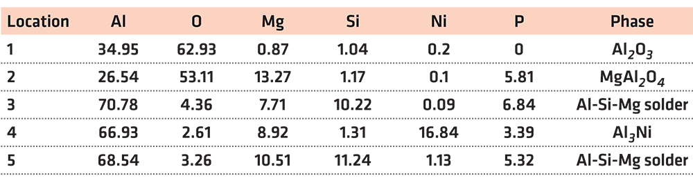
In order to accurately analyze the elemental composition at the interface between the vacuum heat-treated Al2O3(Ni) ceramic and the 7A52 aluminum alloy, an EDS point scan was performed. Figure 6 shows the selected points at the interface of the joint under 250°C heat treatment. Table 2 show the corresponding composition of each point in Figure 6. Figure 7 shows the selected points at the interface of the joint under 300°C heat treatment. Table 3 shows the corresponding components at each point in Figure 7.
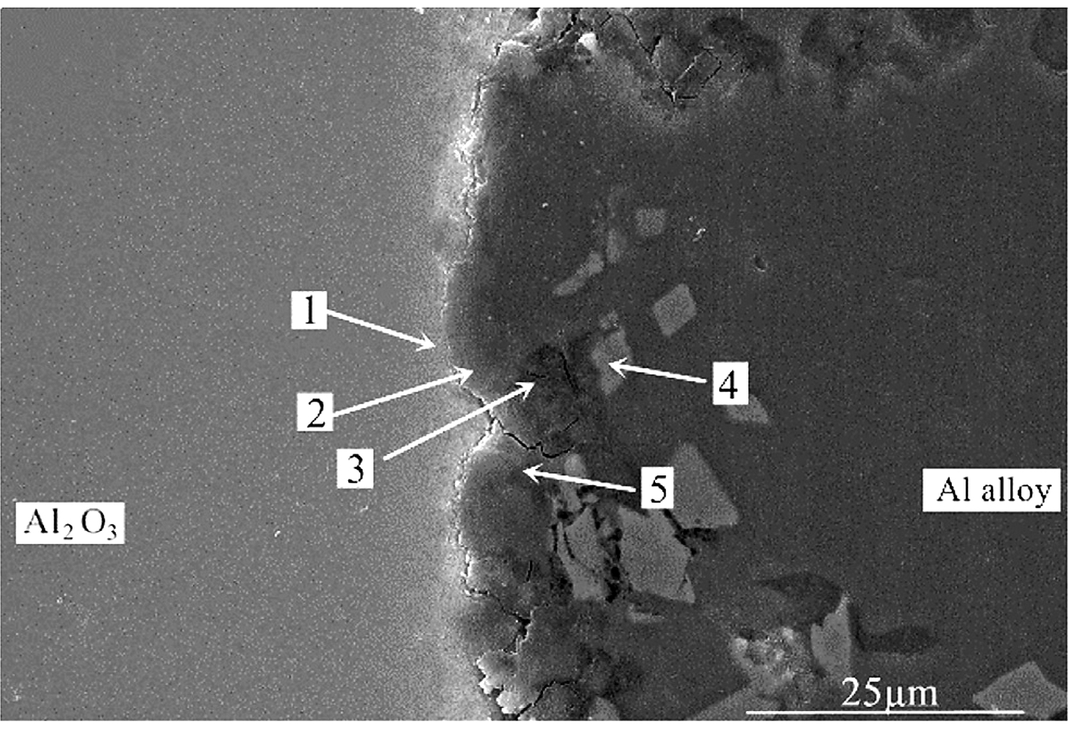
In Table 2, at position 1, the main composition was Al2O3, and the Mg and Si elements diffused to there. At position 2, the main component was spinel. It was considered that the liquid phase was generated after the solder reached the eutectic temperature, then the active element Mg in the solder diffused and gathered to this point and reacted with the Al2O3 ceramic. The reaction product was spinel, an enhanced phase in the interface. At position 3, it was the Al-Si-Mg filling material zone, where the Al element content was high. At position 4, the main composition was Al3Ni intermetallic compound, which was the result of the interaction between the filling material and the nickel-plated layer. Position 5 was the same as position 3, which was the Al-Si-Mg solder zone. According to the above analysis, the structures at the joint interface were: Al2O3 ceramic/spinel (MgAl2O4)/Al-Si-Mg brazing filler metal zone/Al3Ni/7A52 aluminum alloy.
In Table 3, the Zr element appears at position 1. In this experiment, only the 7A52 aluminum alloy contained Zr. Zr was an active element and had a high affinity for O element. The Zr element diffused from the aluminum alloy and gathered at position 1, and then reacted with O element to generate ZrO2. Since the Zr element content in 7A52 aluminum alloy was only 0.05-0.15%, it was certain that ZrO2 generated at the interface was very small. There was also Al2O3 in position 1. ZrO2 also appeared at position 2, and the active element Mg in the solder reacted with the Al2O3 ceramic to generate a spinel (MgAl2O4) reinforcing phase. Positions 3, 4, and 5 were located outside of the reaction zone of the solder and ceramic (the spinel generation zone), so here was the brazing filler metal zone. At position 6, the Al3Ni intermetallic compound was inferred to be generated based on the atomic percentage, which corroborated the previous analysis. The filling material reacted with solid Ni, continuously dissolving the nickel-plated metal layer; meanwhile, a certain pressure was applied during the welding process. Under the combined action of the two, the morphology of the nickel-plated layer became fragmented, and Al-Ni intermetallic compounds were formed in the layer. Therefore, under this process condition, the interface structures of the joint were: Al2O3 ceramic/ZrO2 (trace amount)/spinel (MgAl2O4)/Al-Si-Mg brazing filler metal zone/Al3Ni/7A52 aluminum alloy.

After 400°C heat treatment, the interface structure of Al2O3(Ni) ceramic-7A52 aluminum alloy joint was the same as that of 300°C.
Strength Analysis of 7A52 Aluminum Alloy-Al2O3 Ceramic Hot-Press Diffusion Brazing Joints
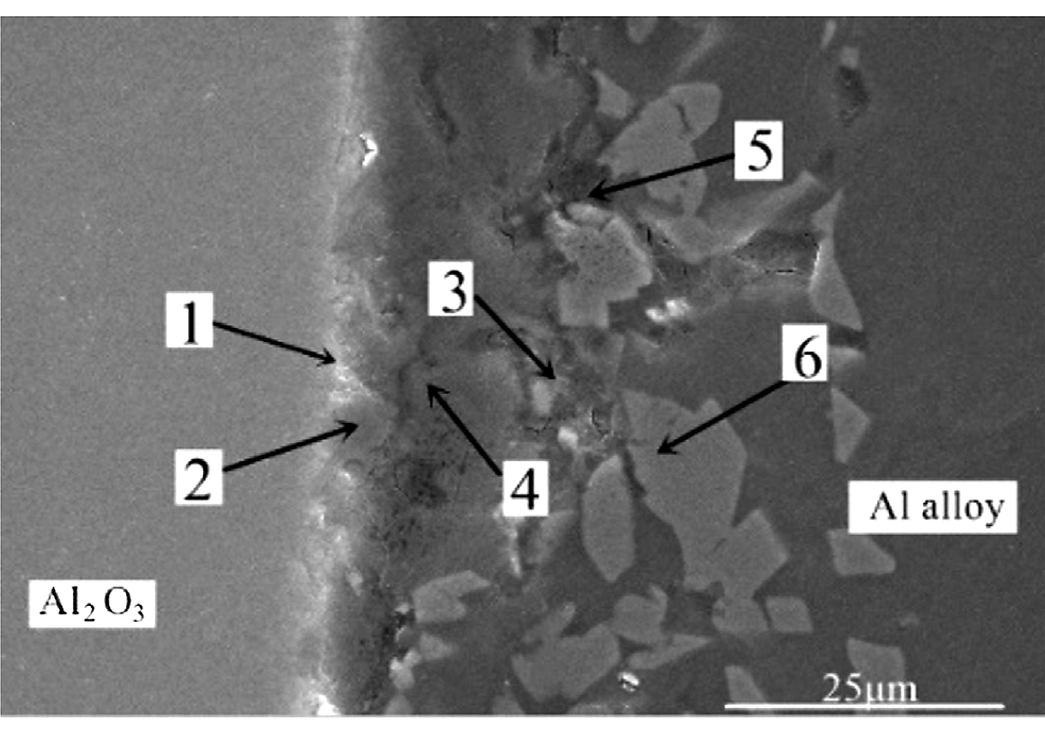
Figure 8 shows the shear strength of 7A52 aluminum alloy-Al2O3(Ni) ceramic pressure brazed joints under the conditions of welding temperature 590°C, holding time 1 hour, pressure 2 MPa, and different heat-treatment temperatures. It can be seen from Figure 8 that the joint had the lowest strength, 38 MPa, when the vacuum heat-treatment temperature was 200°C. Without heat treatment, under the same welding process conditions, the joint strength was 19.8 MPa. Therefore, the heat-treatment process had a significant effect on the improvement of joint strength. It was analyzed that, due to the electroless plating implemented in this experiment, the P element content w(P) on the surface of the Ni-P metal layer was 8.5%, so the plating metal was amorphous. The amorphous plating was in a high-energy state and had internal stress; the internal stress would be relaxed to a certain extent after plating heat treatment. And the H element adsorbed in the plating during the plating process could be released to a certain extent. Therefore, the bonding strength of the plating and the ceramic would be somewhat improved, the “locking” effect became stronger, and the combination became tighter, which had a significant effect on improving the strength of the brazed joints. Besides, as the vacuum heat-treatment temperature increased, the joint strength gradually increased. When the temperature rose to 350°C, the joint strength reached the maximum, which was 68.7 MPa. This was because the higher the heat-treatment temperature, the better the relaxation of internal stress and the release of H elements in the plating. Thus, the bonding strength between the plating and the substrate gradually increased, and then the strength of the brazed joint also gradually increased. However, when the heat-treatment temperature increased from 350 to 400°C, the joint strength decreased from 68.7 to 50.18 MPa, decreased by 27%. It was analyzed that 400°C was higher than the crystallization temperature of the nickel-plated layer. The nickel-plated layer first transformed from an amorphous structure to microcrystalline, and then the microcrystals grew further. There was a difference in the thermal-expansion coefficient between the nickel-plated layer and the Al2O3 ceramic. Excessive heat-treatment temperature imposed the nickel-plated layer to generate new residual stress, which made the bonding effect of the layer and the Al2O3 ceramic matrix worse. Therefore, the strength of the brazed joint decreased. Meanwhile, according to the X-ray diffraction results, Ni3P(321) and Ni3P(141) were precipitated on the surface of the nickel-plated layer when the heat-treatment temperature was 400°C. The two precipitated substances were both brittle phases, making the nickel-plated layer more vulnerable to crushing under pressure and then decreasing the bonding strength of the layer and the Al2O3 ceramic matrix, which was also the reason for the decrease of brazed joint strength.
Figure 9 shows the macromorphology of the 7A52 aluminum alloy-Al2O3 ceramic joint fractures under the conditions of heat-treatment temperature 200°C, welding temperature 590°C, holding time 1 hour, and pressure 2 MPa. It can be seen from Figure 9A, B that the white substance was Al2O3 ceramic, the gray substance was the solder layer. The fracture occurred partly in the ceramic and partly in the solder layer. A layer of white substance was scattered on the surface of the solder layer, and it should be ceramic.
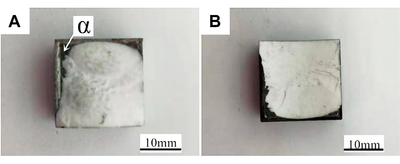
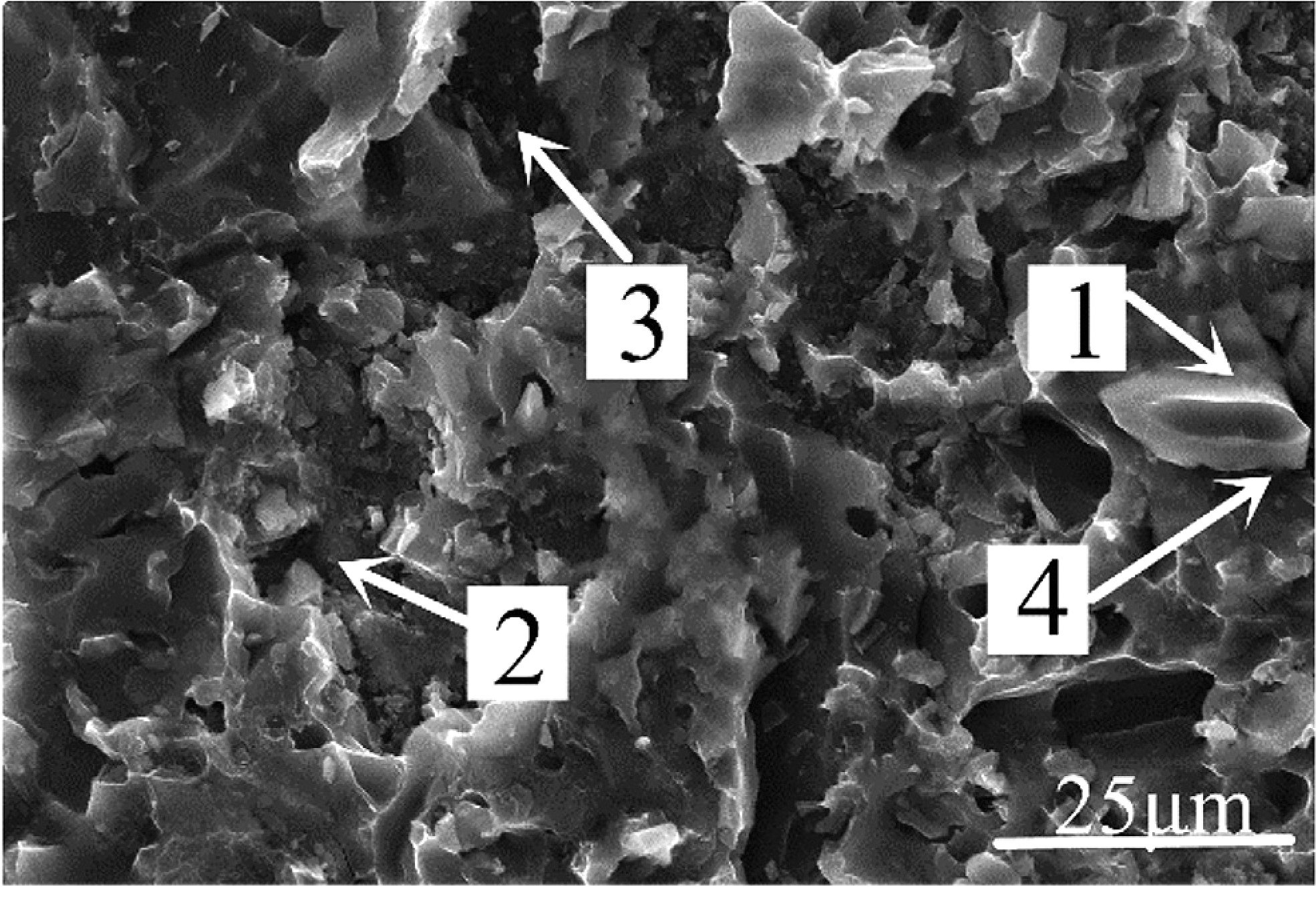
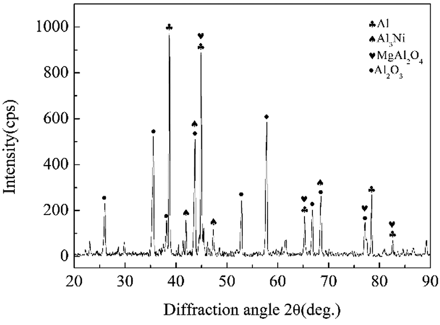
Figure 10 was the micromorphology of the α zone in Figure 9. From the fracture morphology, it can be concluded the fracture was brittle fracture. Table 4 shows the EDS scan results of four points in Figures 10, 11 showed the XRD diffraction result of the fracture in Figure 10. At position 1, the main composition was Al2O3, which was consistent with the previous analysis that the α area was a solder zone but was scattered with ceramic. At position 2, the main composition was Al-Si-Mg solder. At position 3, the main composition was Al3Ni intermetallic compound. The Al element in the filling material reacted with Ni, which continuously dissolved the nickel-plated layer. And then under the action of pressure, the nickel-plated layer partly broke and scattered in the liquid solder. Position 4 was near position 1, and its main composition was spinel (MgAl2O4), which meant the active element Mg in the brazing filler metal diffused to the surface of Al2O3 ceramic, where it gathered and reacted with the ceramic to form spinel.

Conclusion
1. Vacuum heat treatment was carried out for nickel-plated Al2O3 ceramics. When the heat treatment temperature was below 300°C, there were few cellular bumps on the surface of the nickel-plated layer, but when above 300°C, there were many cellular bumps on the surface of the nickel-plated layer. According to the results of XRD diffraction analysis, when heat treatment was performed at 350°C and below, the nickel-plated metal had an amorphous structure, and when performed at 400°C, the nickel-plated layer had a crystalline structure, and the brittle phase Ni3P was precipitated.
2. From Al2O3 ceramic to aluminum alloy, the following zones existed at the joint interface: Zr-ceramic reaction zone, brazing filler metal zone, Al-Ni intermetallic compound zone, and Al-Si eutectic zone. Besides, the brazing filler metal zone, Al-Ni intermetallic compound zone, and Al-Si eutectic zone were intertwined. The interface structures of the joint were: Al2O3 ceramic/ZrO2 (minor amount)/spinel (MgAl2O4)/Al-Si-Mg solder zone/Al3Ni/7A52 aluminum alloy.
3. Pressure brazing of 7A52 aluminum alloy-Al2O3(Ni) ceramic was carried out by Al-Si-MG brazing filler metal. It was found that the temperature of vacuum heat treatment was an important factor affecting the mechanical properties of the joint. The pressure brazing was carried out under the conditions of welding temperature 590°C, holding time 1 hour, pressure 2 MPa. When the heat-treatment temperature was 350°C and below, the joint strength increased with the increase of the heat-treatment temperature. When the temperature was 350°C, the joint shear strength reached the maximum, which was 68.7 MPa, but as the heat-treatment temperature increased to 400°C, the joint strength decreased by 27%-50.18 MPa.
Data Availability Statement
The original contributions presented in the study are included in the article/supplementary material. Further inquiries can be directed to the corresponding author.
Author Contributions
DZ: conceptualization and funding acquisition. XQ: methodology, visualization, formal analysis, and writing-original draft. XL: writing-review and editing. KW: resources, validation, project administration and supervision.
Funding
This work is supported by the China Postdoctoral Science Foundation (2020M682928) and the Stable Supporting Fund of Science and Technology (WDZC2020JJ021).
Conflict of Interest
The authors declare that the research was conducted in the absence of any commercial or financial relationships that could be construed as a potential conflict of interest.
References
- Ahmad Fauzi, M. N., Uday, M. B., Zuhailawati, H., and Ismail, A. B. (2010). Microstructure and mechanical properties of alumina-6061 aluminum alloy joined by friction welding. Mater. Des. 31, 670–676. doi:10.1016/j.matdes.2009.08.019.
- Feng, Y., Chen, J., Qiang, W., and Wang, K. (2016). Microstructure and mechanical properties of aluminium alloy 7A52 thick plates welded by robotic double-sided coaxial GTAW process. Mater. Sci. Eng. A. 673, 8–15. doi:10.1016/j.msea.2016.07.011.
- Gama, B. A., Bogetti, T. A., Fink, B. K., Yu, C.-J., Claar, T. D., Eifert, H. H., et al. (2001). Aluminum foam integral armor: a new dimension in armor design. Compos. Struct. 52 (3), 381–395. doi:10.1016/S0263-8223(01)00029-0.
- Li, T.-J., Li, G.-Q., and Wang, Y.-B. (2015). Residual stress tests of welded Q690 high-strength steel box- and H-sections. J. Constructional Steel Res. 115, 283–289. doi:10.1016/j.jcsr.2015.08.040.
- Nicholas, M. G., and Crispin, R. M. (1982). Diffusion bonding stainless steel to alumina using aluminium interlayers. J. Mater. Sci. 17, 3347–3360. doi:10.1007/BF01203505.
- Peng, R., Zhou, H., Ning, X.-S., Xu, W., and Lin, Y.-B. (2002). Research of performance of Al/Al2O3 substrate. J. Inorg. Mater. 17 (4), 731–736. doi:10.3321/j.issn:1000-324X.2002.04.015.
- Serjouei, A., Goura, G., Zhang, X., Idapalapati, S., and Tan, G. E. B. (2017). On improving ballistic limit of bi-layer ceramic-metal armor. Int. J. Impact Eng. 105, 54–67. doi:10.1016/j.ijimpeng.2016.09.015.
- Song, S., Wang, Y., Jiang, L., Zheng, Y., Chen, Y., and Chen, T. (2020). Progress in electroless plating preparation and applications of Nickel-based amorphous alloys. Mater. Sci. Technol. 28 (1), 81–90. doi:10.11951/j.issn.1005-0299.20180237.
- Tasdemirci, A., Tunusoglu, G., and Güden, M. 2012). The effect of the interlayer on the ballistic performance of ceramic/composite armors: experimental and numerical study. Int. J. Impact Eng. 44, 1–9. doi:10.1016/j.ijimpeng.2011.12.005.
- Zhang, J.-X., Guan, X.-J., and Sun, S. (2004). A modified Monte Carlo method in grain growth simulation. Acta Metallurgica Sinica 40 (5), 457–461. doi:10.3321/j.issn:0412-1961.2004.05.003.
- Zou, G., Aiping, W., Zhang, D., Meng, F., Bal, H., Zhang, Y., et al. (2004). Joint strengthwith soldering of Al2O3 ceramic after Ni-P chemical plating. Tsinghua Sci. Technol. 9 (5), 607–611. CNKI:SUN:QHDY.0.2004-05-00K.
Copyright © 2021 Deku Zhang, Xusheng Qian, Xiaopeng Li and Kehong Wang. (https://doi.org/10.3389/fmats.2021.634658) This is an open access article under the CC BY license (http://creativecommons.org/licenses/by/4.0/). It has been edited to conform to the style of Thermal Processing magazine.


 general practice for CQI-9 and AMS2750E")


