


This paper describes an approach for measuring material plasticity using contactless electromagnetic acoustic method. Harmonic generation from noncumulative fundamental longitudinal wave in specimen is studied based on numerical method, and the contribution to harmonic generation from tensile damage is shown to be higher than that from a geometric factor; more serious damages increase the amplitude of second harmonics. These two experimental setups (nonlinear piezoelectric method and nonlinear electromagnetic acoustic method) are used to assess the relative nonlinearity parameters of tensile damage of five aluminum alloy specimens along the thickness direction, and the proposed technique is as effective with the traditional nonlinear piezoelectric method. This result demonstrates that the ultrasonic nonlinear parameter can represent tensile damage with ultrasonic nonlinear parameter by noncontact electromagnetic acoustic method.
1. Introduction
The application of ultrasonic waves in engineering structure now is a critically significant method in nondestructive testing (NDT) and structural health monitoring (SHM). With the latest developments in image processing and mathematical and computer modeling, more sensitive and economical ways of looking at materials and structures have become possible when compared to the other inspection techniques [1]. The traditional ultrasonic testing method is based on the linear theory and depends on measuring particular parameters, including the size, the orientation, the location of crack, the acoustic velocity, the attenuation, and the transmission and reflection of ultrasonic wave to detect damage [2]. However, traditional linear ultrasonic methods detect cracks or features based on the order of the wavelength of the ultrasonic wave. They are sensitive to microstructural features that are orders of magnitude bigger than the wavelength, but linear ultrasonic testing is not sensitive to early-stage degradation and microcrack of materials without diffraction and attenuation effect. Therefore, the detection of early damage becomes an issue and advanced ultrasonic testing becomes strongly needed. In addition, the development of the ultrasonic testing method is a challenging task that should have several crucial applicative functions such as online evaluation, condition-based maintenance, fitness determination for service and remaining useful time, less cost and labor, required baseline, and required environmental data compensation methods. The nonlinear ultrasonic method has a powerful ability to characterize microstructural features in materials. The basic physical mechanism of higher harmonic generation, subharmonic generation, shift of resonance frequency, and mixed frequency response are introduced with applications to evaluation of microdamage. These effects are quantified with the measured acoustic nonlinearity parameter (ANP), which is caused by the interaction of a sinusoidal wave and microstructural features such as microcracks, precipitates, creep, fatigue, and plasticity [3–8] (i.e., features at the micron scale and below), and the ANP is a powerful indicator of the material state.
Currently, a number of investigators have applied nonlinear ultrasonic techniques to assess the damage in different metallic alloys such as early fatigue damage in Ti-6Al-4V specimens [9], heat-treated Cr-Mo-V steel [10], hardening in ASTM A710 steel [11], nickel-based superalloy samples under monotonic and fatigue loading [12], and plastic deformation in AL 1100-H16 alloy [13]. It is noted that the ANP, which is based on the fundamental and second harmonics, significantly changes with the damage.
The most commonly used nonlinear wave technique uses through-transmission bulk waves, which is applied in the field since access to both sides of the specimen is required. Longitudinal waves have the advantage, as compared to shear waves [14], of transferring energy to second harmonics; shear waves transfer energy to third harmonics. Therefore, it is more possible for nonlinear longitudinal wave to assess the material inner damage. In addition, nonlinear Rayleigh surface and Lamb waves are widely used to represent the material superficial or integral damage, which, with a smaller diffraction and attenuation, effects with long distance traveling.
However, most nonlinear ultrasonic applications detect material characterization and the existence of minute defects by piezoelectric ultrasonic method and a high nonlinear efficiency of a liquid coupling medium. The piezoelectric ultrasonic method is not appropriate for testing in extreme conditions and rough testing surfaces, and coupling medium affects the scan efficiency of the specimen to be measured. Therefore, noncontact ultrasonic testing method has a better application prospect. Sebastian et al. present noncontact an air-coupled ultrasonic technique for a nonlinear Rayleigh surface wave measurement of the relative nonlinearity parameters of two aluminum alloy specimens AL2024-T351 and AL 7075-T651 [15], but the ultrasonic conversion efficiency is not enough with the acoustic impedance mismatch. A study of Liu et al. makes use of the nonlinear laser ultrasonic method to perform fatigue crack measurements [16]. However, the laser ultrasonic method suffers from variations in optical reflectivity and is only feasible for specimens with highly reflective surfaces.
An electromagnetic acoustic transducer (EMAT) is a kind of sensor that can excite and receive ultrasonic waves without coupling agent. The EMAT can be designed to generate and measure the desired mode of elastic waves on the basis of the contactless coupling mechanisms. Various propagation modes can then be used to meet a wide range of measurement needs, like the SH mode only being available with the EMAT technique; this is one of the advantages over the air-coupled ultrasonic technique and laser ultrasonic technique [17, 18]. The axial shear wave on cylindrical Cr-Mo-V specimens was found to be capable of fatigue and creep deformation of the nonlinearity measurement under the magnetostriction-type EMAT exciting [19, 20]. Cobb et al. present an approach of acoustic nonlinearity of fatigue damage accumulation that uses Rayleigh waves generated from EMAT and electromagnetic acoustic resonance [21, 22]. With the optimization of a pulse current generator [23, 24], EMAT has succeeded to excite vibration amplitude in the material high enough to induct higher harmonics, and the EMAT has the potential study in the nonlinearity measurement to isolate materials’ nonlinearity. The objective of the current study is to explore the feasibility of a noncontact, electromagnetic acoustic technique to assess the acoustic nonlinearity parameter using nonlinear longitudinal waves. Section 2 presents nonlinear mechanics preliminaries based on the Murnaghan model. Section 3 presents the nonlinear characteristic obtained from numerical simulations. The two nonlinear ultrasonic methods are compared and analyzed in Section 4 and Section 5, respectively. Finally, conclusions are drawn in Section 6.
2. Principle
The principle of the electromagnetic-acoustic coupling process is the elastic response to periodic surface stresses that arise from Lorentz forces. An alternating current with the driving frequency (f > 20 kHz) is applied to the spiral coil of the electromagnetic acoustic transducers. The dynamic magnetic field beneath the meander coil will be induced by the alternating current (within the electromagnetic skin depth). Generally, both the static magnetic field and the dynamic magnetic field will contribute to the Lorentz force occurring in skin depth. Generally, the skin depth is far less than the acoustic wavelength. Thus, the Lorentz force occurring within the skin depth can approximately be regarded as a shear stress exerted on the surface of the specimen, and the surficial stress can be regarded as an excitation source for the generation of a series of ultrasonic modes. In other words, the acoustic fields (the mechanical displacement) are generated by the Lorentz surface stress.
We consider nonlinear ultrasonic technique where the received signal is not at the frequency of the exciting current, and metallic material is treated as weakly nonlinear elastic because the amplitude of the signal received at higher harmonics is very small relative to the excitation, then harmonics can be generated notably at twice the excitation frequency.
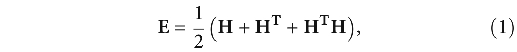
The Lagrangian formulation from continuum mechanics is exploited using the Green-Lagrange strain tensor E along with the first Piola-Kirchhoff stress tensor T1 and second Piola-Kirchhoff stress tensor T2. E is related to the displacement vector u, for simplicity, and the gradient of the displacement vector H. And the following relations exist between the above quantities [25, 26].
 where the linear strain is El, which is related to the action of linear ultrasonic.
 Comparing Equation 1 with Equation 2, the existence of the second-order term HTH is the main reason of nonlinear stress-strain, which includes geometric nonlinearity and material nonlinearity.
The stress-strain relation of higher harmonic generation for a hyper-elastic material is obtained from the nonlinear governing equations of Murnaghan model, which has a qualitative description of an harmonic vibration, and the strain energy function W(E) is
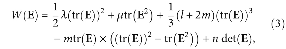 where l, m, and n are Murnaghan constants, λ and μ are Lame’s constants, and tr() and det() denote the trace and the determinant, respectively, of the bracketed tensor. The first Piola-Kirchhoff stress tensor and the second Piola-Kirchhoff stress tensor are obtained using

 where I is the second-order identity tensor. And T1 can be decomposed into linear and nonlinear components. Then the equation of motion in the reference configuration can be written as

 where ρ0 is the mass density, ü = δ2u/δt2, and b is the Lorentz force which is the action of magnetic field (including the static magnetic field Bs and the alternating magnetic field Bd) and eddy current. The calculated Lorentz force is then applied to the elasto-dynamic equation as a body load. The acoustic wave passes the material boundary and creates dynamic electromagnetic fields in a conductive material exposed to a steady magnetic field, which then can be detected by a received EMAT. The inverse effect applies whereby the acoustic wave forces the charged particles to move with the aid of the magnetic field of permanent magnet bias. The dynamic electric field induced by the acoustic field in a specimen and the equation of receiving voltage E can be written as
 3. Numerical Simulations
In this section, the results are obtained from numerical simulations performed using COMSOL Multiphysics 4.3b, a commercial finite-element software. The schematic of the 2D model is shown in Figure 1. The modeling of Lorentz force generation process uses the AC/DC and Magnetic Fields module, and the modeling of propagation process uses the Structural Mechanics module.
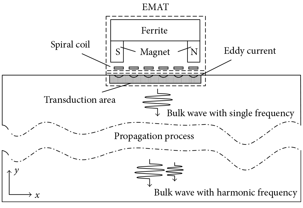
The electromagnetic acoustic transducer consists of a coil that provides a dynamic current and a U-shaped magnet providing a horizontal static magnetic field. While in the nonferromagnetic material, the ultrasonic wave is generated by the Lorentz forces. The Lorentz force is the interaction of the magnetic flux density and the eddy current. Thus, the electromagnetic field and mechanical field are coupled together by Lorentz forces in the transduction area.
The permanent magnet material feature is Nd-Fe-B with a remanence of 1.4 T. The horizontal static magnetic field acts parallel to the coil along the x-direction; there are also x-direction Lorentz forces present that are usually much smaller than that the y-direction Lorentz forces. The spiral coil consists of 35 wires with a diameter of 0.5mm and entangles together closely. The lift-off distance between the coil and the tested aluminum specimens is 0.5mm. The exciting coils are carrying a current signal of f = 500 kHz. The thickness of the transduction area is five times the skin depth, and a low reflecting boundary is used to reduce back reflections from the edge of the remote interfaces.

The ultrasonic wave is generated on the transduction area. The simulations were carried out using the Murnaghan model for aluminum, and the material properties are tabulated in Table 1. Quadrilateral elements are used to discretize the magnet and coil with a maximum element size of 0.5mm; the transduction area and propagation area are divided into triangular elements with a maximum element size of 0.1mm and 0.2mm.
3.1. Ultrasonic Wave Generation
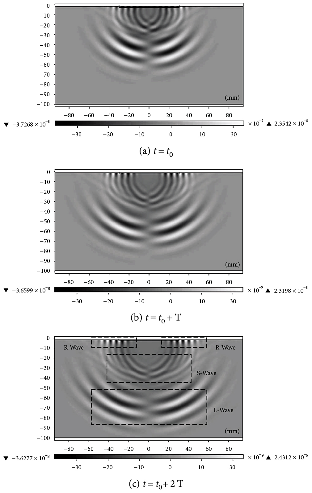
Due to the match of the coil and magnet, Rayleigh waves (R-Waves) travel along the surface, and simultaneously, the longitudinal waves (L-Waves) and shear waves (S-Waves) travel vertically into the specimen. Since S-Waves do not transfer energy to second harmonics [27], we investigate the nonlinear action of L-Waves and the contribution of the L-Waves, which are based on the x-direction Lorentz forces.
The x-component of the displacement is denoted by displacement “u,” the y-component is denoted by displacement “v,” and the direction of L-Waves vibration keeps consistent with the direction of L-Waves travelling. So displacement “v” is only considered. Figure 2 shows the geometric dimension of the test specimen (100mm x 180mm) and the spread of ultrasonic wave inside the x– and y-coordinates which represent the cross-sectional displacement “v” view of the wave modes propagating in two transmission cycles (from t0 to t0+ 2T). The R-Waves velocity vR, the S-Waves velocity vS, and the L-Waves velocity vL can be calculated by the time and the distance of flight between the two positions: vR = 2,915 m/s, vS = 3,122 m/s, and vL = 6,198 m/s. Thus, with the increase of propagation time, the separation of various ultrasonic waves is more clear.
3.2. Nonlinear Ultrasonic Propagation
In typical EMAT configurations where the frequency is of the order from several hundreds of kHz to a few MHz, the amplitude of Lorentz force depends on the characteristic of the static magnetic field, the exciting current, the construction of the spiral coil, and the lift-off. In order to eliminate the contribution of the second harmonic frequency due to alternating Lorentz force, the loading of body force is just applied by static Lorentz force bL,S in numerical model. So, the results were obtained for ultrasonic wave at fundamental frequency. Then we discuss the contribution of material and geometric nonlinearities to the second harmonic generation in the specimen. The displacement “v” amplitude of L-waves should reach 1E — 8 m, and the exciting current condition chosen is 150 A; some nonlinear effects are not easily decipherable at lower amplitudes. The results for three nonlinear mechanisms are presented in Table 2.
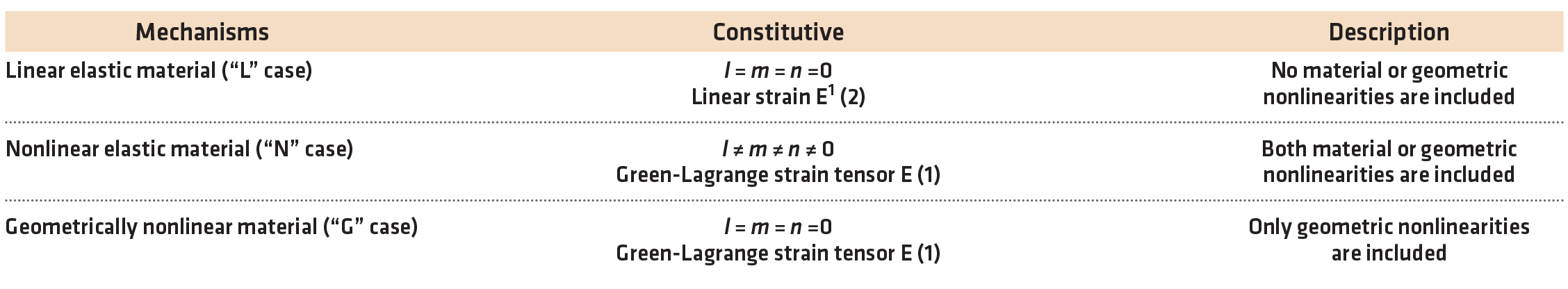
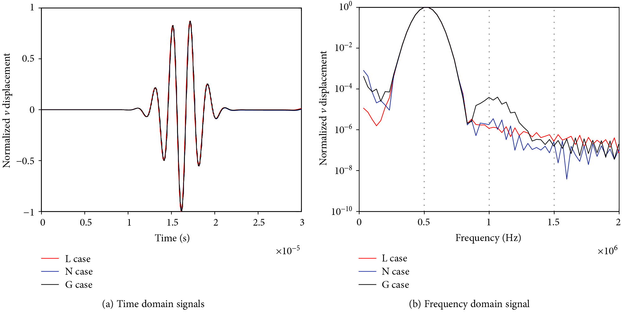
Figure 3 illustrates the normalized time domain signal obtained for the displacement “v” at position (10 mm, -100 mm). It shows that the signals overlapped nearly for the three cases, and the difference is barely visible. So, the velocities of L-Waves are kept consistent in each. But in the frequency domain, as shown in the normalized logarithm processing of the fast Fourier transform (FFT) method in the figure, nonlinearity is evident from the nonlinear presence of zero-frequency and second harmonic components in the “v” displacement of “N” and “G” cases. And the amplitude of the second harmonic generated in the “N” case is several times greater than that generated in the “G” case. This shows that the second harmonic generation is dominated by the material nonlinearity as opposed to geometric nonlinearity. The same explanations were adapted to obtain the main mechanism of zero-frequency components, which is dominated by geometric nonlinearity, while the “L ” case shows only fundamental frequency without any frequency components.
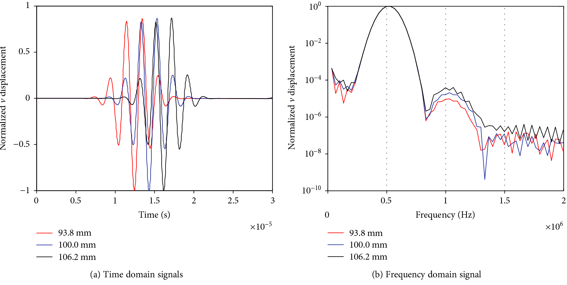
The displacement “v ” were obtained at positions (10, -93.8 mm), (10, -100 mm), and (10, -106.2mm) where the length of each propagation distance is one fundamental L-Waves wavelength. Figure 4 shows the normalized time domain signal and normalized logarithm processing of FFT. As predicted by theory, the amplitude of the second harmonic increases with the propagation distance. Then we discussed the effect of scaling higher-order elastic constants on the harmonic generation that increases with the degree of material damage.
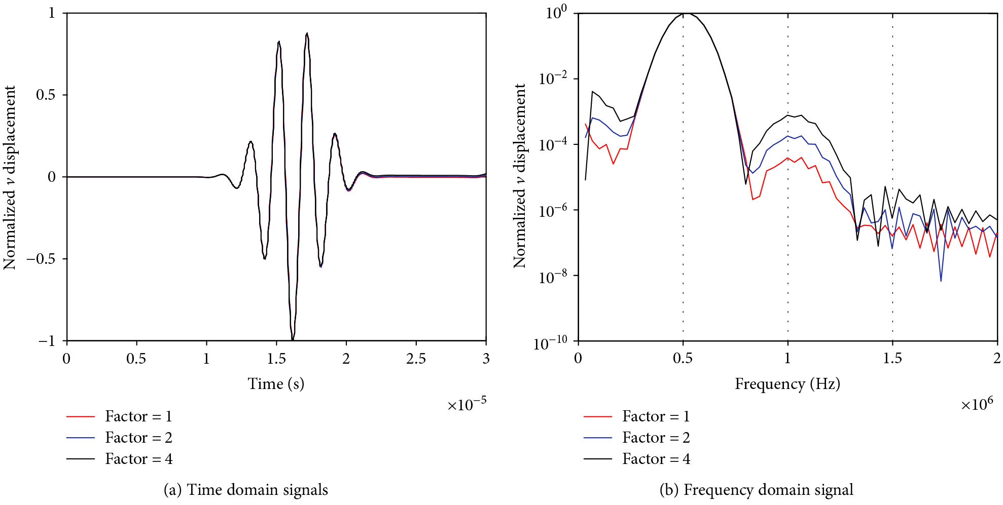
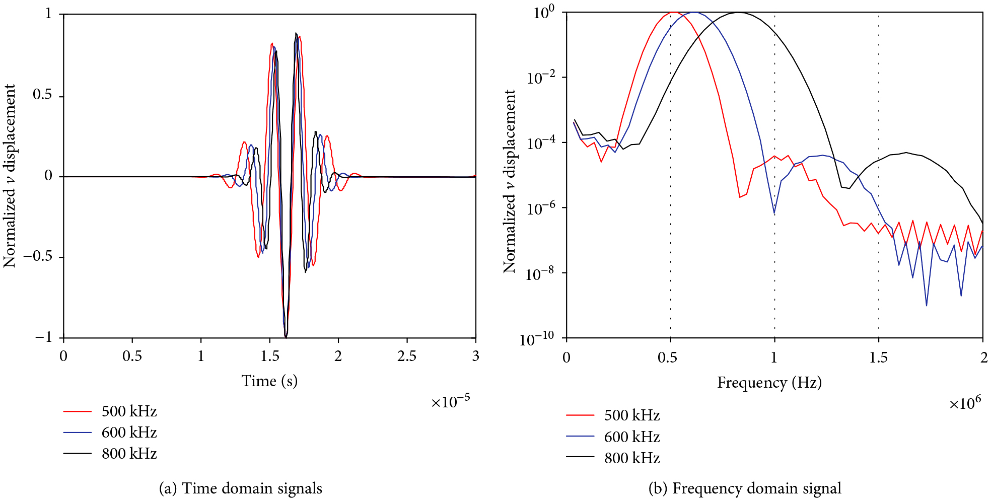
Simulations for the “N ” case used three different sets of higher-order elastic constants obtained by scaling Murnaghan constants by factors of 1, 2, and 4. Figure 5 shows the normalized time domain signal and normalized logarithm processing of FFT. As shown, the zero-frequency and second harmonic components are increasing with the factors. From another perspective, the degree of material damage increases with the nonlinear effects. In the following example, we present the results obtained for the second harmonic generation from the L-Waves at 500 kHz, 600 kHz, and 800 kHz in the “N ” case. As shown in Figure 6, the same presence of zero frequency and second harmonic components in the various frequencies, and the normalized amplitudes of zero frequency and second harmonic components remain the same.
4. Experimental Section
4.1. Sample Preparation
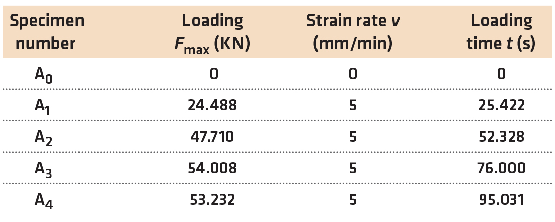
Tensile specimens made of aluminum alloy 6061 were fabricated for conducting the plastic deformation studies. The specimens were tensile loaded to various levels of elastic-plastic strain under strain control, as shown in Table 3. Among them, A0 was an undamaged specimen; A1 was a specimen which produced in the elastic tensile area; A2 was a specimen that produced in the elastic-plastic critical tensile area; A3 was a specimen that produced in the plastic tensile area, and A4 was a fractured specimen. The noncontact nonlinear characteristics were evaluated after unloading these specimens.
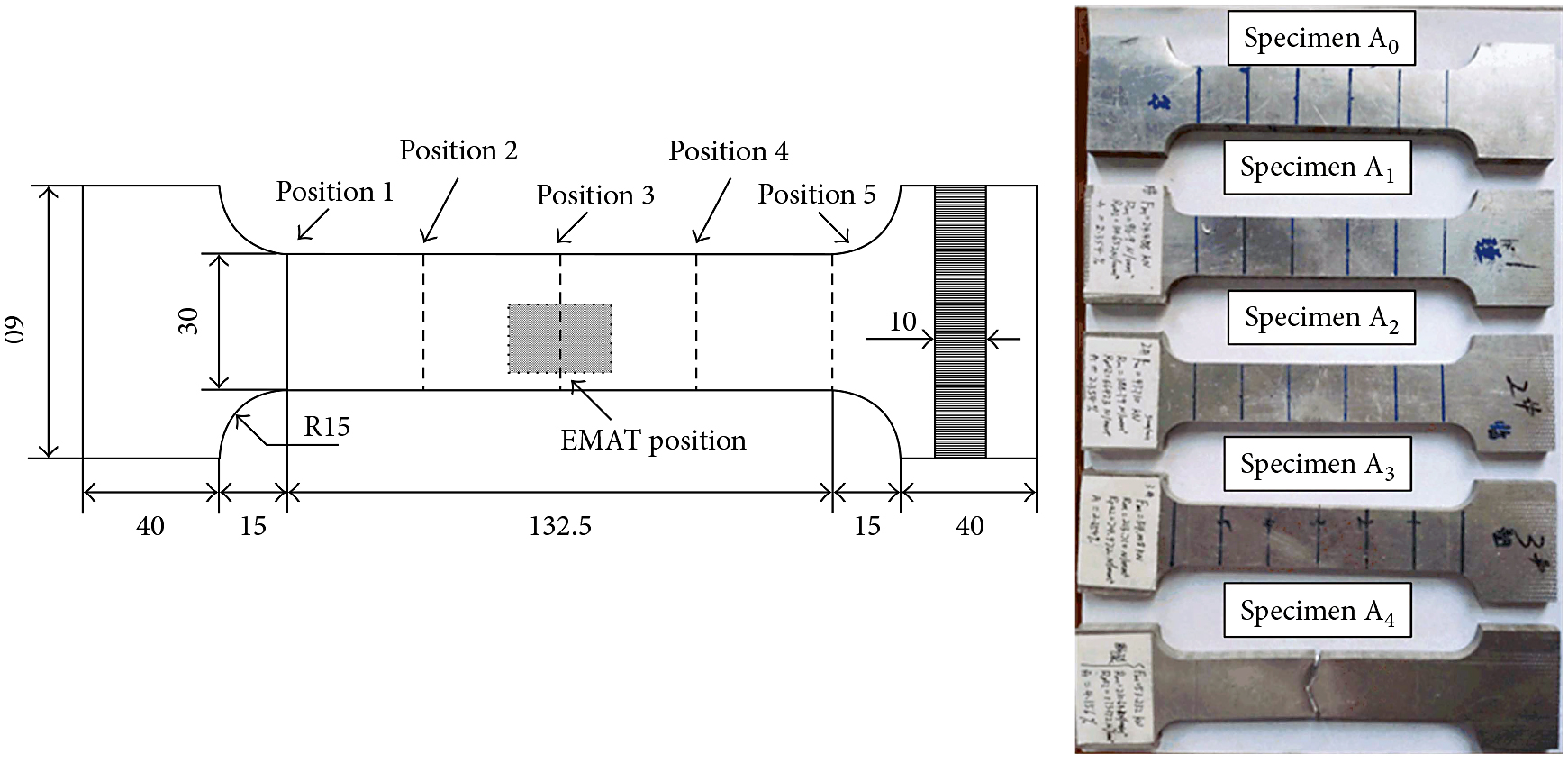
Nonlinear longitudinal wave was monitored at different positions along the length direction of tensile specimens for each sample. Figure 7 shows the positions of measurement along the thickness direction; each position is evenly spaced. The specimens are subjected to a uniaxial tensile test. The deformation is such that the material presents an elastoplastic behavior with nonlinear isotropic hardening. When subjected to such large deformations, the specimen experiences a significant plastic deformation and necking in its central cross section, and so nonlinear ultrasonic wave response at each position is various for one loading condition.
4.2. Nonlinear Ultrasonic Measurement Strategy
Figure 8 shows the nonlinear electromagnetic acoustic measurement. The nonlinear response of tensile specimen aluminum alloy was excited by using a RITEC SNAP RAM-5000 high power system (RITEC Inc., Warwick, RI, USA), and the high amplitude sinusoidal tone burst inputs with a few number of cycles at a stable single frequency.
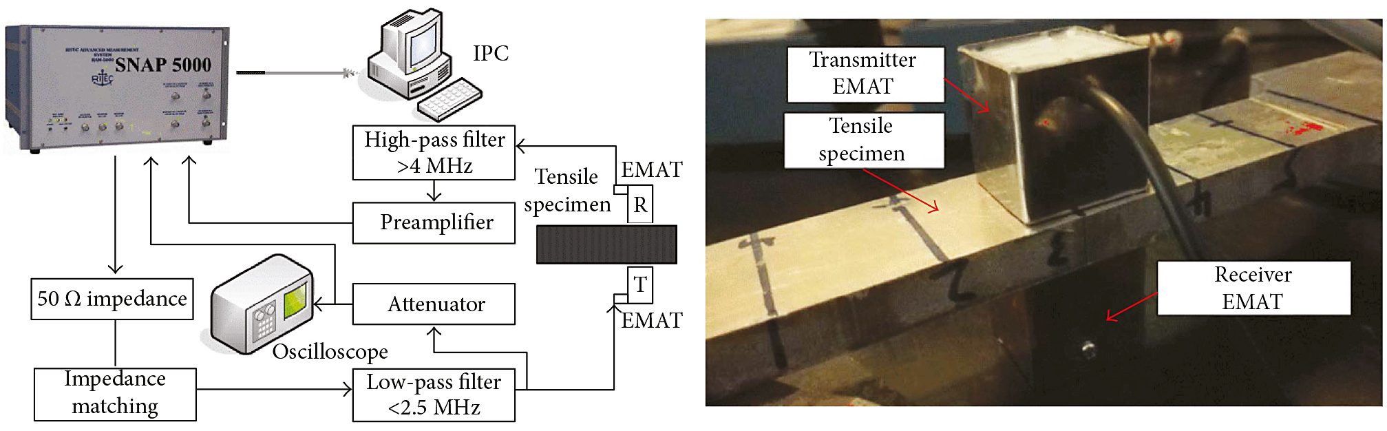
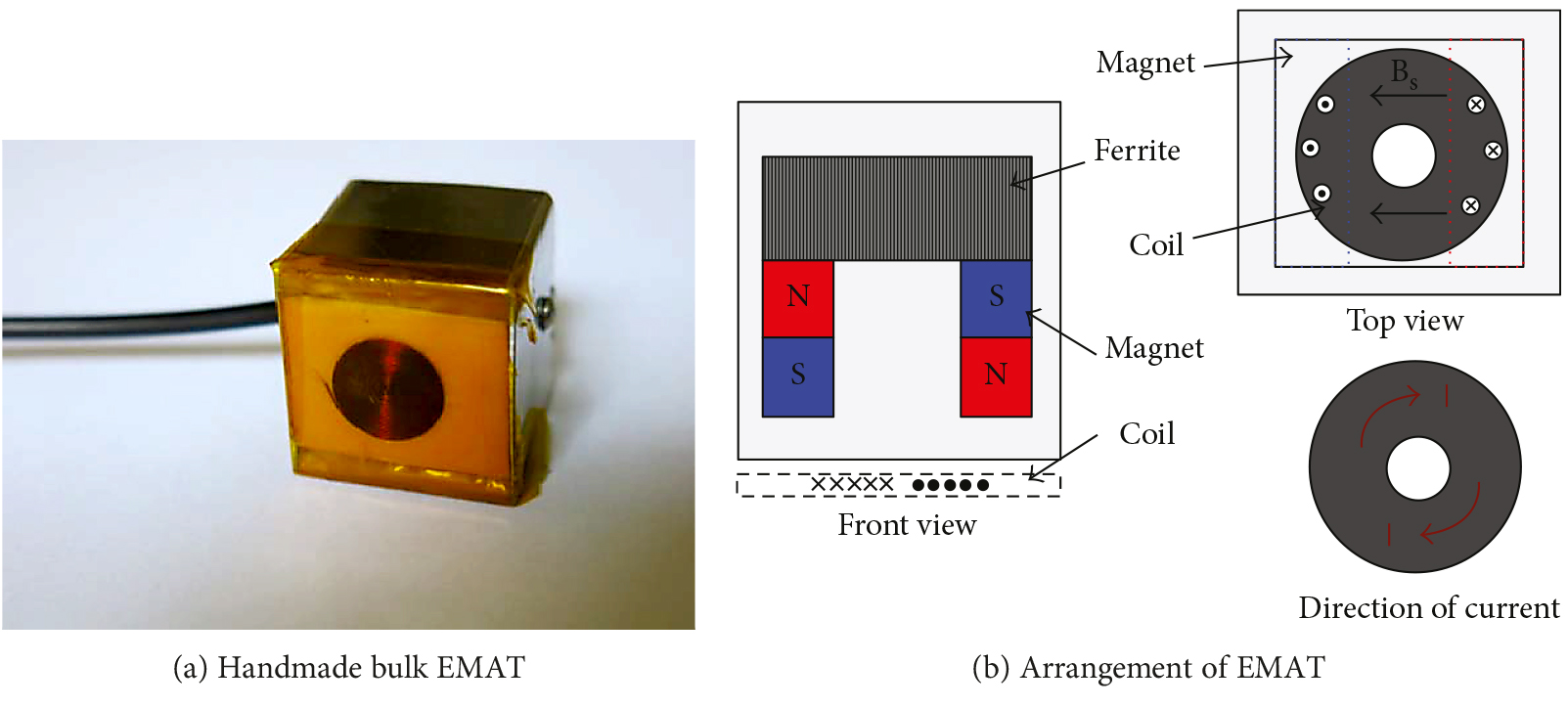
A pair of EMAT transducers are placed on the double sides of the specimen (through the thickness) as shown in Figure 9.
The EMAT transducer is mainly combined by a coil and permanent magnet. A toothpick is used to wind the copper wire with a diameter of 0.1mm; each turn is paralleled so closely that a large radius of spiral coil is obtained. The spiral shape of the EMAT coil is kept by laying an epoxy adhesion bond. BNC cable is connected to the spiral coil, and the permanent magnet is put on top of the coil. The bulk EMAT is facilitated after padding insulating polymer. The combination of a U-shape magnet provides a horizontal-bias magnetic field, and the spiral coil exerts high-frequency current excitation, so the electromagnetic force is mainly in a vertical direction; the particle in the skin depth will be affected by the electromagnetic force and produce a high vertical frequency vibration. The high vertical vibration producing ultrasonic bulk waves would spread in the specimen. One of the transducers acts as the transmitter, sending the bulk wave (mainly, longitudinal wave) across the specimen, and the other transducer plays the role as the receiver based on the principle of electromagnetic induction. Hence, the longitudinal wave propagates along the thickness direction of the specimen, and the received longitudinal wave would contain nonlinear information through the propagation path.
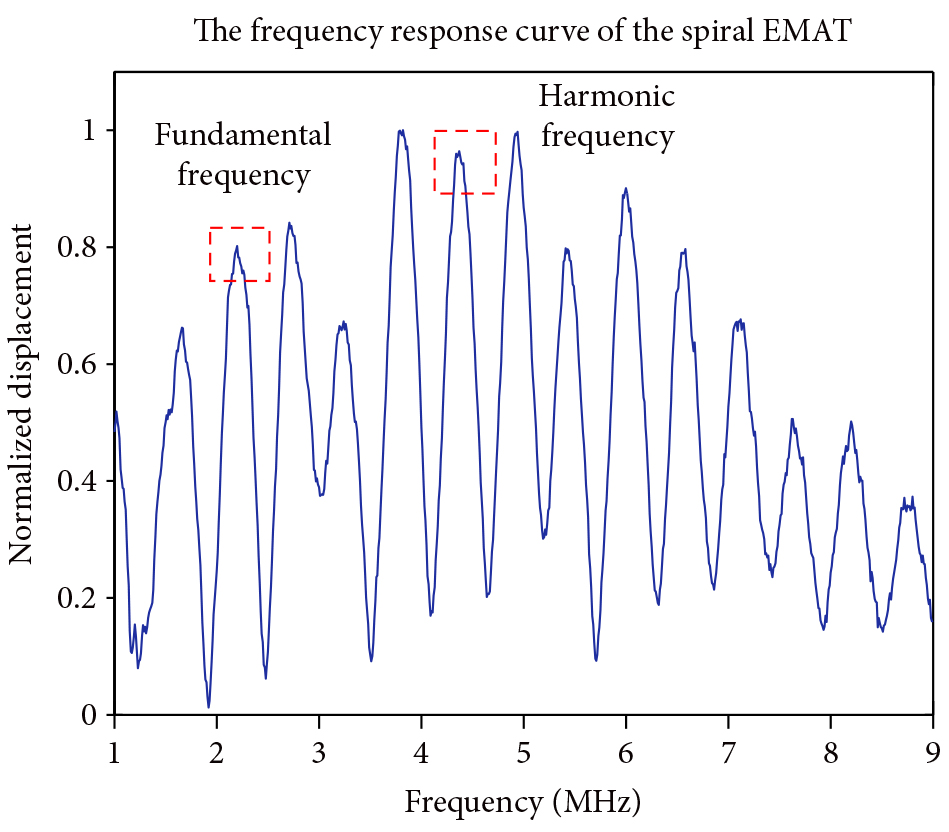
However, since this measurement by noncontact method EMAT has lower transduction efficiency, to avoid this inconvenience, additional devices are required to maintain the noncontact method by impedance matching and a high-pass filter. The exciting current has no window function in order to improve the exciting energy, which are from the high-power system to the EMAT transducers. Meanwhile, the exciting frequency should be considered by the designed EMAT frequency spectrum response curve as shown in Figure 10. These two EMAT transducers have the same designed size; thus, the exciting frequency has to be set 2.2 MHz, and the fundamental frequency 2.2MHz and the harmonic frequency 4.4MHz can be received at the peak frequency spectrum.
5. Analysis
Nonlinear longitudinal wave measurement along the thickness direction of the Al 6061 plates are performed with the EMAT and PZT setup, and no near sound field effects are observed in this experimental setup with the suited selection of exciting condition.
5.1. Nonlinear PZT Measurement
The nonlinear parameter β indicates that a linear relationship between the second harmonic amplitude A2 and the square of the fundamental amplitude (A12 ). Since measurement of fundamental and second harmonic response by received ultrasonic sensor is in terms of the several voltages excitation, and β can be predicted by the microplasticity model as a function of the tensile stress with few influence of different exciting frequencies [7], so a 5MHz excited PZT sensor and a 10MHz received PZT sensor were employed through the thickness direction to implement generated longitudinal wave.
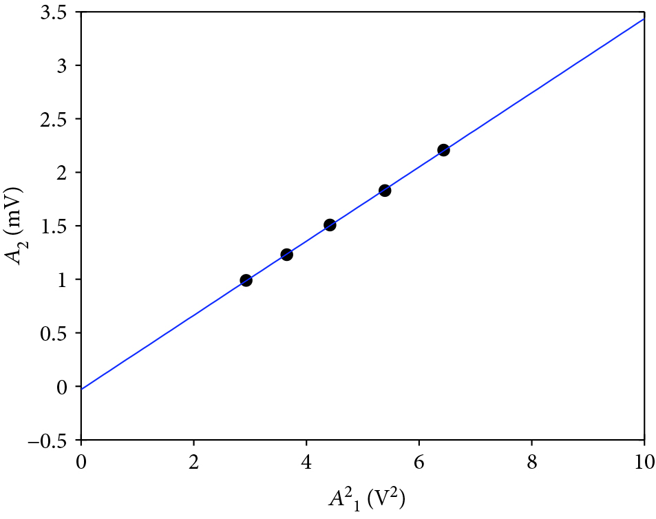
Figure 11 shows a variation amplitude of A2 with A12 at the position 3 of specimen A0; the black spots are experimental data points at 10∼50 level exciting voltages, and a linear fitting line of A2 vs. A12 for different driving voltages is clearly obtained, which means that the nonlinear parameter keeps constant for different voltages. The slope of this linear fitting line is the value of the nonlinear parameter βp0, and βp0 mainly includes material nonlinearity βp0 and contact nonlinearity βc0 .
Consider the fluctuation of frequency response curve of PZT sensors (the frequency response at 5MHz and 10MHz points have disaffinity) and the influence of the nonuniform unit. Hence, the normalized nonlinear coefficient is β’p0 (the ratio between the nonlinear parameter measured in the tensile damage specimen to βp0), that is, β’p0 = βp/βp0 .
5.2. Compared with Nonlinear EMAT Measurement
In this EMAT measurement study, the lower transduction efficiency of EMAT is considered, as shown in Figure 12. EMAT has low energy converting efficiency and is sensitive to noise.
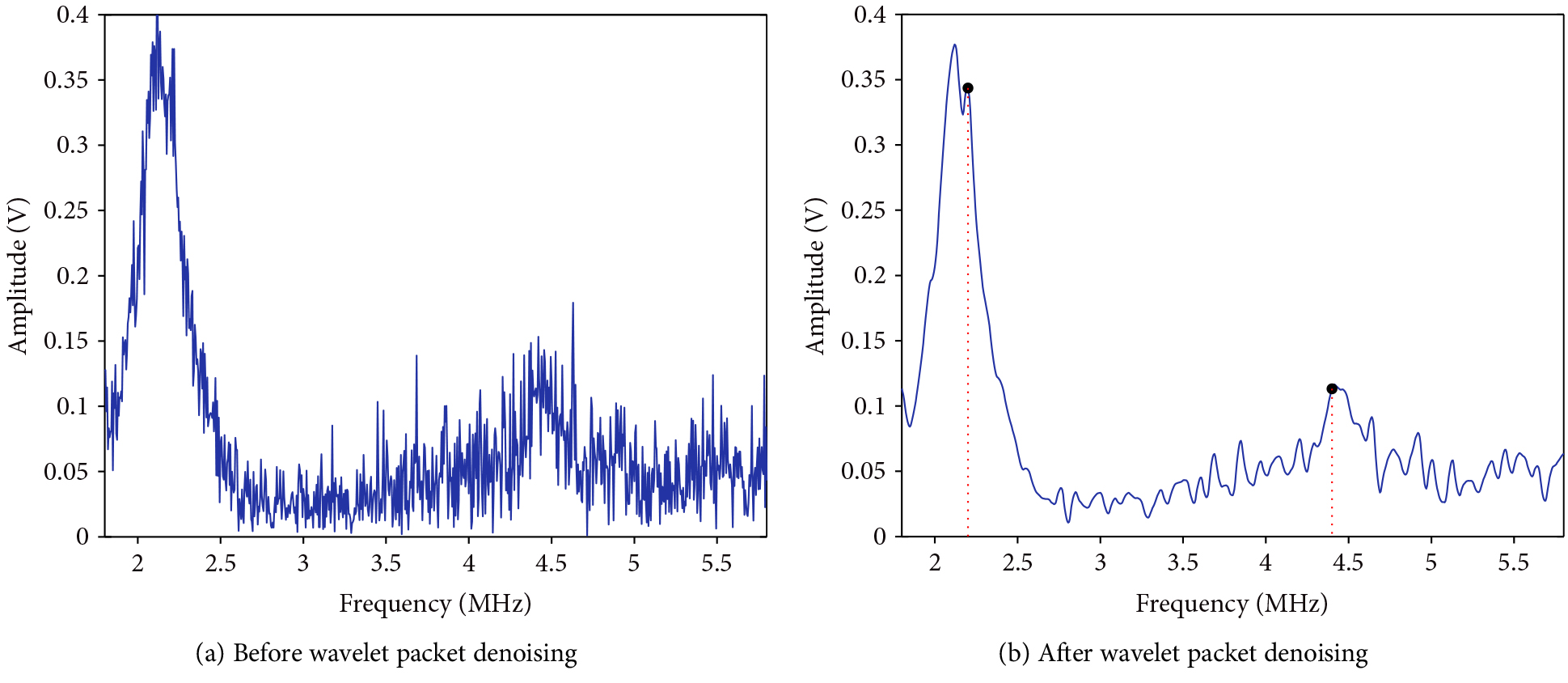
The noise interference is mainly composed of continuous interference noise, paroxysmal interference noise, and electromagnetic noise, which are generated by the operation of the tested equipment and alternating electromagnetic fields in the limited space volume of the electromagnetic ultrasonic transducer. In order to realize the effective recognition of ultrasonic echo signal, the frequency-domain signal needs to be received with 40 dB attenuation of low-frequency stage and 60 dB amplification of high-frequency stage, where one can clearly find the contributions of the fundamental and second harmonic waves. Meanwhile, the frequency domain signal is filled with noise spectrum. To obtain the amplitudes of the fundamental and second harmonic wave components, Daubechies wavelet function and third wavelet packet decomposition levels were adopted to denoise as shown in Figure 12. In order to compare with the measurement by PZT sensor, and the nonlinear parameter βE0 should be normalization processing by noncontact EMAT measurement, the normalized nonlinear coefficient β’E0= βE/βE0.
Figure 13 shows the comparison of the relative nonlinear coefficients by the two methods. With the same loading, the variation tendency of the relative nonlinear coefficients stayed the same.
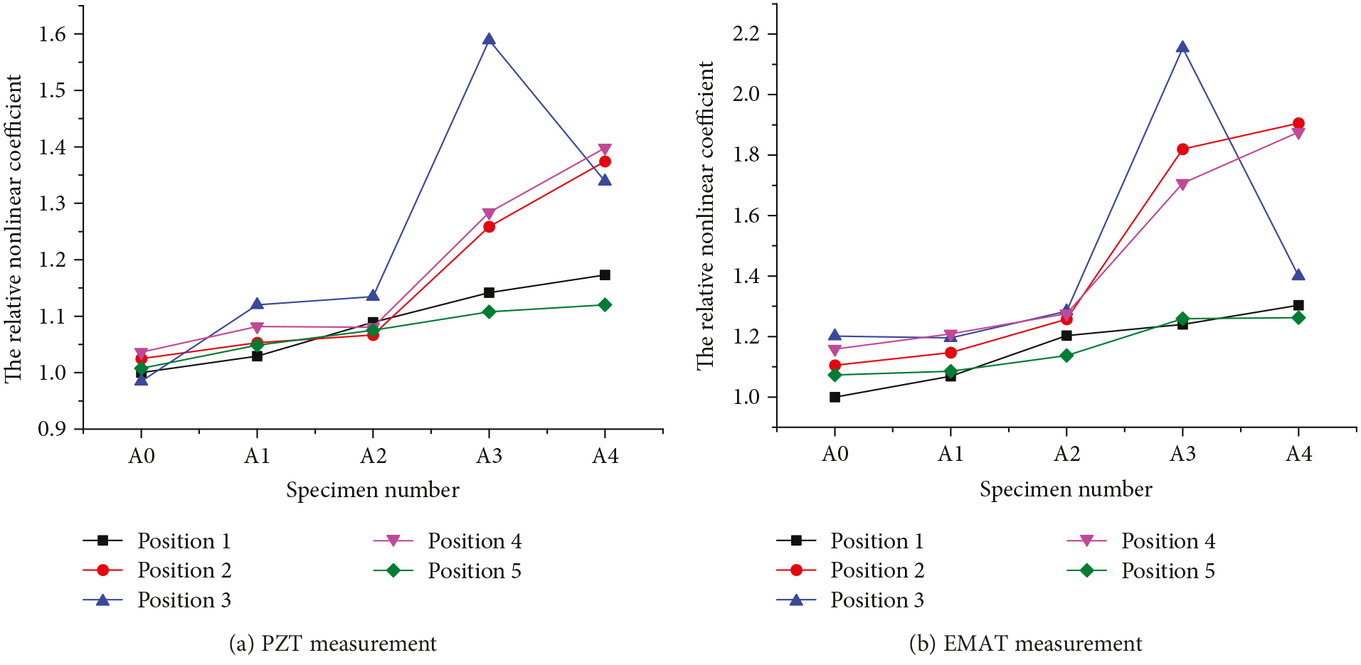
With elastic tensile loading (Fmax < 47.71 kN), the relative nonlinear coefficients nearly keeps unchanged; thus, the elastic constant changes very little and increases rapidly when the tensile loading exceeds 47.71 kN at the position of 2, 3, and 4. Plastic deformation starts to exist at these positions; meanwhile, the relative nonlinear coefficients change very little at positions 1 and 5. It can be found that the plastic deformation is symmetrically distributed along the center specimen position (position 3) by tensile loading, and based on the metal necking effect, the plastic deformation is most notable at position 3. When the tensile loading exceeds 53.232 kN, the relative nonlinear coefficient drops rapidly, occurring with the more discontinuous area; at the same time, the plastic deformations at the position of 2 and 4 are still in the hardening stage and the relative nonlinear coefficients are still increasing.
It can be seen that the EMAT ultrasonic measurement is bigger than that of the PZT ultrasonic measurement. Namely, β’E0 > β’p0, compared with what constitutes the two relative nonlinear coefficients, it is the contact nonlinearity (the influence of couplant and rough surface), which mainly causes the decrease in relative nonlinear coefficients. The result also shows that the change of the plastic nonlinearity on the plastic deformation can be measured using the proposed noncontact ultrasonic method, and the relative nonlinear coefficients measured by EMAT ultrasonic have potential applications in detecting variation tendency of plastic deformation under extreme environments.
6. Conclusions
In this article, tensile damage behavior of nonlinear longitudinal wave was investigated. From the numerical perspective, simulations of EMAT transduction and ultrasonic wave propagation were carried out in COMSOL Multiphysics 4.3b using the Murnaghan hyperelasticity model, harmonic generation from the fundamental longitudinal wave, while time domain signals show very small difference. The contribution of material nonlinearity, geometric nonlinearity, damage cased nonlinearity, and propagation distance cased nonlinearity to the harmonic generation is discussed. As the accumulated material damage is typically inferred from the nonlinear coefficient, which in turn depends on the higher Murnaghan constants and longer propagation distances, the exciting frequency is not inferred from the nonlinear coefficient.
From the experimental perspective, this research demonstrates the feasibility and robustness of noncontact EMAT method for the nonlinearity measurement with a longitudinal wave; thus, the surface condition of the specimen is relatively not important. The experimental setup provides an output signal with low SNR; meanwhile, wavelet denoising method can improve the SNR and extract nonlinearity information from measuring frequency signals.
The results obtained in this research demonstrate that the noncontact, EMAT detection method provides potential field applicability for the in-situ measurements of the relative nonlinearity parameter in online structures. Further work needs to be done to identify the fatigue damage of ferromagnetic structure by EMAT method based on the magneto-strictive mechanism.
Conflicts of Interest
The authors declare that there is no conflict of interest regarding the publication of this paper.
Acknowledgments
This work was supported by the Natural Science Foundation of Jiangxi Province (Grant no. 20171BAB216035) and Science Foundation of Jiangxi Provincial Department of Education “Plastic damage detection method in metallic components based on electromagnetic transduction”. (Grant no. GJJ170409).
References
- L. R. Joseph, Ultrasonic Guided Waves in Solid Media, Cambridge University Press, New York, NY, USA, 2014.
- K. H. Matlack, J. Y. Kim, L. J. Jacobs, and J. Qu, “Review of second harmonic generation measurement techniques for material state determination in metals,” Journal of Nondestructive Evaluation, vol. 34, no. 1, p. 273, 2015.
- J. H. Cantrell and W. T. Yost, “Effect of precipitate coherency strains on acoustic harmonic generation,” Journal of Applied Physics, vol. 81, no. 7, pp. 2957–2962, 1997.
- J. S. Valluri, K. Balasubramaniam, and R. V. Prakash, “Creep damage characterization using non-linear ultrasonic techniques,” ActaMaterialia., vol. 58, no. 6, pp. 2079–2090, 2010.
- G. Shui, Y. Wang, P. Huang, and J. Qu, “Nonlinear ultrasonic evaluation of the fatigue damage of adhesive joints,” NDT & E International, vol. 70, pp. 9–15, 2015.
- X. Wan, Q. Zhang, G. Xu, and P. W. Tse, “Numerical simulation of nonlinear lamb waves used in a thin plate for detecting buried micro-cracks,” Sensors, vol. 14, no. 12, pp. 8528–8546, 2014.
- A. Ruiz, N. Ortiz, A. Medina, J. Y. Kim, and L. J. Jacobs, “Application of ultrasonic methods for early detection of thermal damage in 2205 duplex stainless steel,” NDT and E International., vol. 54, pp. 19–26, 2013.
- G. Shui, Y. Wang, and F. Gong, “Evaluation of plastic damage for metallic materials under tensile load using nonlinear longitudinal waves,” NDT & E International., vol. 55, pp. 1–8, 2013.
- J. Frouin, S. Sathish, T. E. Matikas, and J. K. Na, “Ultrasonic linear and nonlinear behavior of fatigued Ti–6Al–4V,” Journal of Materials Research., vol. 14, no. 4, pp. 1295–1298, 1999.
- H. Jeong, S. H. Nahm, K. Y. Jhang, and Y. H. Nam, “A nondestructive method for estimation of the fracture toughness of CrMoV rotor steels based on ultrasonic nonlinearity,” Ultrasonics, vol. 41, no. 7, pp. 543–549, 2003.
- D. C. Hurley, D. Balzar, and P. T. Purtscher, “Nonlinear ultrasonic assessment of precipitation hardening in ASTM A710 steel,” Journal of Materials Research., vol. 15, no. 9, pp. 2036–2042, 2000.
- J. Y. Kim, L. J. Jacobs, J. M. Qu, and J. W. Littles, “Experimental characterization of fatigue damage in a nickel-base superalloy using nonlinear ultrasonic waves,” The Journal of the Acoustical Society of America., vol. 120, no. 3, pp. 1266–1273, 2006.
- C. Pruell, J. Y. Kim, J. Qu, and L. J. Jacobs, “A nonlinear-guided wave technique for evaluating plasticity-driven material damage in a metal plate,” NDT and E International., vol. 42, no. 3, pp. 199–203, 2009.
- G. Choi, Y. Liu, X. Yao, and C. J. Lissenden, “Effect of localized microstructural evolution on higher harmonic generation of guided wave modes,” in 41st annual review of progress in quantitative nondestructive evaluation, pp. 1592–1598, Boise Idah, USA, 2014.
- T. Sebastian, J. Y. Kim, J. M. Qu, and L. J. Jacobs, “Air-coupled detection of nonlinear Rayleigh surface waves to assess material nonlinearity,” Ultrasonics, vol. 54, no. 6, pp. 1470–1475, 2014.
- P. Liu, H. Sohn, T. Kundu, and S. Yang, “Noncontact detection of fatigue cracks by laser nonlinear wave modulation spectroscopy (LNWMS),” NDT & E International, vol. 66, pp. 106– 116, 2014.
- M. Hirao and H. Ogi, Electromagnetic Acoustic Transducers: Noncontacting Ultrasonic Measurement Using EMATs, Springer, KK, Japan, Second Edition edition, 2016.
- M. Kogia, T. H. Gan, L. M. Balachandran et al., “High temperature shear horizontal electromagnetic acoustic transducer for guided wave inspection,” Sensors, vol. 16, no. 12, p. 582, 2016.
- H. Ogi, T. Ohtani, and S. Aoki, “Noncontact monitoring of surface-wave nonlinearity for predicting the remaining life of fatigued steels,” Journal of Applied Physics, vol. 90, no. 1, pp. 438–442, 2001.
- T. Ohtani, H. Ogi, and M. Hirao, “Noncontact evaluation of surface-wave nonlinearity for creep damage in Cr-Mo-V steel,” Japanese Journal of Applied Physics, vol. 48, no. 7, article 07GD02, 2009.
- A. Cobb, M. Capps, C. Duffer, J. Feiger, K. Robinson, and B. Hollingshaus, “Nonlinear ultrasonic measurements with EMATs for detecting pre-cracking fatigue damage,” in Review of Progress in Quantitative Nondestructive Evaluation, vol. 1430, pp. 299–306, Burlington, VT, USA, 2012.
- A. Cobb, E. Macha, J. Bartlett, and Y. Xia, “Detecting sensitization in aluminum alloys using acoustic resonance and EMAT ultrasound,” in , Article ID 05000143rd annual review of progress in quantitative nondestructive Evaluation, vol. 1806, Atlanta, GA, USA, 2016.
- C. Pei, P. Xiao, S. Zhao, and Z. Chen, “Development of a flexible film electromagnetic acoustic transducer for nondestructive testing,” Sensors and Actuators A: Physical., vol. 258, pp. 68–73, 2017.
- D. Rueter, “Experimental demonstration and circuitry for a very compact coil-only pulse Echo EMAT,” Sensors, vol. 17, no. 12, p. 926, 2017.
- V. K. Chillara and C. J. Lissenden, “Nonlinear guided waves in plates: a numerical perspective,” Ultrasonics, vol. 54, no. 6, pp. 1553–1558, 2014.
- K. Zhang, P. X. Yi, Y. H. Li, B. Hui, and X. Zhang, “A new method to evaluate surface defects with an electromagnetic acoustic transducer,” Sensors, vol. 15, no. 12, pp. 17420– 17432, 2015.
- L. Yang, V. K. Chillara, C. J. Lissenden, and L. Joseph, “Third harmonic shear horizontal and Rayleigh lamb waves in weakly nonlinear plates,” Journal of Applied Physics, vol. 114, no. 11, article 114908, 2013.


 general practice for CQI-9 and AMS2750E")


")


