


This paper focuses on recent inventions and innovations (from the past four-six years) in induction hardening of gears and gear-like components, including, but not limited to:
- “Know-how” in controlling distortion of induction-hardened gears
- Simultaneous dual-frequency induction hardening
- Advanced induction-hardening process recipes when hardening small and medium size gears
- Novel inductor designs to minimize distortion when induction hardening hypoid and spiral bevel gears
- IFP technology for induction gear hardening
- Induction tempering and stress relieving of gear-like components with improved temperature uniformity
This paper also provides a review of basic principles and applications devoted to induction hardening small, medium, and large gears using tooth-by-tooth techniques and encircling method.
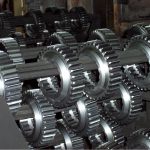
Depending upon the gear size, required hardness pattern, and tooth geometry, gears are induction hardened by encircling the whole gear with a coil (so-called “spin hardening of gears”), or for larger gears, heating them tooth-by-tooth [1-6].
“Tooth-by-tooth” Hardening
The tooth-by-tooth method comprises two alternative techniques: “Tip-by-tip” or “gap-by gap” hardening [1-4]. The “tip-by-tip” method can apply a single-shot heating mode or scanning mode; the “gap-by-gap” technique applies the scanning mode exclusively. Inductor scanning rates are typically within 6 mm/sec to 9 mm/sec. Both “tip-by-tip” and “gap-by-gap” techniques are typically not very suitable for small and fine-pitch gears (modules smaller than 6) [1,2].
During “tip-by-tip” hardening, an inductor encircles a body of single tooth. Presently, this technique is not used because the hardening patterns typically do not provide the required fatigue and impact strength. “Gap-by-gap” hardening is a much more popular technique compared to “tip-by-tip” method. This is the reason why the term “tooth-by-tooth” hardening is often associated with the “gap-by-gap” hardening method. “Gap-by-gap” hardening requires the inductor to be symmetrically located between two flanks of adjacent teeth. Inductor geometry depends upon the shape of the teeth and the required hardness pattern. Special locators (probes) or electronic tracing systems are often used to ensure proper inductor positioning in the tooth space.
Two scanning techniques used include one in which the inductor is stationary and the gear is moveable, and the other in which the gear is stationary and the inductor is moveable. The latter technique is more popular when hardening large gears. Inductors can be designed to heat only the root and/or flank of the tooth, leaving the tip and tooth core soft, tough, and ductile (Figure 1). Though this is one of the oldest hardening techniques, recent innovations continue improving quality of gears heat-treated using this method.
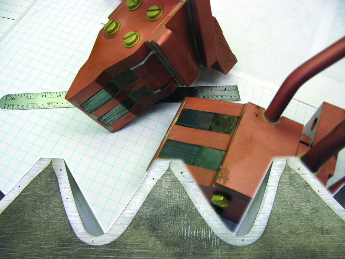
outside (Courtesy of Inductoheat Inc.)
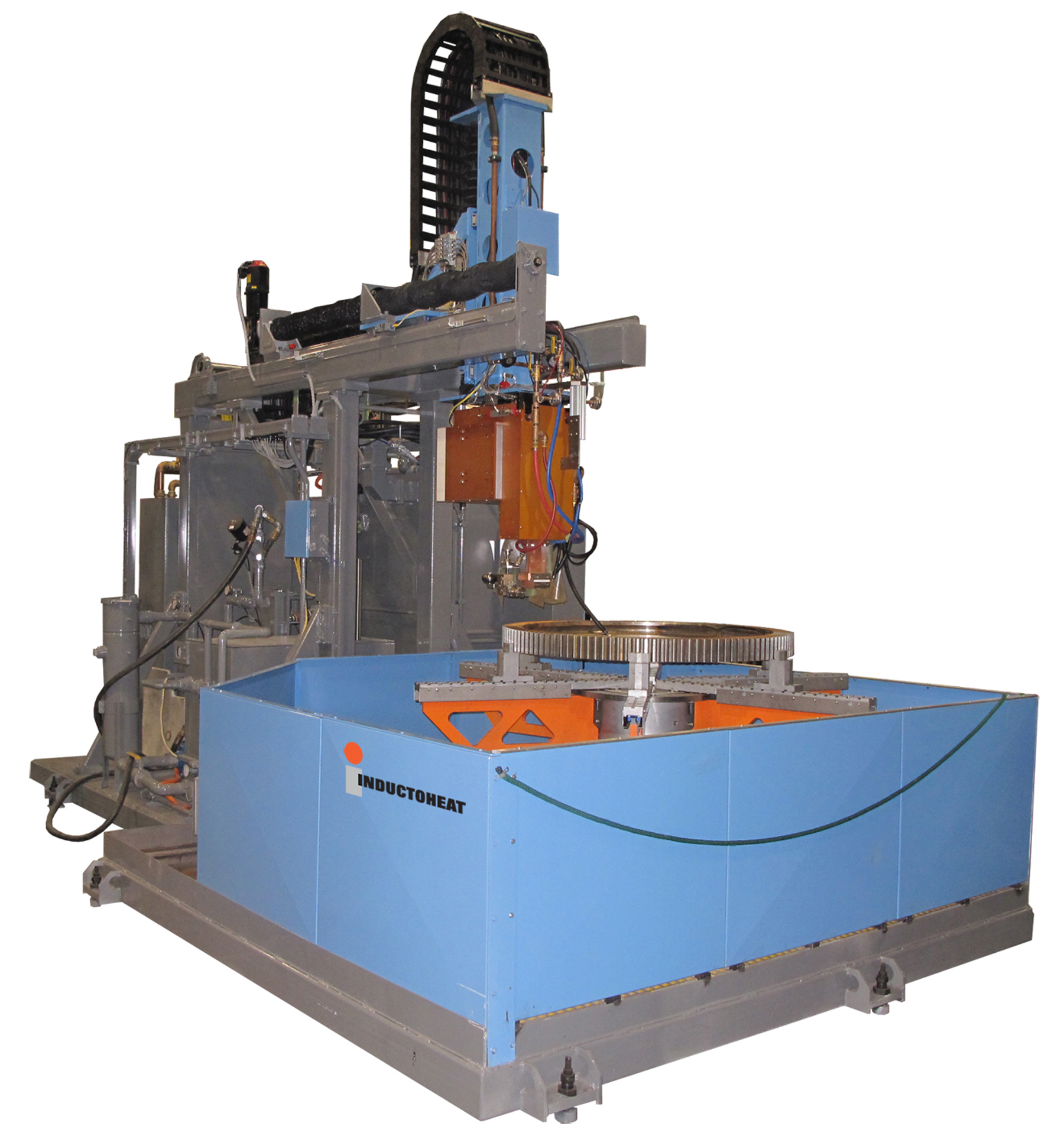
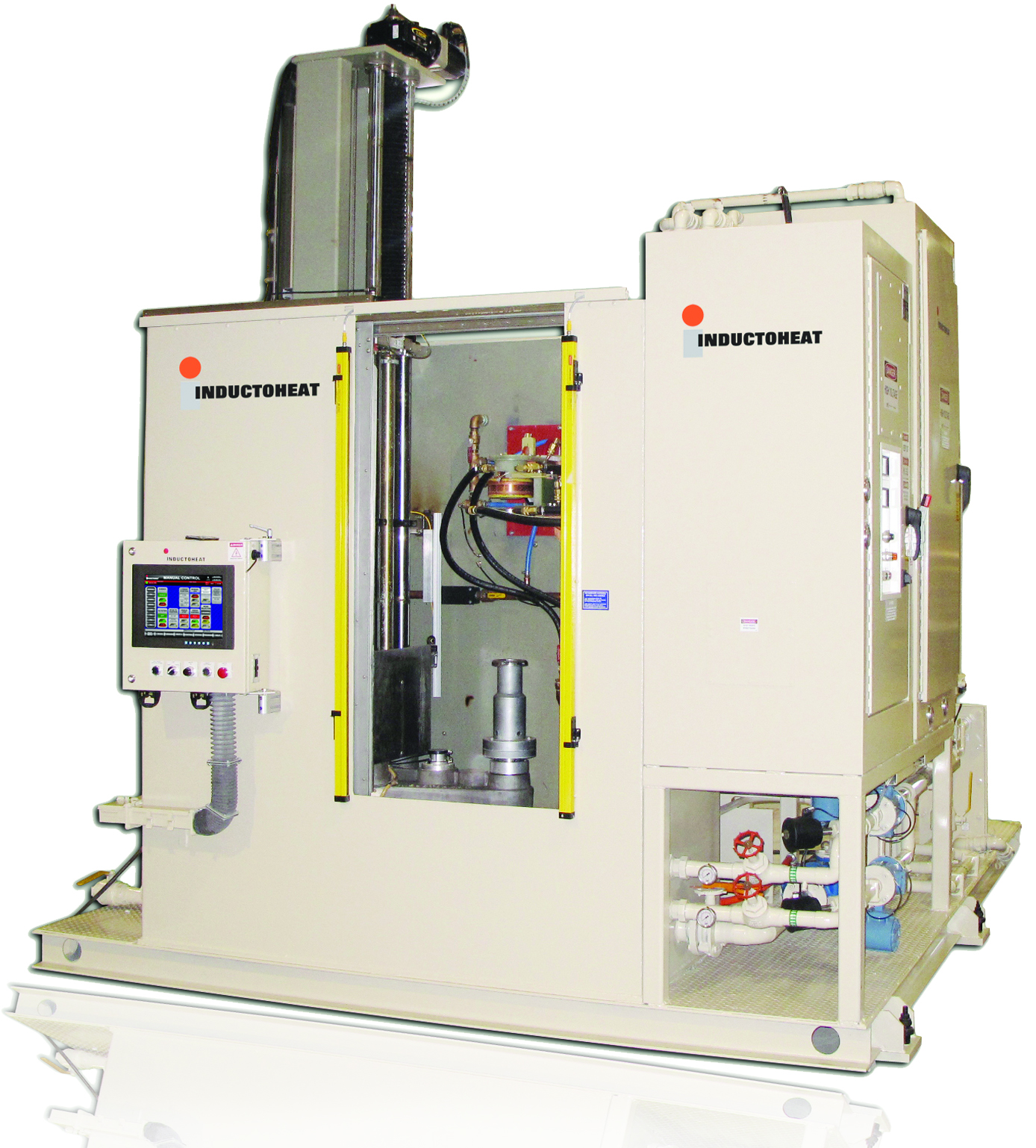
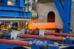
Thermal expansion of metal during the heating should be taken into consideration when determining and maintaining the proper inductor-to-tooth air gap. After gear loading and initial inductor positioning, the process runs automatically, based on an application recipe. Figure 2 shows examples of induction using a tooth-by-tooth hardening machine.
When developing tooth-by-tooth gear hardening process, particular attention should be paid to electromagnetic end/edge effects and the ability to provide the required pattern in the gear end areas. Upon scanning gear tooth, the temperature is distributed within gear roots and flanks quite uniformly. At the same time, since the eddy current makes a return path through the flank and, particularly through the tooth tip, proper care should be taken to prevent overheating the tooth tip regions, particularly at the beginning and end of the scan hardening. Improved system design helps to maintain required hardness uniformity.
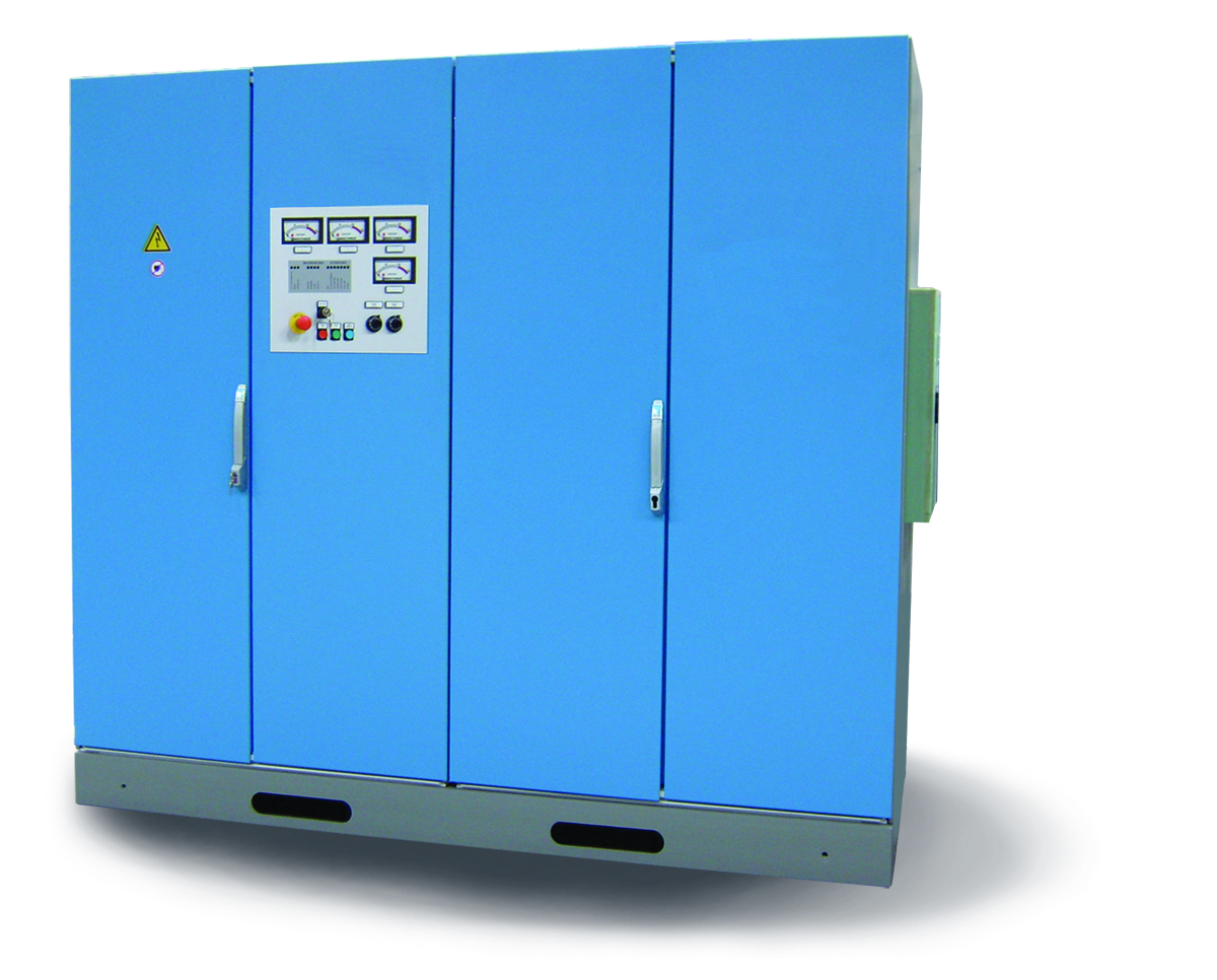
Specifics of gear geometry demand a particular process control algorithm. In the past, the process control recipe was limited to an available variation of power and scan rate vs. inductor position. Recent innovations bring the unique ability of Inductoheat’s novel inverters to independently control both power and frequency during scanning operation, which optimizes electromagnetic and thermal conditions at initial, intermittent, and final stages of scanning. As an example, Figure 3 shows the STATIPOWER® IFPt (Independent Frequency and Power Control) inverter. The ability to independently change the frequency and power of an induction system during the scanning process represents the long-awaited dream of commercial induction heat treaters, since such type of setup would provide the greatest process flexibility. STATIPOWER® IFPt is a novel IGBT-type power supply specifically designed for hardening and tempering applications, allowing independently adjustable frequency via CNC-program in a 5-40kHz frequency range and power in the range of 10-360kW. This concept substantially expands heat treat equipment capabilities for processing parts by programming power and/or frequency changes on the fly, maximizing heating efficiency and temperature uniformity while heating complex geometry components.
Gear Spin Hardening (Encircling Inductors)
Spin hardening is the most popular approach for induction hardening gears with fine and medium-size teeth. Gears are rotated during heating to ensure an even distribution of energy. Single-turn or multi-turn inductors that encircle the whole gear can be used [1,3- 6]. When applying encircling coils, it is possible to obtain substantially different hardness patterns by varying process parameters.
As a rule, when it is necessary to harden only the tooth tips, a higher frequency and high power density should be applied; to harden the tooth roots, use a lower frequency. A high power density in combination with the relatively short heat time generally results in a shallow pattern, while a low power density and extended heat time produces a deep pattern with wide transition zones.
Quite often, to prevent problems such as pitting, spalling, tooth fatigue, and endurance and impact limitations, it is required to harden the contour of the gear, or to have gear- contour hardening (Figure 4). This often also maximizes beneficial compressive stresses within the case depth and dramatically minimizes distortion of as-hardened gears keeping it under 80-100 microns (0.003” – 0.004”).
Many times, obtaining a true contour-hardened pattern can be a difficult task, due to the difference in current density (heat source) distribution and heat transfer conditions within a gear tooth.
Simultaneous Dual Frequency Gear Hardening
Some induction practitioners have heard about simultaneous dual frequency gear hardening, which utilizes two appreciably different frequencies working on the same coil at the same time [6]. Low frequency helps to austenitize the roots of the teeth and high frequency helps to austenitize the teeth flanks and tips.
However, it is not advantageous have two different frequencies working simultaneously all the time. In some cases, it is preferable to apply lower frequency at the beginning of the heating cycle and after achieving a desirable root pre-heating, the higher frequency can be used instead of or simultaneously with lower frequency, completing a job by working together.
Figure 5 shows Inductoheat’s single-coil dual frequency system, comprised of medium- (10kHz) and high-frequency (120 to 400kHz) modules working simultaneously, or in any sequence desirable, to optimize properties of the heat-treated gears [6]. Total power exceeds 1,200kW. As expected, smaller gears will require less power. Heat time usually does not exceed 2 seconds and often is less than 1.5sec.
Inductoheat’s simultaneous dual frequency induction gear hardening system (Figure 5) also has some “auto-match” features to simplify tuning. It is rugged and can be used for high-volume single-shot hardening of a variety of powertrain components, dramatically minimizing distortion of heat-treated parts and providing a superior hardness pattern with favorable distribution of residual stresses.
A Novel Development in Induction Gear Hardening: TSH Steels
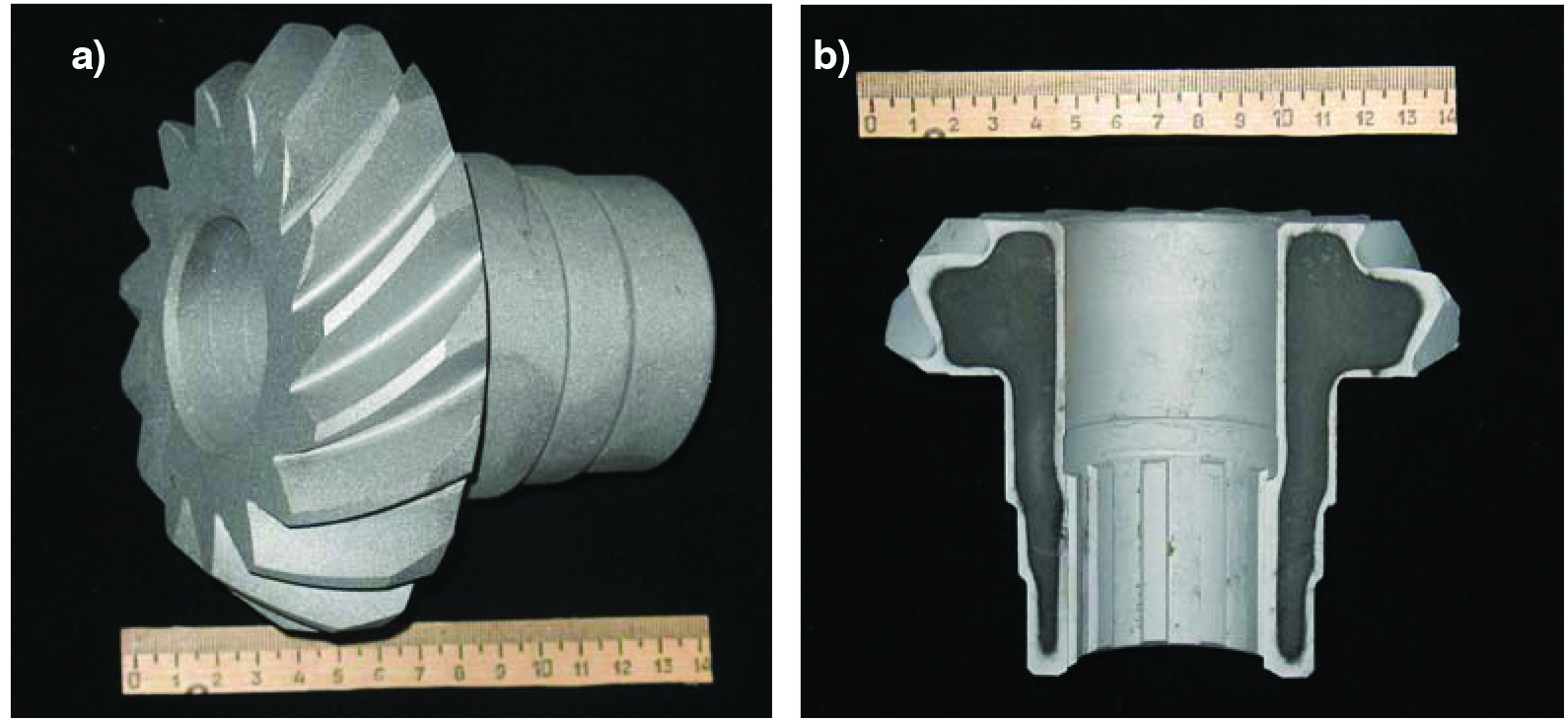
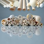
There was a belief that not all gears and pinions were well-suited for induction hardening. Hypoid and bevel gears, spiral bevel automotive pinions, and noncircular gears used to be rarely induction hardened. Those gears were typically carburized. This situation has changed. As an example, Figure 6a and Figure 6b show an example of inductively case-hardened components utilizing TSH Technology [7,8].
TSH steels are low-hardenability (LH) low-alloy steels, characterized by limited hardenability and a reduced tendency for grain growth at austenizing temperatures suitable for hardening. They can be substituted for standard steels typically used for conventional induction hardening or carburizing grades. TSH steels have significantly less alloying elements such as manganese, molybdenum, chromium, and nickel than the majority of conventional low-alloy steels. Their chemical composition is somewhere between micro-alloy steels and plain carbon steels, providing fine-grain martensite with extremely high compressive stresses at the tooth surface.
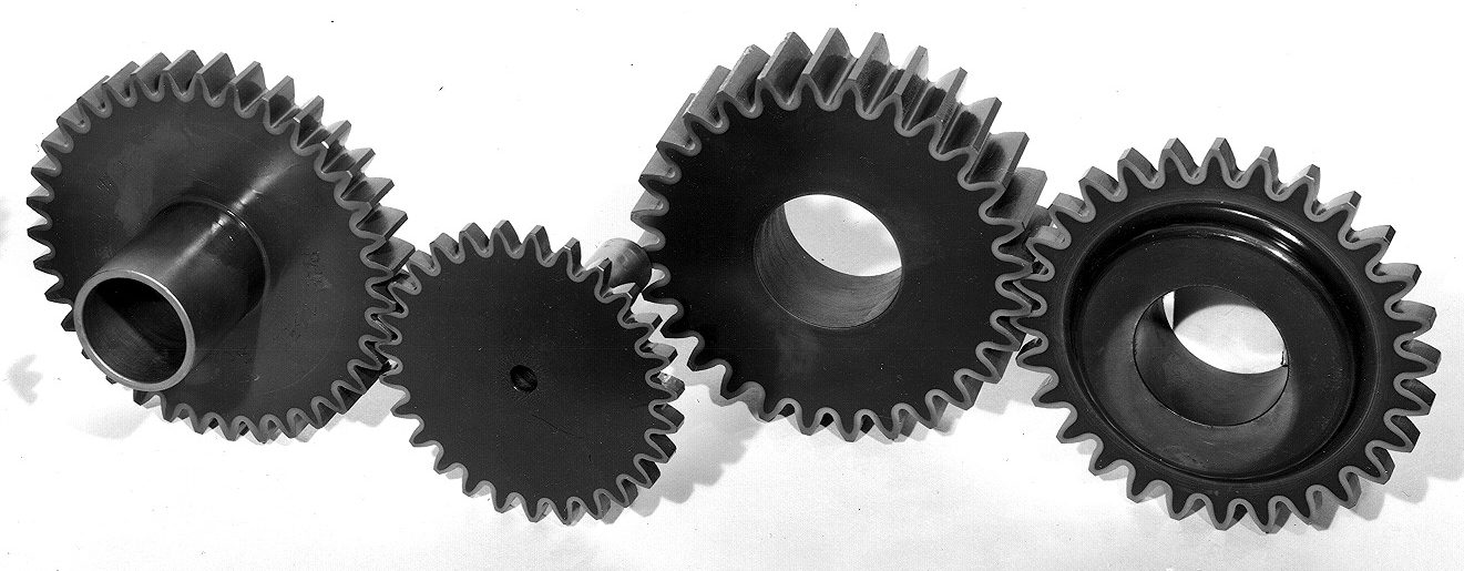
With TSH technology, components are usually through heated, or partial heated (depth of heating needs to be 2-3x deeper than required harden depth) and then rapidly quenched. The hardened depth is mainly controlled by the steel’s chemical composition. Even though components made from TSH steels are often through-heated, their limited hardenability allows for obtaining crisp hardness case depth with a well-controlled hardness pattern having minimum case hardness deviations, even when hardening complex-shaped parts (Figure 7 and Figure 8).
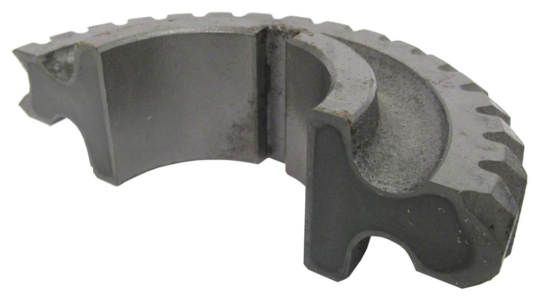
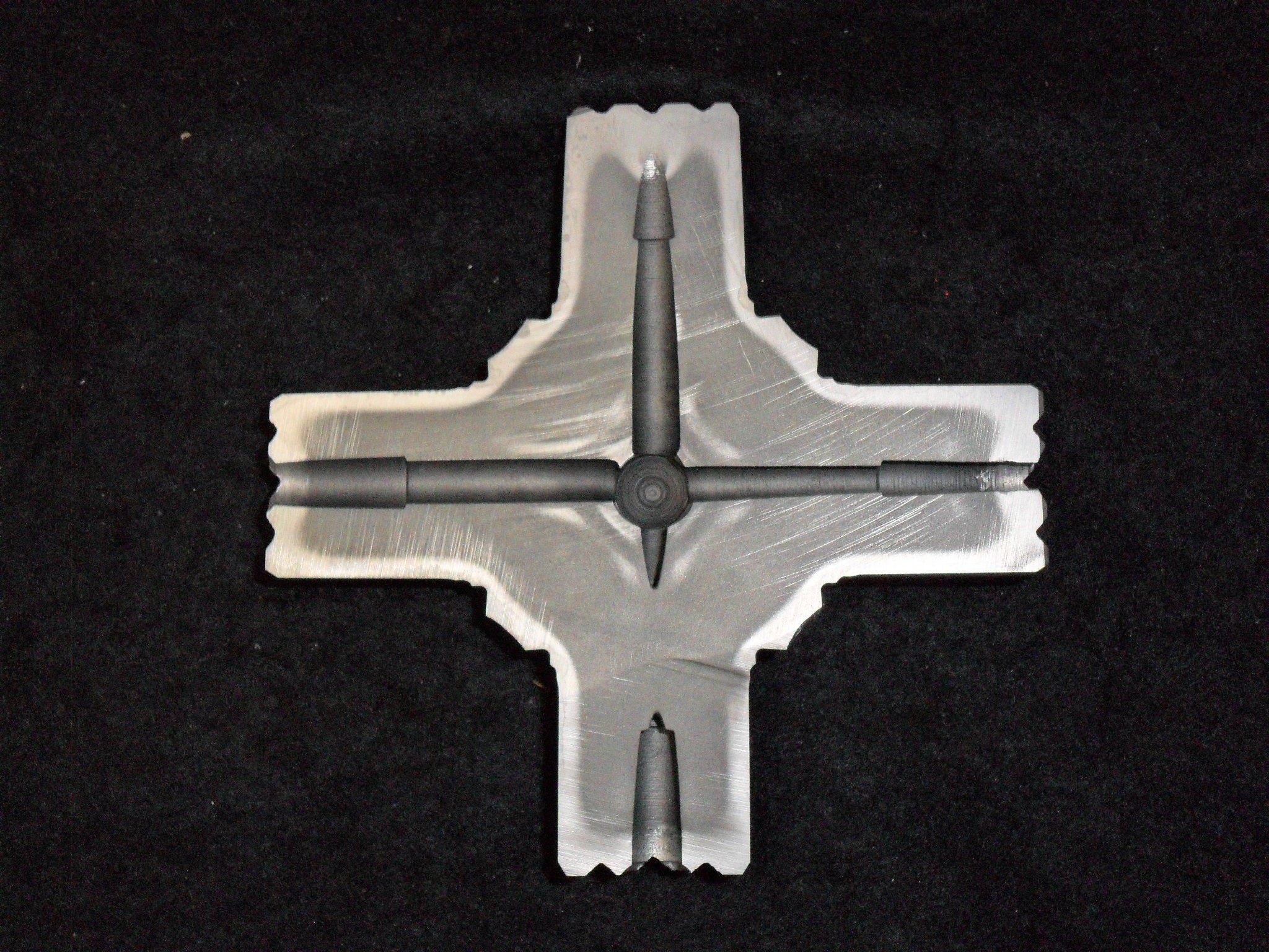
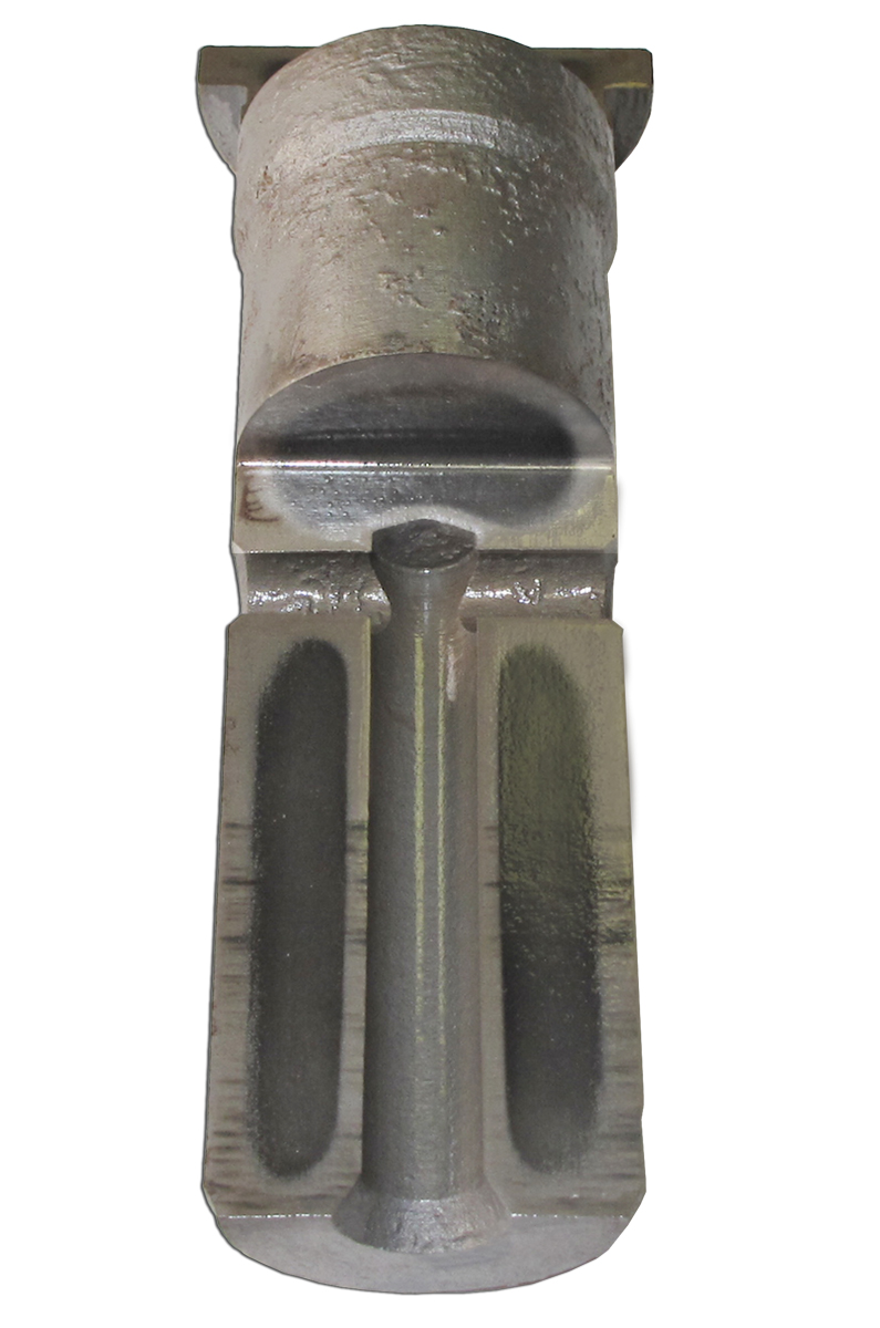
In the past, it was practically impossible to induction harden the components shown in Figure 6, Figure 7 , Figure 8 and Figure 9. Now it is possible to get those impressive uninterrupted hardness patterns by using a simple operation: Through heating those parts using low frequency inverters and water quenching. Notice that spiral bevel pinion (Figure 6) was induction hardened on OD, ID, and teeth region using a single operation having a continuous hardness pattern. The carrier pin (Figure 9) was induction hardened on outside surface (1.25” diameter) and two inside diameters (longitudinal and transversal) using a single operation that also produced un-interrupted case hardness pattern. Inside diameter of longitudinal hole was 0.5“. The inside diameter of the transverse hole was 0.25” [7,8].
Conclusions
Induction heat-treating being environmentally friendly, green, and lean technology is an increasingly popular choice for induction hardening of gears and gear-like components. Recently developed inverters and process know-how further expands its capabilities.
References
- Rudnev, V. and Loveless, D., Handbook of Induction Heating, Marcel Dekker, NY, 2003.
- Doyon, G., Brown, D., Rudnev, V., Andrgea, F., Stilwala, C. and Almeida, E., Induction heating helps to put wind turbines in high gear, Heat Treating Progress, September, 2009, p.55-58.
- Rudnev, V., Spin Hardening of Gears Revisited, Heat Treating Progress, ASM Int., March/April, 2004, p.17-20
- Rudnev, V., Induction hardening of gears and critical components, Part 1, Gear Technology, p 58-63, Sept./Oct. 2008
- Rudnev, V., Induction hardening of gears and critical components, Part 2, Gear Technology, p 47-53, Nov./Dec. 2008
- Rudnev, V., Single-coil dual frequency induction hardening of gears, Heat Treating Progress, ASM International, October, 2009, p 9-11
- Breakthrough contour hardening, ERS Engineering brochure, 2011
- Brayman, S., Kuznetsov, A., Nikitin, S., Binoniemi, B. and Rudnev, V., Contour hardening bevel, hypoid, and pinion gears, Gear Solutions, September, 2011, p. 30-35


 general practice for CQI-9 and AMS2750E")


