


")
The performance of heat-treated steel components is largely dependent on the condition of their surface. Wear and fatigue resistance are examples of design criteria primarily controlled by surface microstructure and mechanical properties. As a result, surface modifying heat treatments such as carburizing, nitriding, and induction hardening are often specified when a component’s design requires a specific set of mechanical properties near the surface. Additionally, post-heat treatment processing such as grinding and hard turning demands consistent near-surface mechanical properties to ensure an optimized process can be achieved. Decarburization is one phenomenon that can occur in improperly controlled heat treatment processes that negatively alters the surface and near-surface mechanical properties of a component. Understanding the fundamentals of decarburization in controlled atmosphere heat treating is imperative to achieving the desired process and product performance.
Fundamentals
Decarburization is the process in which carbon is removed from a material. With respect to heat treatment, this process describes a chemical reaction that occurs on the surface and results in carbon leaving the steel in a gaseous state [1]. If the chemical equilibrium between the carbon in the steel and the carbon in the furnace gases cannot be maintained, decarburization can result. Although decarburization can be used in the manufacturing of materials such as electrical steels, it is generally considered the consequence of an improperly controlled heat-treatment process. The following chemical reactions are involved in maintaining furnace atmosphere equilibrium:
CFe + CO2(g) ↔ 2CO(g) Equation 1
CFe + H2O(g) ↔ CO(g) + H2(g) Equation 2
CFe + 2H2(g) ← CH4(g) Equation 3
It is important to note that it is generally accepted that Equations 1 and 2 are reversible reactions while Equation 3 is not [1]. Equation 1 represents the equilibrium between carbon in the steel (CFe), carbon dioxide gas (CO2(g)), and carbon monoxide gas (CO(g)). Equation 2 represents the equilibrium between carbon in the steel (CFe), water vapor (H2O(g)), carbon monoxide gas (CO(g)), and hydrogen gas (H2(g)). Equation 3 is the disassociation of methane gas (CH4(g)) into hydrogen gas, and nascent carbon that can diffuse into the steel under the correct conditions. Causing the equations to proceed from left to right results in decarburizing while the opposite results in carburization. Changing conditions such as furnace temperature, gas flow rate or composition will shift the equilibrium of all three equations.
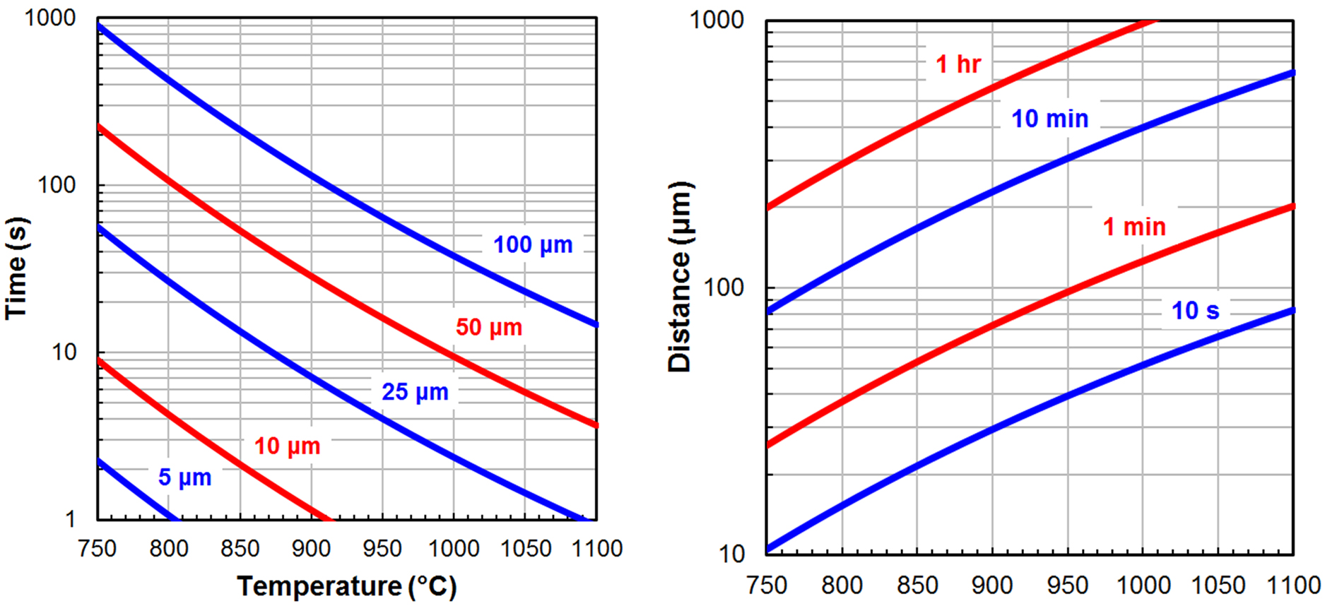
The extent of decarburization possible in a steel heat treatment process can be estimated by calculating the carbon diffusion distance using the following two equations.
D = D0 ⋅ e(-Q/RT) Equation 4
t = d2/6D Equation 5
Equation 4 is the diffusivity (D), which is calculated using the pre-exponential constant (D0, 0.20 x 10⁻⁴ m/s2 for carbon in austenite [2]), the activation energy (Q, 138.2 kJ/mol for carbon in austenite [2]), gas constant (R, 8.314 J/mol·K), and temperature (T) in Kelvin. Equation 5 is an approximation of the diffusion time (t) in seconds for a single carbon atom to travel a specific distance (d) in micrometers [3].
Figure 1 shows Equations 4 and 5 solved for carbon in austenite over a broad range of temperatures, times, and diffusion distances using consistent units. It is important to emphasize the two plots are approximations that do not account for the statistical nature of diffusion as well as common phenomena such as grain boundary and pipe diffusion. In addition, the presence of alloying elements such as chromium (Cr), molybdenum (Mo), vanadium (V), and tungsten (W) have been shown to significantly decrease decarburization rates [4]. However, this approach allows a process engineer to quickly determine what is feasible and what is not.
Characterization and Classification
Decarburization is typically characterized using the terms: complete, partial and effective decarburization. Complete decarburization is also known as “free ferrite” because a ferrite layer transforms at the surface in the absence of carbon. In medium- and high-carbon steels, this layer is readily identifiable due to its white-etching response. In low-carbon steels, this is more difficult to identify due to the high fraction of ferrite that can exist in the microstructure as a result of the cooling rate (e.g., low-carbon pearlitic steels). Partial decarburization is essentially the entire region containing a measurable carbon gradient that is not exhibiting “free ferrite.” This region is often difficult to identify metallographically because microstructure changes occur much more gradually. Effective decarburization is the depth at which any measurable decarburization occurs that results in mechanical properties below the requirements specified for the component. If the mechanical properties of a material are correlated to hardness then the microhardness profile can be used to define the effective decarburization depth.
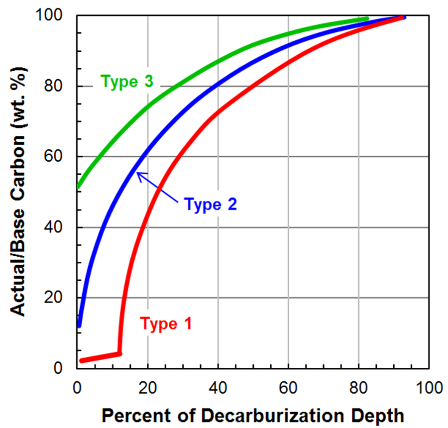
Figure 2 shows three different carbon gradients that can be used to classify decarburization into types. These classifications can be used to select a process necessary to meet a product specification. Type 3 decarburization is defined by the surface carbon content of the steel not dropping below 50 percent of the base steel’s carbon content. Type 2 decarburization is defined by the surface carbon content of the steel dropping below 50 percent of the base steel’s carbon content but not low enough to completely remove all carbon from the surface causing carbon free ferrite to form. Type 1 decarburization is defined by the surface carbon content being low enough for an adequate depth to result in carbon free ferrite to form.
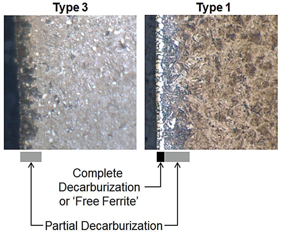
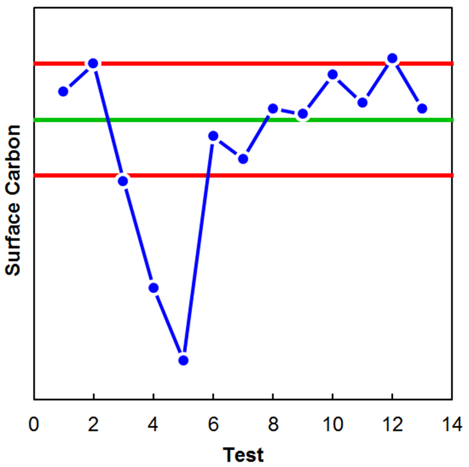
Figure 3 shows an example of optical micrographs of high-carbon steel exhibiting both Type 3 (left) and Type 1 (right) decarburization. The complete decarburization or “free ferrite” region is identified as the white-etching layer at the surface. Partial decarburization is identified as the dark-etching region that is likely upper bainite in these specific conditions. Although the partial decarburization layer may extend deeper into the steel than only the dark etching layer, microhardness traverses would be required to quantify it with any level of precision. In some instances, quantification of decarburization is not required and only a semi-quantitative check is necessary to validate that furnace atmosphere control is being maintained. Figure 4 is an example where a simple surface carbon check using optical emission spectroscopy (OES) was used to verify the process was being maintained. The green line indicates the target process, meanwhile the red lines indicate the acceptable surface carbon range. The drop in surface carbon observed during tests 3, 4, and 5 was verified to be real via metallography.
Summary
Decarburization is typically the result of inadequate process control. In the case of atmosphere-controlled heat-treatment, the primary contributors to decarburization are carbon dioxide, water vapor, oxygen, and hydrogen. The extent of decarburization possible in a heat-treatment process can be approximated by calculating the diffusion distance of carbon in austenite for the duration and temperatures of interest. In extreme circumstances the surface can be completely decarburized resulting in free ferrite formation. In some instances, a relatively simple surface carbon check via OES can be done to ensure decarburization is being kept in check.
References
- G. Parrish, Carburizing: Microstructures and Properties, ASM International, Materials Park OH, 1999.
- B.C. De Cooman and J.G. Speer, Fundamentals of Steel Product Metallurgy, Association for Iron and Steel Technology, 2011, p.40.
- J.D. Verhoeven, Steel Metallurgy for the Non-Metallurgist, ASM International, Materials Park, OH, 2007.
- ASM Handbook Vol. 4B: Steel Heat Treating Technologies, ASM International, Materials Park, OH, 2014.
- SAE J419, “Methods of Measuring Decarburization,” Jan 2018.


 general practice for CQI-9 and AMS2750E")


