


Whether a component is produced through binder-jet additive manufacturing, metal injection molding, or conventional press and sintering, lubricant removal continues to be one of the most common issues in sintering. As with all technologies, new forming techniques have resulted in the development of new lubricants. The result is the need for even more understanding and process development in lubricant removal. A review of the “old rules of thumb,” current solutions, and where the lubricant removal technology is headed will help to lay out a roadmap for dealing with this issue today and into the future.
Background
There are two common steps to the manufacturing process of powder metal components, shaping the powder into the desired component geometry and sintering the component to develop the desired properties of the material. In each of these steps, the lubricant that is added to the powder is a key consideration. During the forming step, such as compaction, the lubricant provides lubrication when it melts and moves to the surfaces of the die. Lubricant is necessary for the ejection of the compact, prevents cracking of the compact, and improves tool life. Unfortunately, the lubricant that was so necessary in the shaping step must be removed from the powder metal compact before the powder metal particles may sinter together.
The lubricant that coats each particle now acts as a barrier between the particles and may hinder the sintering process. Hence, the lubricant must be removed from the compact in the initial stages of the sintering process. Failure to adequately remove the lubricant may result in a number of problems within the part and the sintering furnace.
The most common type of lubricant used in the conventional powder metal process is Ethylene Bis-Stearamide (EBS), also known as Acrawax-C from Lonza Group. This material is reported to have a melting point of 140°C (284°F) and a boiling point of 260°C (500°F). One may conclude that the lubricant should melt and boil out of the compact early on in the sintering process; however, this is not the case.
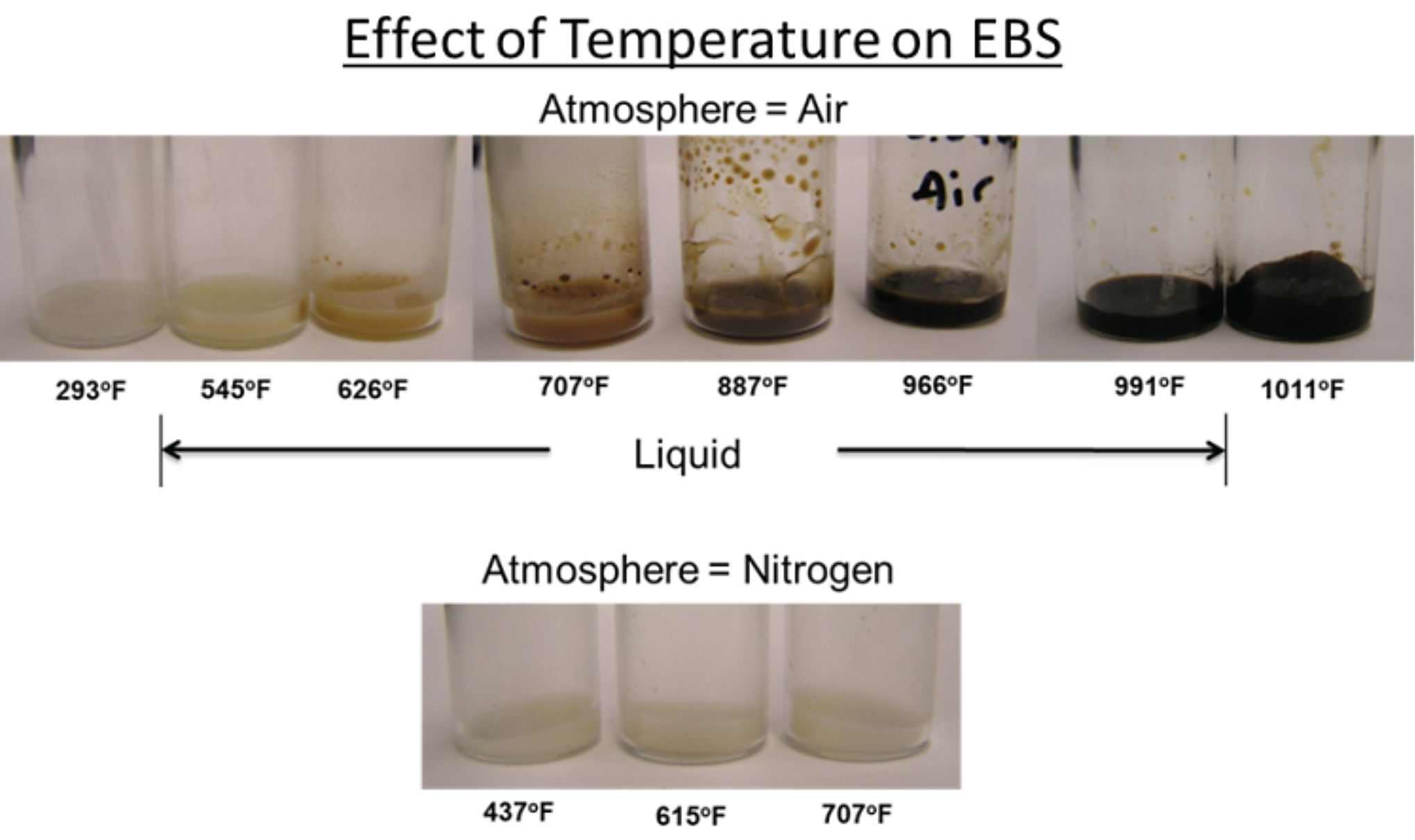
In work by Powell, et. al, EBS was observed as a function of temperature. It can be seen in Figure 2 that the EBS does not boil at 260°C (500°F). In fact, it remains as a liquid to approximately 540°C (1,000°F) and then totally dissociates to carbon and hydrogen. This solid carbon, or soot, that is formed is the root cause of lubricant removal issues in the powder metal process. Varying in degrees of severity, soot can be found on the parts, in the parts, and in the furnace.
Another important observation noted that, once the EBS melts, carbon begins to be present in the liquid as a solid until the entire solution becomes solid carbon. This was explained in a mechanism first proposed in lectures by Levanduski, et. al. of Abbott Furnace Company. (Figure 3)
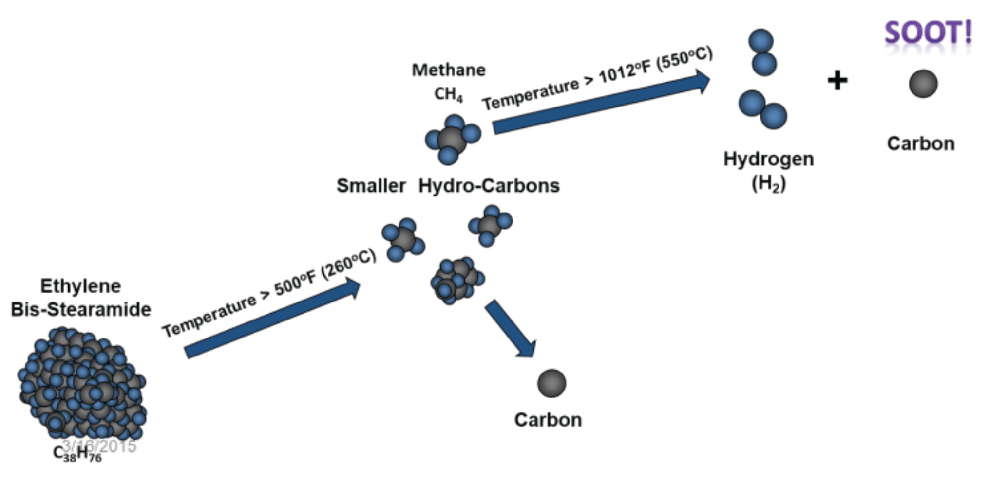
Like most hydrocarbon chains, as EBS is heated, it begins to break down into smaller hydrocarbon chains. It will eventually break down to become the smallest hydrocarbon, methane. Thermodynamically, methane is no longer stable once it reaches approximately 550°C (1,020°F), and it will dissociate into solid carbon and hydrogen. This is supported by the observation of Powell, et. al.
Powell, et. al. also note that the density of the powder metal compact plays a major role in the lubricant removal process. As the compaction technology improves to allow the production of compacts with an as-compacted density that is greater and greater, the time that is needed for the EBS to come out of the compact becomes longer. This forces us to reconsider the long-standing rule of thumb indicating 20 minutes was adequate for the removal of EBS. (Figure 4)
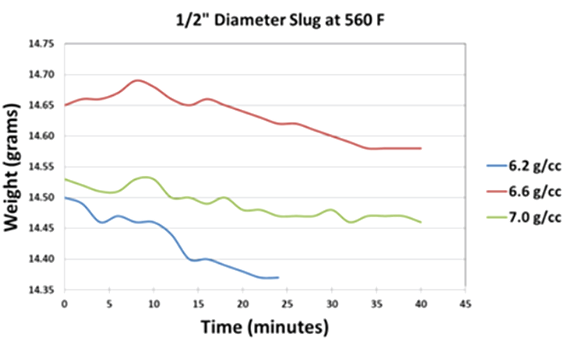
Here, we see the rule of thumb would work well for lower-density compacts that were common of the past; however, this is no longer a valid rule. The time for the lubricant to come out of the compact, hence the time for the compact to be between the temperatures of 140°C (284°F) and 540°C (1,000°F), must increase with the desire to compact to higher green densities.
Levanduski, et. al. point out one other important step in this mechanism: As the EBS breaks down, it cannot be divided into an even number of methane molecules. The result is carbon being left behind. This explains the presence of the carbon in the liquid of the melting study of Powell, et. al. This also points to another key aspect of the lubricant removal process: The lubricant comes out of the compact as a liquid and then boils to form a vapor; however, even though all of the liquid lubricant may be removed, there will still be solid carbon behind as the EBS dissociates.
Lubricant Removal Aids and Equipment
Over the years, a number of devices and processing aids have been developed to aid in the removal of the lubricant and address the presence of carbon. The first sintering furnaces were single box designs where the compact would be preheated and the lubricant removal was to take place in the front of the heated box. It was then determined that two heated boxes on the furnace helping with the lubricant removal would allow for the rule of the thumb of 20 minutes in the first heated box to be maintained; however, as the density of the compacts increased and the sintering loads increased, this was not enough to address all of the lubricant removal issues.
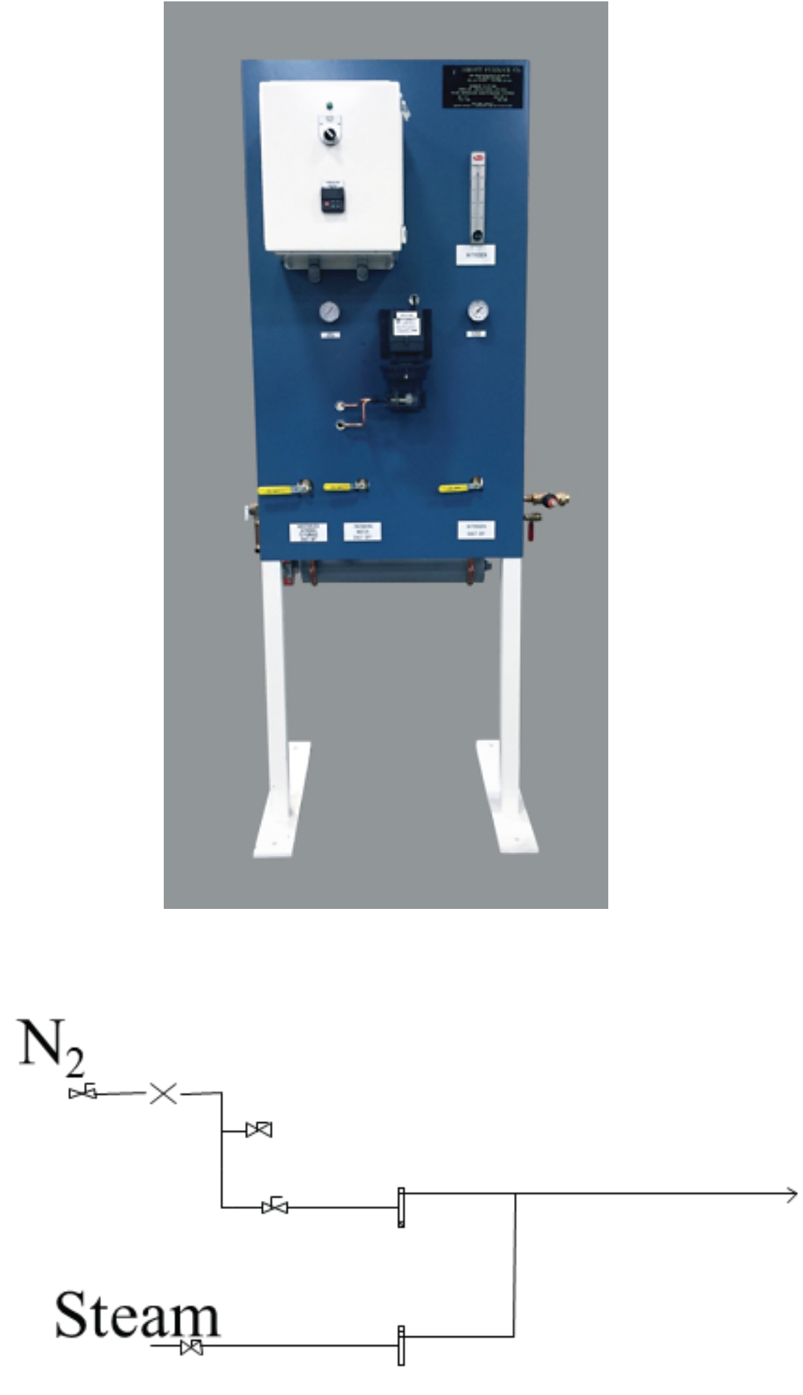
The bubbler was the first device added to furnaces to help in the removal of lubricants and address sooting. (Figure 5)
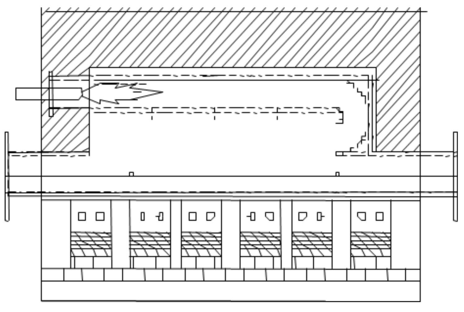
The concept was to bubble nitrogen gas through water. The nitrogen would pick up moisture and carry it into the pre-heat section of the furnace. The injection location was typically placed two-thirds of the way into the pre-heat section. This coincided with the location where most products would reach approximately 650°C (1,200°F) because it could be seen in the furnace that this was the location where the soot began to form and collect. (Figure 6)
To further the capability of the bubbler, the water was then heated to accelerate the formation of water vapor that formed and was carried into the furnace.
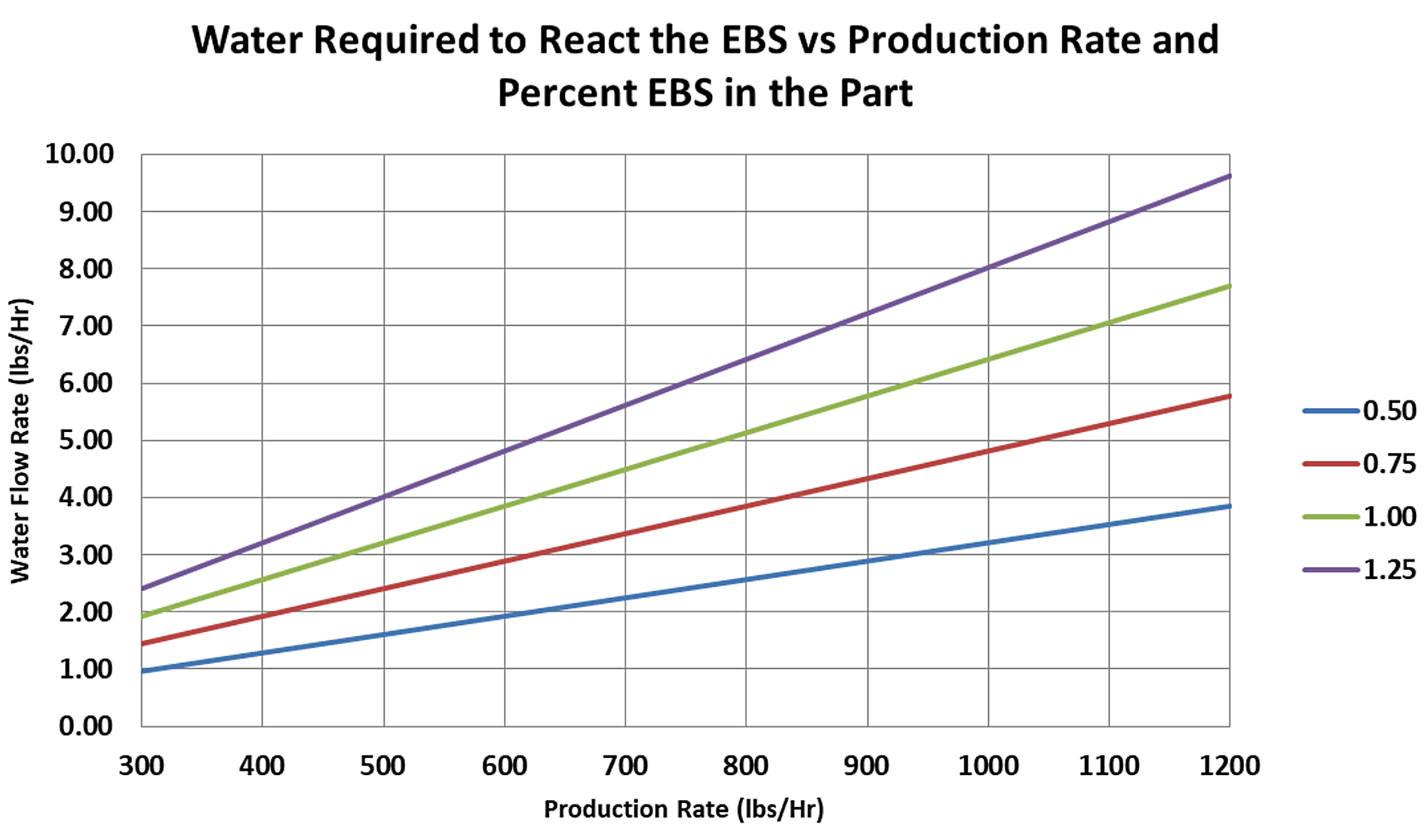
The degree of control of the bubble is limited because one only has the water temperature and nitrogen flow rate as adjustment variables; however, bubblers perform well for small to medium parts and production rates. They are capable of producing up to approximately 5 lbs/hr of water vapor. (Figure 7)
Unfortunately, the variability in the performance of the bubbler increases at the higher flow rates because the large amount of the nitrogen can often cause the water bath to become unstable and liquid water to be picked up by the gas. This liquid form of the water then causes surges in the actual amount of moisture being introduced into the furnace.
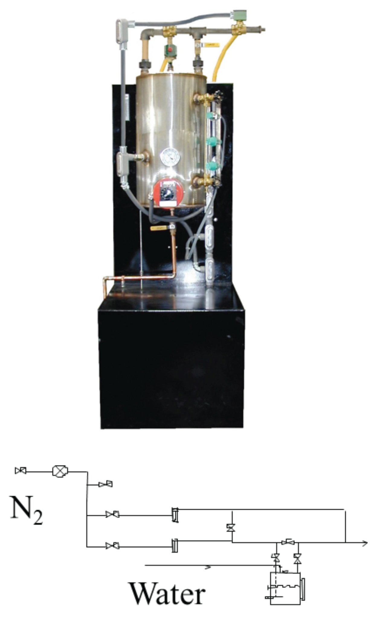
To address the control issues of the bubbler, a device was developed where water is dropped into a heater to form steam. The steam is then carried by a flow of nitrogen into the same injection location of the furnace as the bubbler. These systems are called F.A.S.T. systems. (Figure 8)
Because the control variable is now the amount of water introduced to the heater, the degree of control is much better. The limiting factor is the heater size; hence, the amount of water vapor that can be produced. F.A.S.T. systems are typically limited to approximately 2.5 lbs/hr of water vapor. The systems work well for low production rates and small parts with less lubricant.
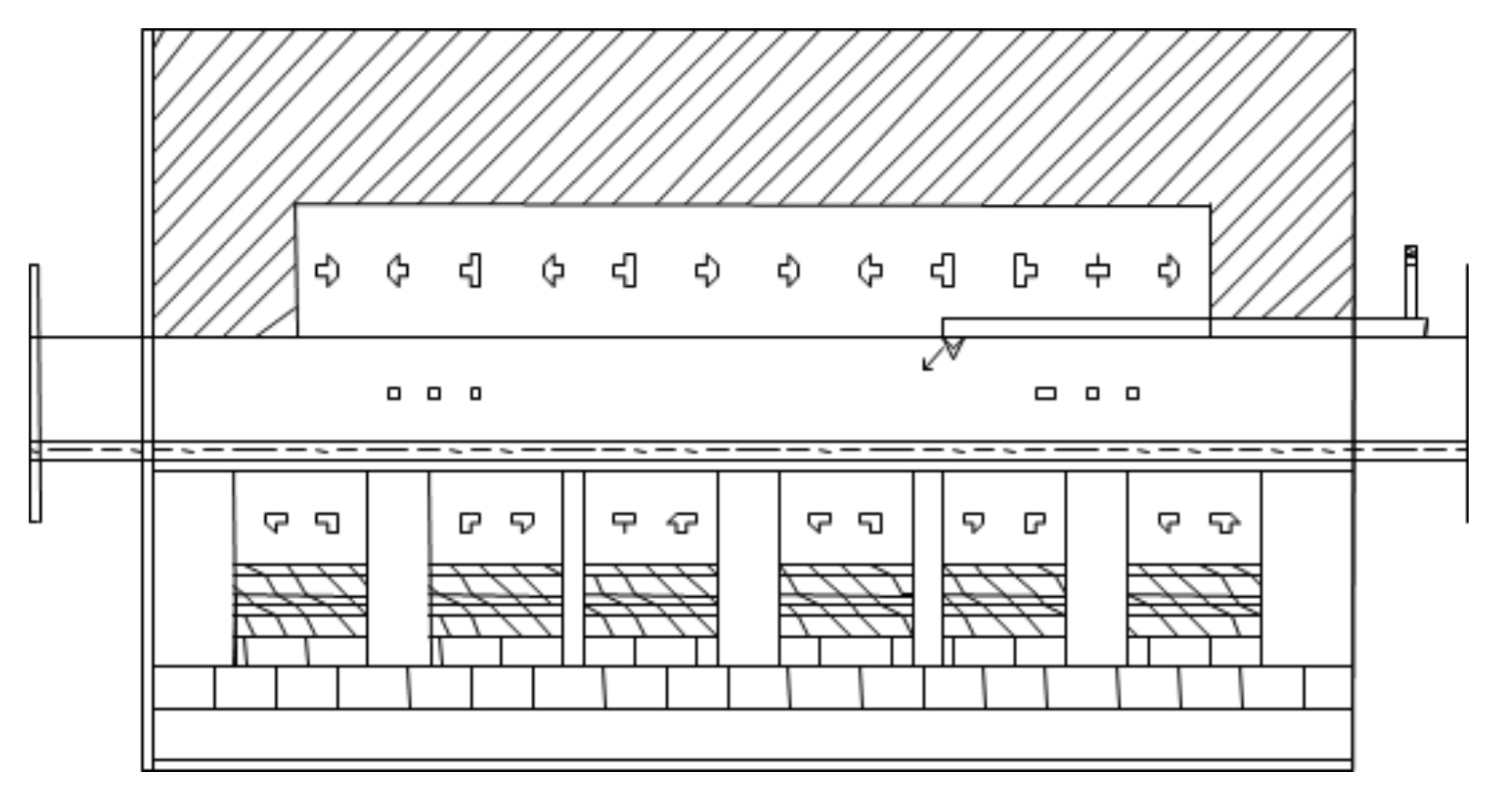
For production rates and large parts that require more water vapor to react with the lubricant, systems were developed that used a gas burner to produce the atmosphere. The air-to-fuel ratio of the burner is adjusted to produce the moisture containing atmosphere used to help in the lubricant removal process. A common example of this technology is a Q.D.P. (Figure 9)
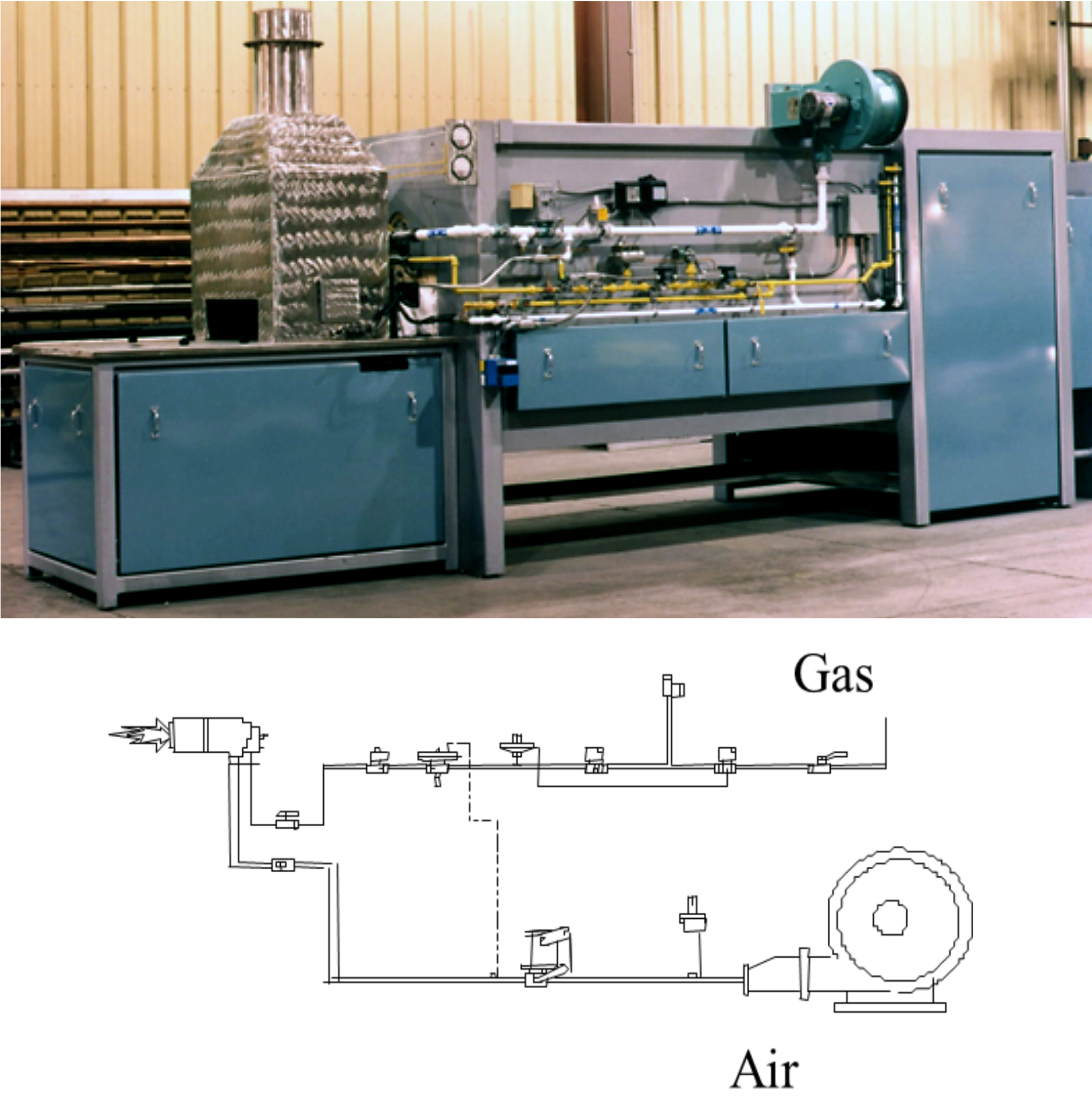
The burner gas is produced in a chamber above the product as it enters. The gas is introduced to the product at the same location of the pre-heating step of the process as the other methods, approximately 650°C (1,200°F). (Figure 10)
Limited only by the size of the burner that is selected, the amount of water vapor that this type of system can produce is substantially larger than other systems. Due to the very large amount of moisture that is produced even when the burner is turned down to low fire, this system does not work well for small parts and light production loads.
These loads do not carry enough carbon-producing lubricant to react with the large amount of moisture produced. The result is an oxidation of the parts that is evident by frosting and decarburization.
The system is controlled by a thermocouple located in the upper combustion chamber. Since the burner produces heat while producing the atmosphere, the amount of moisture is directly influenced by the temperature of the chamber. This is a source of variability.
Another significant drawback to this type of system is the maintenance of the system. Burner performance will change over time. This requires a person knowledgeable in burner adjustment to routinely maintain the system.
Recognizing that the time to remove that lubricant from the compact continues to increase, the preheat sections of the furnace have continued to become longer, and technology has been developed to increase the time the compact is in the optimal temperature range for lubricant removal. One of these, referred to as a Zone 0, is a simple addition of an insulated neck to the preheat section of the furnace. The warm gasses exiting the furnace pass over the incoming components preheat them and help to start the lubricant to melt sooner. (Figure 11)
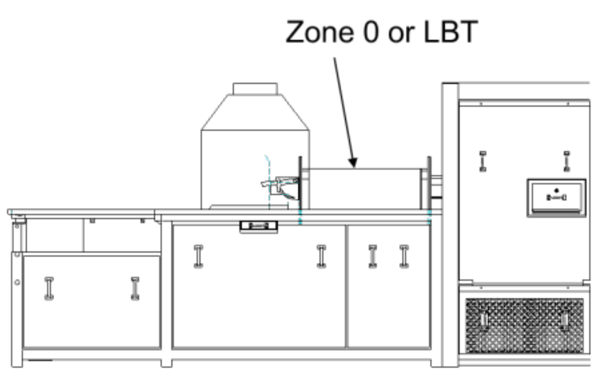
A further addition to this simple approach is to add the ability to inject heated air into the Zone 0. The air reacts with the excess combustible of the furnace atmosphere to produce heat. This addition to the system is called an L.B.T.
Although the Zone 0 and the L.B.T. both help to increase the time for lubricant removal, neither technology provides a means to deal with the carbon produced during the break-down of the hydrocarbon chain.
The Vulcan
The lack of control is the underlying drawback to all of the technologies that have been developed to date. The temperature, time, sintering atmosphere composition, and moisture to aid in reacting carbon are often directly connected or limited in the degree of their control.
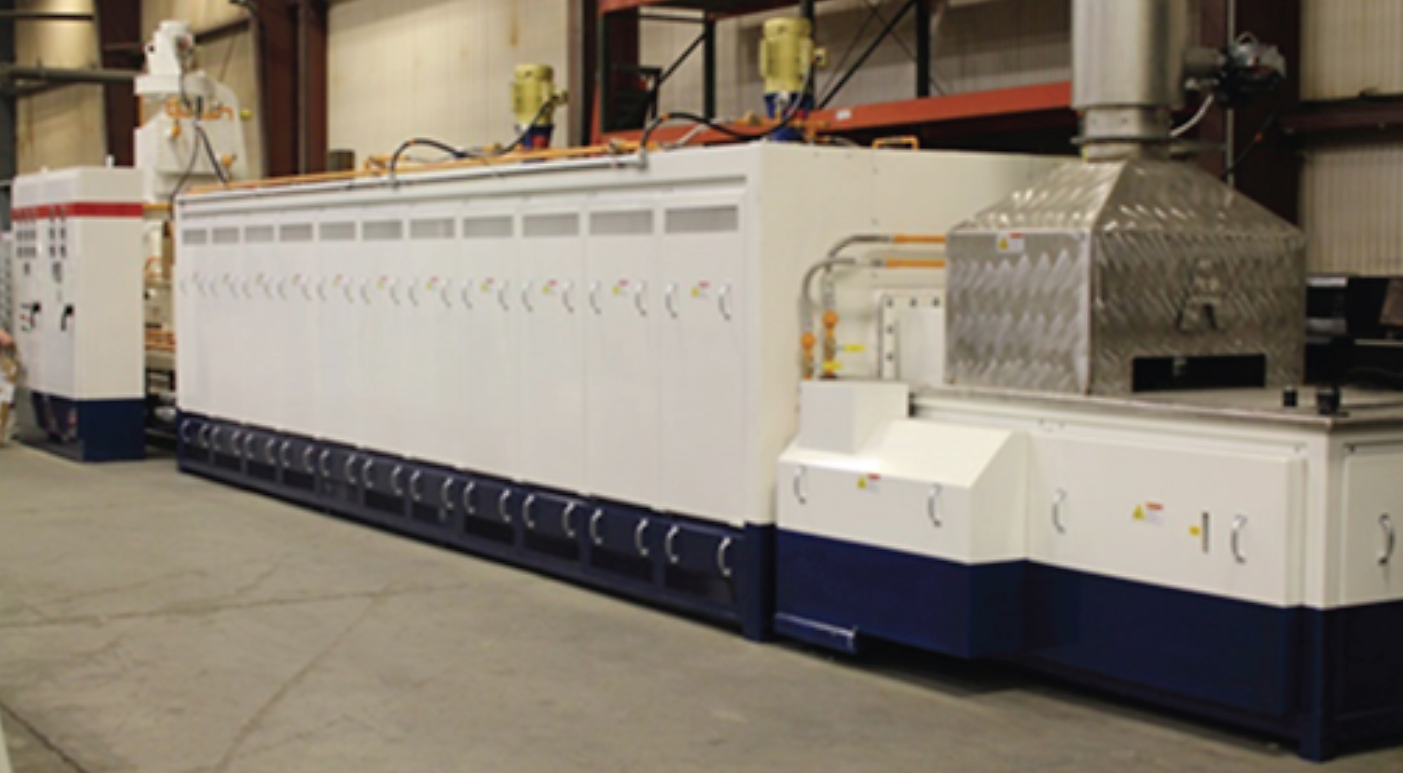
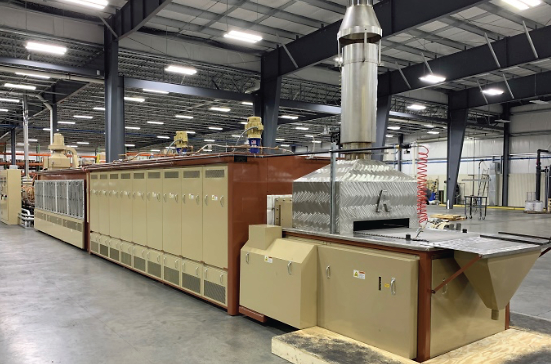
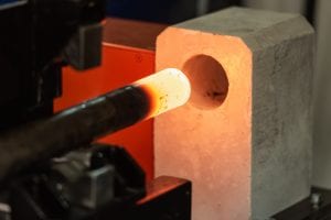
A recent development has been made that focuses on the need for better and independent process control. This system is called the Vulcan. It is a direct replacement for existing pre-heat box technologies. (Figures 1, 12a)
Because the optimal temperature range for lubricant removal is between 140°C (284°F) and 540°C (1,000°F), heating through radiation, as is used in conventional furnaces, is not effective. The Vulcan uses convective heating with variable speed fans to provide independent control of the heating rate and temperature profile of the compact. (Figure 12b)
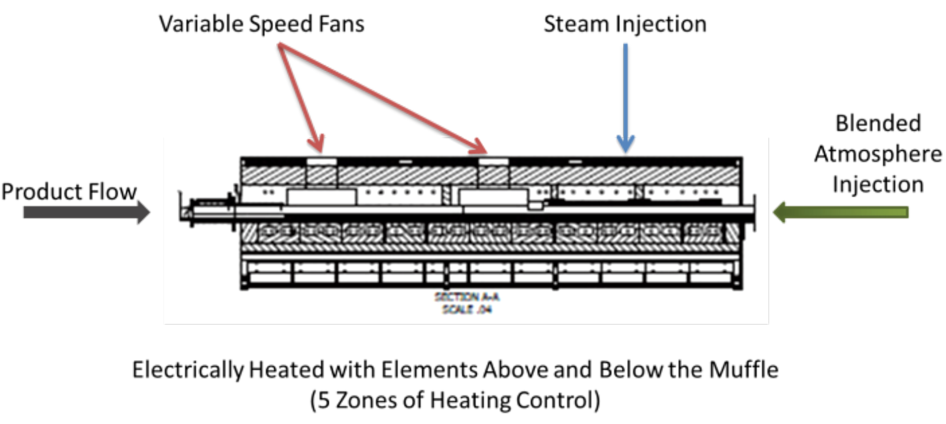
The time in the optimal temperature range is controlled to 540°C (1,000°F) or less by the length of the system and the heating in each zone. This time is adjustable to match the incoming density of the compact, leaving the rule of thumb behind.
The moisture is also independent of all of the other variables. With the ability to produce from 0 to 12 lbs/hr of steam, the flow can be adjusted to provide as much or as little moisture needed to react with the carbon during the break-down of the EBS. This gives the system the ability to process small parts and loads as well as large parts and heavy loads in the same system.
Combining the understanding of lubricant removal with the knowledge of atmosphere control and heat has produced a system that has shown to function at an optimal level for a wide range of production levels and part sizes. Weight loss studies have shown 100 percent lubricant removal for Interlube E and EBS without oxidizing or decarburizing the compact.
References
- Edward Levanduski and Stephen L. Feldbauer, Ph.D., Observations in Lubricant Removal, Presentation, Special Interest Session, PowderMet 2010, Fort Lauderdale, FL., June 2010
- Robert Powell, Craig Stringer, Ph.D. and Stephen L. Feldbauer, Ph.D., “Lubricant Transport within a Powder Metal Compact during Pre-Sinter”, PowderMet 2013, Chicago, IL, June 2013.


 general practice for CQI-9 and AMS2750E")


