


Bending fatigue and contact fatigue performance can be improved by the presence of residual compressive surface stresses [1-2]. Many processes can induce these compressive residual stresses, including carburizing and quenching, induction hardening, and nitriding [3]. However, choosing the proper process, or processes, can be intimidating given all of the available processes currently being used to induce surface compressive stresses in steel components. While the residual stress profile is an important outcome of any hardening process, the resulting distortion must also be considered. Generally, distortion must be corrected, and as such, will reduce the residual compressive surface stresses if shape correction, such as straightening or machining, is performed. This is where heat-treatment simulation software, such as DANTE, can be used to evaluate several processes and determine the optimum with respect to residual stress and distortion for a given part geometry.
This article will use the heat-treatment simulation software DANTE to explore several processes and their effect on distortion and residual stress of a bevel gear. Figure 1 shows the CAD model of the bevel gear used. The gear has an outer diameter of 205mm, a bore diameter of 37.6mm, an axial length of 94.1mm, and 40 teeth. The processes and materials examined will be gas carburization/oil quenching and low-pressure carburization/high-pressure gas quenching of AISI 4320, and induction heating/spray quenching of AISI 4340. Assuming symmetric boundary conditions, only a single tooth is modeled. Figure 2(A) shows the CAD model of the single tooth used in the study, Figure 2(B) shows the single-tooth model meshed for finite element analysis (FEA), and Figure 2(C) shows a section view of the tooth, revealing the fine mesh layer near the surface required to properly capture the steep chemical, thermal, stress, and phase transformation gradients which occur near the surface of the component during a quench hardening process.
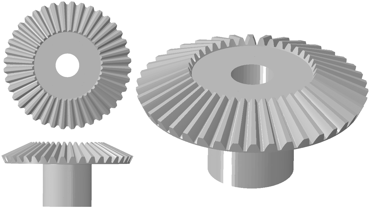
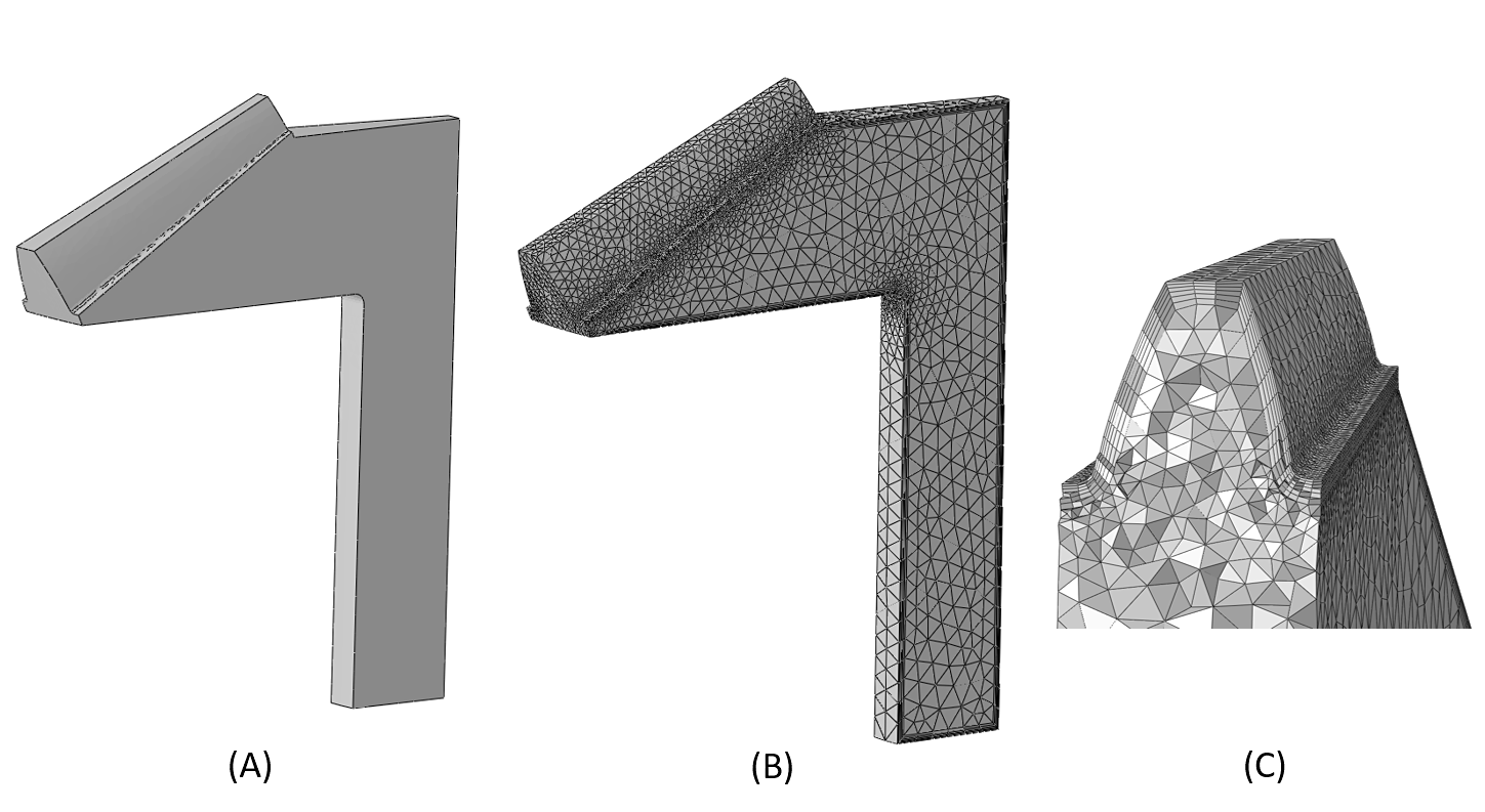
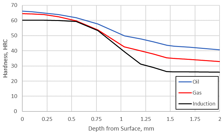
Figure 3 shows the predicted as-quenched hardness profile through the root of the tooth and reveals that the hardness profiles are similar, though not identical. This is due to the differences in carbon concentration, with the gas carburizing process producing the highest hardness due to the slightly higher carbon concentration from the uniform carbon potential applied to the model. In reality, the carbon potential may be reduced in the root area of the tooth due to poor gas circulation, reducing the surface carbon slightly in these areas. Low-pressure carburization can result in reduced carbon on concave surfaces and increased carbon on convex surfaces due to differences in surface area but can also suffer from poor gas circulation in the root area. The induction process produces the lowest hardness as a result of the 0.4 percent base carbon resident on the surface, whereas the carburized gears have surface carbon concentrations between 0.7 percent and 0.8 percent. For the application, all surface hardness values are deemed adequate and within specification. Since all processes produce acceptable hardness profiles, the residual stress profiles should be examined to ensure all three processes produce similar stress profiles, in terms of depth and magnitude. A tempering step would also need to be performed to stabilize the martensite but would only reduce the hardness and residual stress slightly and is not needed for this comparison.
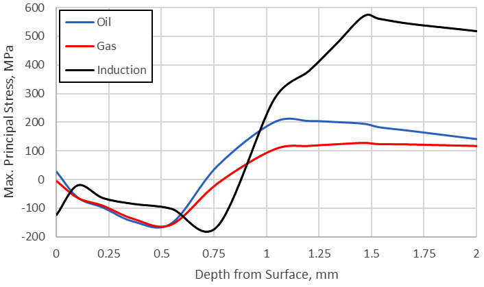
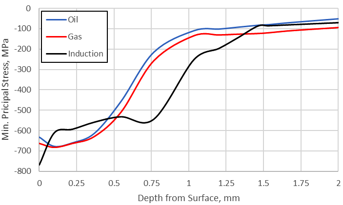
While the hardness is required for the gear to have the required strength, the residual stress in the root-fillet area is of the upmost importance when discussing bending fatigue performance. Any compressive residual stress will, in effect, offset the load experienced in the root-fillet of the tooth, effectively lowering the actual stress seen at the root-fillet of the tooth and improving bending fatigue performance. Figure 4 shows the predicted Maximum Principal stress profile plot through the root-fillet of the tooth. Figure 5 shows the predicted Minimum Principal stress profile through the root of the tooth. As can be seen in Figure 4, The Maximum Principal stress is approximately equivalent through the case for all three processes, but the induction hardening process generates a high tensile stress under the surface. The high stress may cause cracking if any type of defect is present in that location, creating a stress concentration. The higher tensile stress in the induction-hardened tooth is a result of the deeper compressive stresses and the sharp transition from transformation products to the base microstructure.
Although the surface hardness and residual stress are extremely important, the final distortion is also critical since any distortion may require post-heat treatment finishing operations. These finishing operations will alter the hardness and residual stress profiles. Figure 6 compares the predicted deformation of the gear in the axial direction for the three processes. The original shape of the mesh is overlaid to help with visualizing the amount of distortion. The distorted shape has also been magnified 25X to help show the distortion better. As can be seen in Figure 6, induction heating and spray quenching produces the least amount of distortion, approximately 15µm of deflection and almost no taper. This is due to only the surface layer being heated and transformed to austenite, and then to martensite. For this geometry, oil quenching caused the most distortion, approximately 200µm of deflection and 100µm of taper, though this is not always the case. Distortion is dependent on cooling uniformity, which is dependent on cooling rate and geometry [4]. This also helps explain the small distortion from induction hardening; since there is only a thin layer heated, the uniformity during quenching is easier to maintain, regardless of geometry. However, induction tooling comes at a great cost and must be justified. High-pressure gas quenching also comes with a high capital investment. So, even though these two processes produce less distortion than oil quenching, and as such will require fewer post-heat treatment finishing operations to correct the distortion, they come at an increased cost.

In conclusion, using heat treatment simulation software, such as DANTE, can be a powerful tool when determining the correct process for a particular component. Modeling can also be used to optimize a process for a given part geometry. For example, the process timing, with respect to heating rates and dwell times, may be able to be modified to reduce the high tensile stress in the induction-hardened gear. A different heat transfer coefficient in the oil quench, realized by changing the quench oil, could possibly reduce the distortion of the tooth during oil quenching. While there is no clear answer as to which process should be chosen, this will be dependent on application and specifications, heat-treatment simulation modeling can help designers understand how the distortion will affect fatigue performance by evaluating the residual stress profile and comparing it to the amount of material which must be removed due to distortion.
References
- A.M. Freborg et al., “Bending Fatigue Strength Improvement of Carburized Aerospace Gears,” AHS Technical Paper, May 2006.
- Zhichao Li et al., “Modeling the Effect of Carburization and Quenching on the Development of Residual Stresses and Bending Fatigue Resistance of Steel Gears,” Journal of Materials Engineering and Performance, Vol. 22(3), 2013, p 664 – 672.
- T. Ericsson, “Residual Stresses Caused by Thermal and Thermochemical Treatments,” Advances in Surface Treatments Vol. 4, 1987, p 87 – 113.
- Justin Sims, Zhichao (Charlie) Li, and B. Lynn Ferguson, “Causes of Distortion during High Pressure Gas Quenching Process of Steel Parts,” Proceedings of 30th ASM HTS Conference, Detroit, MI, October 2019.


 general practice for CQI-9 and AMS2750E")


