


The invention of the oxygen probe in the 1980s solved one of heat treatment’s fundamental problems: inexpensive, precise, and responsive carbon control. However, every technological improvement has its own collection of issues, and oxygen probes are no different. They require additional verification of their reliability and accuracy to ensure the heat treater can take advantage of their precision.
In the simplest terms, an oxygen probe consists of two sensors: a thermocouple, usually Type R or S (or, more recently, K) — and a closed-end zirconia tube. The exterior surface of the tube is exposed to the furnace atmosphere; the interior is exposed to normal air. The transport of oxygen from the air side to the furnace side creates a voltage potential. The temperature and oxygen voltage potential are transmitted to a controller, which converts the signals to a “carbon potential” — the measure of the ability of a furnace environment containing active carbon to alter or maintain, under prescribed conditions, the carbon content of the steel [1].
Conversion of the signals from an oxygen probe to a carbon potential relies on two assumptions. First, the air side of the probe is always assumed to be P02 = 21%. Second, the CO content of the furnace atmosphere is assumed to be 20 percent. Both assumptions are reasonable in a properly functioning probe in an endothermic atmosphere. In nitrogen methanol systems, the latter assumption should be verified and corrected as needed.
But despite their convenience, oxygen probes have one disadvantage — they can drift over time. So, while they control the furnace second by second, they may not be consistent week to week. This long-term instability necessitates a system of verification or “backup” testing to ensure that the probe is reading correctly or, if it is not, to provide for a mechanism to adjust the probe’s signal. There are a variety of methods available to accomplish this. The most common are discussed in the following overview.
Verification Methods
Shim Stock
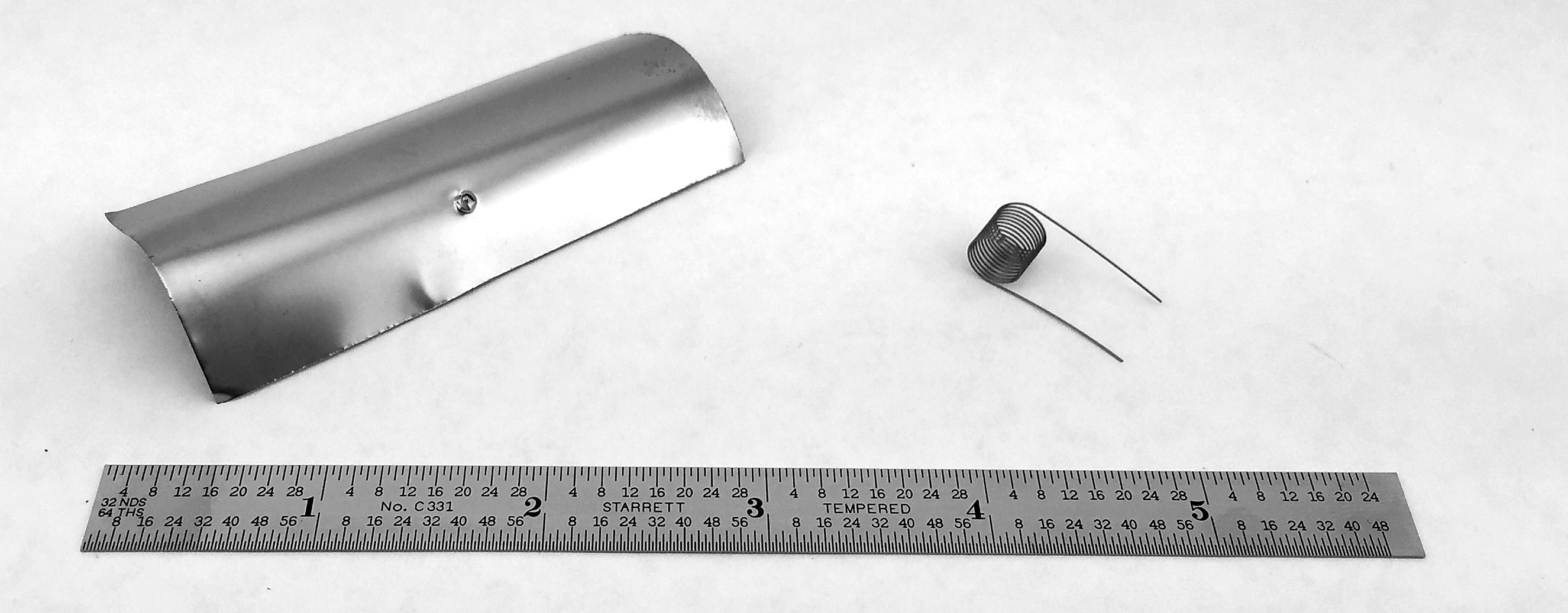
The oldest — and to many, the most definitive — test is the shim stock (or foil) test. In this test, a thin piece of low-carbon steel is inserted into the furnace atmosphere through a port for a period of time sufficient to allow the shim to through-carburize and reach equilibrium with the atmosphere. The shim is then removed, and the amount of carbon in the shim is determined through weight analysis or combustion analysis.
At first glance, shim testing appears to be simple and straightforward. However, the details of the test — such as port and insertion rod design, test duration, test sequence, sample cleanliness, operator technique, scale calibration (in the case of the weight method), or combustion analyzer calibration — can lead to a significant amount of variation.
Once the support infrastructure and appropriate procedures are in place, the shim test is the most direct measure of the furnace atmosphere’s carbon potential because it returns a direct “%C” value of the carbon in the steel. The other verification techniques discussed below are not as direct.
Electrical Resistance
Akin to the shims method is the electrical resistance method. Thin springs are inserted into the furnace and allowed to through-carburize, similar to the way a shim would. The coils are then placed in a dedicated test device; their electrical properties are compared against nominal values, and a carbon potential is inferred. While fast and very convenient, resistance methods have the same drawbacks as the shim test.
Dew Point
Dew point testing is perhaps the oldest of the indirect techniques and does just what the name implies — it measures the temperature at which dew (water condensate) forms. The dew point is the measurement of the water content of the furnace atmosphere, which through the chemistry of an endothermic atmosphere, can be used to calculate the carbon potential. Dew pointers are typically small, portable machines that can be taken from furnace to furnace, measuring each furnace as needed.
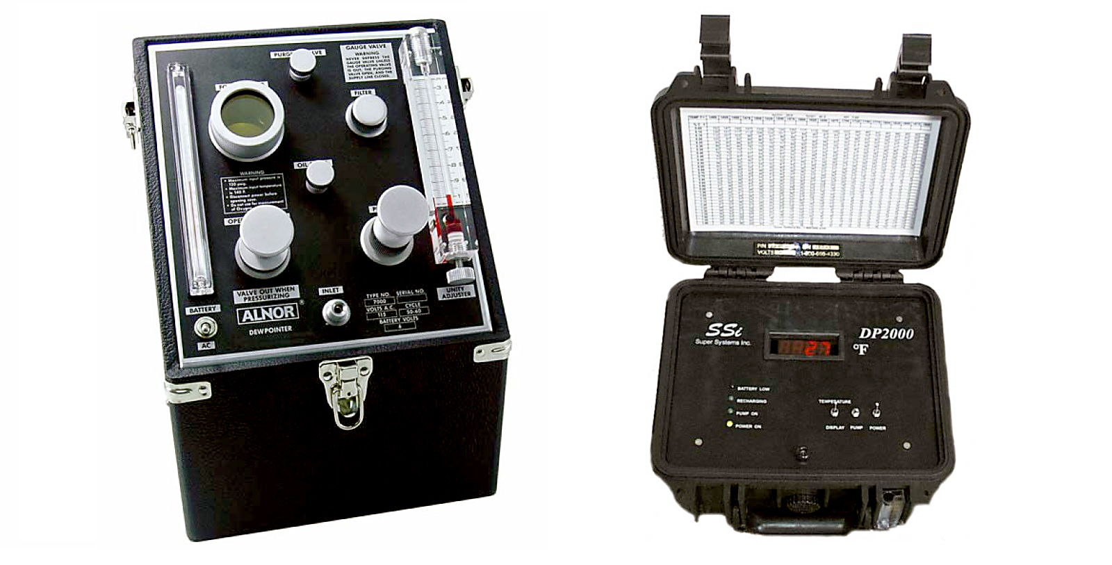
The Alnor fog chamber is considered the classic heat-treating dew point device. The Alnor works by manually pumping a sample of the furnace gas into the device, pressurizing it and then releasing the pressure (and thereby cooling the gas sample) to visually determine if a cloud forms in the device’s chamber. Once the point at which cloud formation occurs is determined, the dew point can be calculated. However, dew point determination is an iterative and time-consuming process.
Although cumbersome to operate, Alnor dew pointers are very precise and work at extremely low dew points — beyond the capability of more modern devices. That said, the Alnor’s accuracy relies on a radioactive isotope to ensure dew formation in the absence of nucleation particles. While not inherently dangerous, this does pose additional safety issues.
At the other technological extreme are the modern sensor-based dew pointers. With these devices, a sample is continuously pumped from the furnace across the sensor. The dew point is determined by the sensor material’s electrical response to the water content of the sample. These devices have the advantage over the Alnor and similar techniques in that the output is essentially immediate and requires no interpretation.
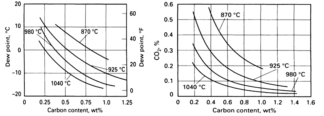
Once the dew point is determined, the next step is converting it to a meaningful carbon potential. Many manufacturers provide a conversion chart with their dew pointers that converts dew point to carbon potential as a function of the furnace temperature.
Dew pointers themselves need calibration, which can be done in-house by purchasing samples of known humidity. As a practical matter, most users would rather avoid managing the calibration trail and prefer to send the devices back to the manufacturer or other qualified supplier for calibration. This, however, creates the need to have multiple devices in rotation so that there is always a dew pointer available for verification of the atmosphere.
Infrared Analysis
Similar in action to dew point testing is non-dispersive infrared (IR) gas analysis. IR gas analysis, sometimes referred to as “three-gas” analysis, continuously pulls a sample from the furnace and determines the CO, CO2 and CH4 content (the “three gases”) of the furnace atmosphere. The CO/CO2 ratio (or simply CO2 in cases where CO is essentially constant) from the IR analyzer can be used to determine the carbon potential with the same calculations used in oxygen probe control. For more sophisticated results, the CH4 component can be factored into the results to take into account its enriching effect. Gas analyzers intended for use in heat treatment often have built-in functionality for calculating and displaying carbon potential.
IR units are available as portable units, similar to dew pointers, or as dedicated assets integrated into the furnace’s carbon control scheme. They correct the carbon potential measurements in real time as the oxygen probe drifts. The dedicated arrangement is generally found in furnaces that use nitrogen methanol systems where the CO content of the atmosphere is variable over time. The integration of the IR analyzer into the control scheme compensates for the deviation from the nominal 20 percent CO value expected in a natural endothermic atmosphere.
Regardless of the method, when it comes to ex situ measurements, care must be taken with the disposal of the gas once it has been analyzed. Endothermic gas is explosive and can build up in control cabinets, vulnerable to an ignition source. Running the exhaust port of the machine back to the burning effluent is a best practice.
Frequency of Verification
Heat treating quality systems have evolved to the point where there are essentially two industry standards for managing heat treatment: CQI-9 and AMS2759. CQI-9 was originally conceived as way of standardizing the automotive approach to heat treatment and is becoming the de facto standard for all non-aerospace industries. AMS2759 is, of course, the aerospace standard for the heat treatment of steel.
The AMS2759 family of standards has no explicit requirements for verification of atmosphere control [4]. The carburizing standard (AMS 2759/7) has very specific testing requirements for verifying the surface carbon — which they refer to as “carbon potential” — of the specific material for each batch, but this arguably is a product test rather than a process control verification [5].
For those systems that don’t continuously verify the probe, CQI-9 requires the minimum of a weekly verification of the probe [4]. However, this may not be sufficient for all processes and furnace types. Some heat treaters conduct shim stock tests with every batch — or multiple times a day, in the case of continuous furnaces.
As a practical matter, it may not be possible to verify the probe over such a range, but effort should be taken to select a combination of temperature and carbon potential that represents a large proportion of the probes’ operating time. Another consideration is the point within the cycle of an asset at which the verification should take place. Conducting the verification at the very beginning of the cycle versus the very end may produce slightly different results, even if the temperature and carbon potential are the same — thereby increasing the potential error in the test.
Verification Tolerance
Again, CQI-9 is the more proscriptive of the two standards, requiring the oxygen probe to be within 0.05 percent of verification method tolerances [6]. For direct-read verification methods, this is straightforward. For dew pointers, a translation chart is required for accuracy, but typically means at an allowable variation of 1°-2°F (0.6°-1.1°C) from aim.
It can be argued that, given all the sources of error in both the oxygen probe and the verification technique, to achieve such tight limits on verifications is overly optimistic and a more open tolerance or other methodology should be explored. However, the standard is the standard, and it is difficult to argue that point with an auditor.
Reaction to and Interpretation of the Data
Once the values of the probe and the verification method are determined, the question becomes, “What next?” In many facilities, the answer may be unclear, as there is often no defined plan for the floor-level operators. As a best practice, there should be a clearly defined reaction plan that provides the operator with guidance on how to correct for out-of-specification test results.
Most carbon controllers have built-in adjustment parameters (often called “process” or “alloy” factors) that allow for correction of the oxygen probe reading based on a verification test. But given that the goal of oxygen probe verification is the increased stability of the process, making constant adjustments to the carbon controller is not a recipe for success. An alternate response is to implement a statistical process control approach in the verification process, along with a robust work instruction and documentation system.
References
- AGMA Standard 923-B05, “Metallurgical Specifications for Steel Gearing,” Alexandria, Virginia: American Gear Manufacturers Association, 2007.
- Dickey-John Corporation, Alnor Dewpointer Manual, Auburn, Illinois: Author, 2005.
- Super Systems Incorporated, DP2000 Portable Dew Point Analyzer Operations Manual, Cincinnati, Ohio: Author, 2017.
- SAE Standard AMS2759, “Heat Treat of Parts, General Requirements,” Warrendale, Pennsylvania: SAE International, 2014.
- SAE Standard AMS2759/7, “Carburizing and Heat Treatment of Carburizing Grade Steel Parts,” Warrendale, Pennsylvania: SAE International, 2014.
- AIAG CQI-9, “Special Process: Heat Treat System Assessment, 3rd Edition,” Southfield, Michigan: Automotive Industry Action Group, 2011.
- J.R. Davis, Surface Hardening of Steels: Understanding the Basics, Materials Park, Ohio: ASM International, 2002.


 general practice for CQI-9 and AMS2750E")


