


Thermocouples are one of the most practical and widely used tools for gathering time/temperature data in thermal processing environments. Ranging from laboratory-scale experiments to full industrial heat-treatment operations, these sensors provide direct insight into how materials respond to heating and cooling cycles. By embedding or attaching thermocouples to components, engineers can capture transient thermal histories that reflect the furnace conditions and the complex system of conduction, convection, and the thermal effects from phase transformations within the material.
One important application of this data is for calibration of boundary conditions such as convective heat transfer coefficients (HTCs) used in computational models to simulate the heat transfer in the process that are otherwise difficult to measure directly.
Despite their utility, thermocouples are not passive measurement tools. Their physical presence, particularly the geometry and placement of the thermocouple wire, can influence the temperatures they record. One notable phenomenon is the “fin heating/cooling” effect, in which the thermocouple wire acts as an extended surface that enhances the local heat transfer. This can distort recorded temperatures and introduce systematic error into both experimental interpretation and subsequent modeling efforts. The present work examines this effect in detail through a combination of finite element modeling and fitting to ultimately quantifying the fin effect and to propose practical mitigation techniques.
Model Setup
To investigate the fin effect, a simplified finite element model was developed. The geometry consists of a cylindrical specimen with a diameter of 25.4mm (1 inch) and a length of 101mm (4 inches). A thermocouple is attached at the mid-height of the cylinder along its axis, with the thermocouple wire modeled as a 2mm diameter (12 AWG) extension normal to the cylinder surface, as shown in Figure 1.
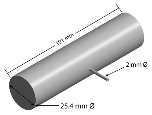
This configuration reflects a common industrial setup in which thermocouples are tack-welded or otherwise affixed to part surfaces during process characterization. The thermal process applied to this model includes a simple heating and quenching process. The specimen is first heated to 900°C under a convective boundary condition corresponding to an HTC of 75 W/m2·K over a period of 1.5 hours. Following this, the part is quenched in a 20°C ambient environment with an HTC of 5,000 W/m2·K for one hour. These conditions are representative of a general heat-treatment operation where large thermal gradients and rapid cooling rates are present.
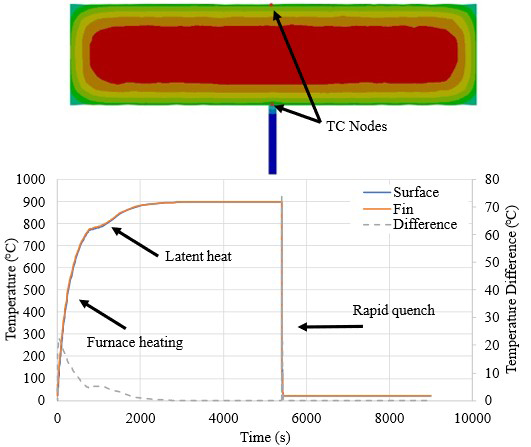
A transient-thermal finite element simulation is used to track temperature evolution throughout the part, with particular attention paid to two locations: the “far surface” (a point on the cylinder unaffected by the thermocouple wire) and the thermocouple attachment point. By comparing these locations, the influence of the thermocouple geometry on measured temperature can be directly assessed. Figure 2 shows an overview of the thermal process and cross-sectional contour of the geometry at about two seconds into the quenching process, with the two nodes highlighted where the time/temperature data was collected. Note the latent heat of phase transformation captured when the part begins to transform to the austenite phase.
Results
The simulation results show the presence and significance of the fin heating/cooling effect. There exists a difference in recorded temperature during the modeled furnace heating process step, but the heat transfer from the part to the environment is slow enough to reduce the fin heating effect to about 20°C difference between the thermocouple measurement and the far surface.
However, during the initial stages of the quench, the thermocouple location experiences accelerated cooling relative to the surrounding material, due to the increased surface area provided by the thermocouple wire, shown in Figure 3. At approximately 1.9 seconds into the quench, the maximum temperature difference between the thermocouple location and the far surface reaches nearly 75°C, at a time when the average part temperature is around 400°C, right around the martensite start temperature for the AISI 4120 steel modeled in this work.
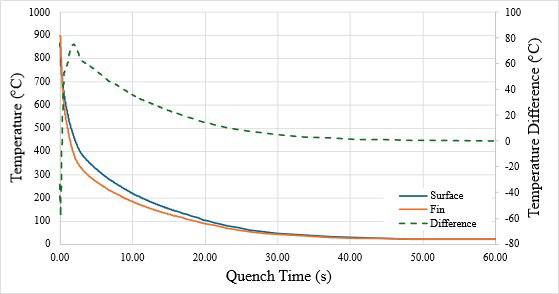
At 20 seconds into the quench, when the part temperature has dropped to approximately 85°C, a temperature difference of about 14°C is still observed. By 30 seconds, this difference falls below 5°C, suggesting that the fin effect becomes less significant as the overall temperature gradient is reduced. While the fin cooling effect is most pronounced during the early stages of rapid cooling, its influence can extend into later stages and should not be neglected, particularly when high accuracy is required.
Heat Transfer Coefficient Fitting
Thermocouple data are often used to back-calculate heat transfer coefficients, which serve as critical boundary conditions in heat-treatment simulations. One common approach is to use inverse or forward finite element methods to fit an HTC value that reproduces the observed time/temperature response. For this example, the commercial tool DANTE HTC Fit is used to perform the analysis. HTC Fit uses a forward finite element method, iteratively running simulations with varying HTC values to minimize the difference between predicted and measured temperature histories.
The inputs for the fitting process include the time/temperature data (in this case, derived from the simulation with a known constant HTC), the ambient temperature (20°C), and a range of HTC values bounded between 1,000 and 9,000 W/m2·K, an initial guess of 4,000 W/m2·K was used, and multiple random iterations (20 loops) were performed to improve the fit. Fitting was conducted at several key time points during the quench, specifically at two, 10, and 20 seconds, to evaluate how the HTC difference varies depending on the portion of the data used.
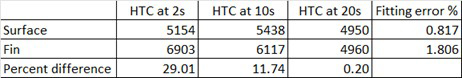
The results reveal a clear and consistent trend that when the thermocouple data influenced by fin cooling are used, the fit HTC values are significantly higher than the true value used in the simulation as shown in Table 1. The fitting results show the presence of the thermocouple wire can increase the HTC fit by nearly 30 percent. This overestimation is because the increased local cooling caused by the wire is interpreted by the fitting algorithm as evidence of a higher convective heat-transfer rate at the surface. In reality, the bulk surface of the part does not experience this elevated HTC and is an artifact of the measurement method.
Such inflated HTC values can lead to inaccurate predictions of temperature evolution, phase transformations, distortion, and residual stress in process models. The error introduced at the measurement stage propagates through the entire modeling workflow.
Discussion and Conclusions
This work demonstrates that the presence of a thermocouple wire can significantly alter the measured response of a component during heat treatment, leading to errors in recorded temperature data. Through finite element modeling of a cylindrical specimen with an attached thermocouple, the fin cooling effect was quantified, revealing peak temperature differences of nearly 75°C early in the quench step.
When these data are used to determine heat transfer coefficients, the resulting values can be overestimated by as much as 30 percent, which has direct consequences for the accuracy of heat-treatment simulations, potentially leading to incorrect predictions. To mitigate the fin cooling effect and improve measurement accuracy, engineers and technicians can position the thermocouple wire along the surface of the part rather than perpendicular to it, where it would not interfere with the flow of the quenchant or bubbles, reducing its effectiveness as a cooling fin.
A small hole can be drilled from the opposite side of the part, and the thermocouple can be inserted to be near the surface without exposing the wire directly to the quenching medium. Another approach is to use thinner thermocouple wires to reduce heat transfer along the wire. Simulations can also be performed to explicitly account for the thermocouple geometry.
Ultimately, accurate thermal characterization requires high-quality data, and a clear understanding of how that data is obtained. By recognizing and addressing the fin cooling effect, engineers can improve both experimental practices and simulation reliability, leading to better-informed decisions in heat-treatment process design and optimization.


 general practice for CQI-9 and AMS2750E")


