


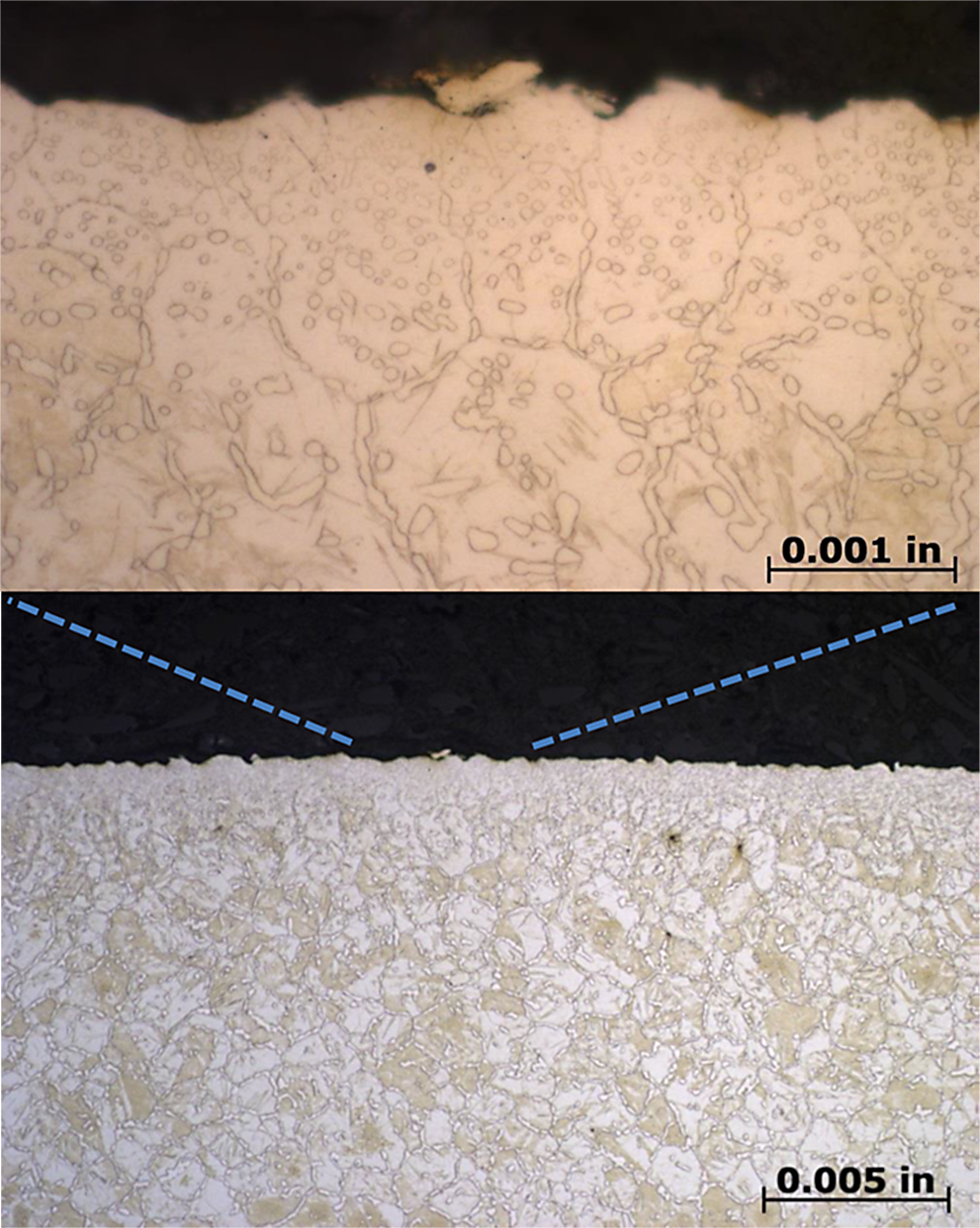
One common goal for a wide range of industries has been to increase power density in shaft and gear components. The steel producing industry responded with high strength steels containing elements such as chromium, vanadium, and molybdenum. While these elements impart a great deal of strength, they also bring the propensity to form carbides during carburizing processes. While gas carburizing has been the main source of carburizing for decades, these types of steels are difficult to gas carburize due to the high amounts of carbides that can form during the process. The formation of these alloy carbides then retards carbon diffusion by reducing the effective carbon gradient.[1] Figure 1 shows excessive carbide formation and networking in Ferrium S53, an extremely difficult to carburize alloy.
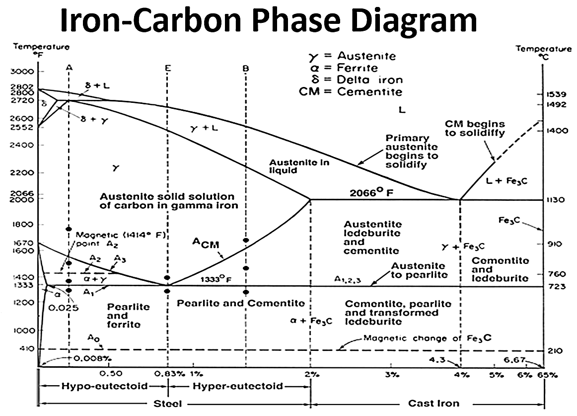
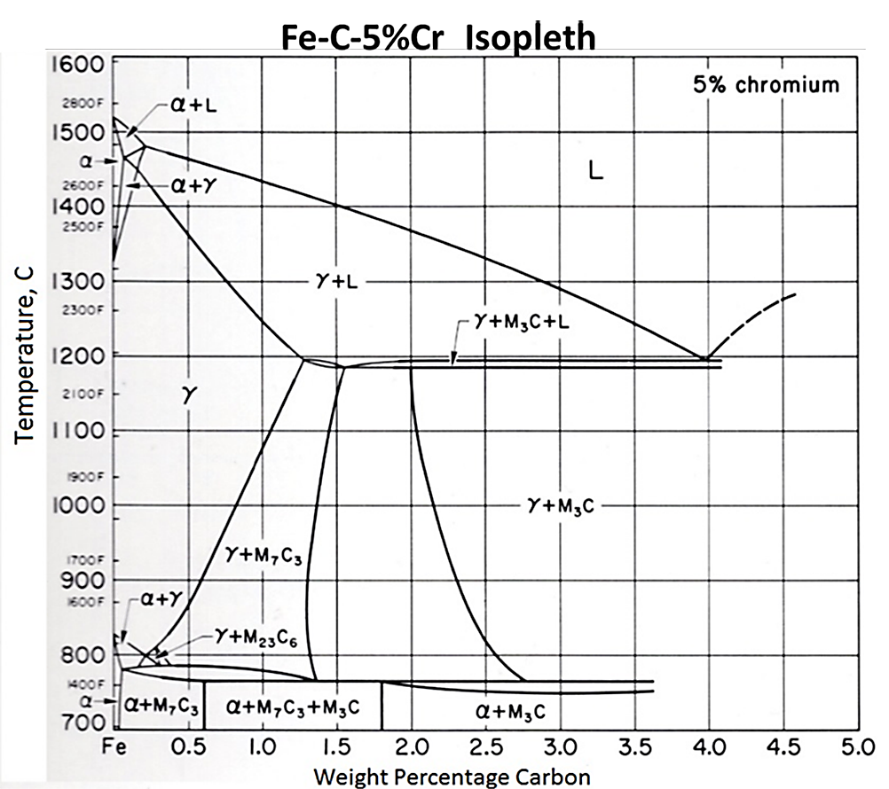
As the amounts of certain alloying elements are increased, the size of the austenite phase field shrinks. This means that less carbon is able to dissolve into the austenite matrix. The carbon that does not dissolve into solution forms carbides. Figure 2 shows a portion of the Fe-C equilibrium phase diagram. Figure 3 shows an isopleth from the Fe-Cr-C ternary phase diagram for 5 percent Cr. At carburizing temperatures, it is possible to dissolve upwards of 1.5 percent carbon in austenite in a Fe-C system. However, for the Fe-Cr-C system with 5 percent chromium, the amount of carbon is reduced to approximately 0.75 percent. For steels with yet higher chromium content, such as Pyrowear 675 with 13 percent chromium, the austenite field is reduced even further, and the formation of carbides at carburizing temperatures is rapid. Understanding when carbides form and how large they grow is extremely important when designing a carburization schedule.
Low pressure carburizing is the perfect solution to the fast forming carbide problem because of the ability to control the atmosphere chemistry quickly; i.e., boost and diffuse steps. During the boost step, where a carbon rich gas is introduced into the vessel, carbon accumulates on the part surface, with some diffusing and some forming carbides. When the carbon carrier gas is removed during the diffuse step, the carbides dissolve and provide an additional carbon source for diffusion into the part. In determining carburizing schedules, carbide formation must be considered for accurate case depth formation. Equations that have been developed over the years, such as the ones shown below, prove ineffective in describing the effect of strong carbide forming elements on the diffusion of carbon. A model must go past simple diffusion and account for the carbide formation and dissolution. These equations are only valid within particular chemistry ranges, as discussed in references [3] for Equation 2, [4] Equation 3, and [5] Equation 4.
Case depth = f ∗ √t Equation 1
D(T,C)=0.47∗exp[-1.6∗C]∗exp[-(37,000-6,600∗C)/R/T] Equation 2
D(T,C)=(0.04+0.08∗C)∗exp[-31,350/R/T] Equation 3
D(T,M,C)=(0.146-0.036∗C∗(1-1.075∗Cr)+Σk1∗M)∗
exp[-(144.3-15.0∗C+0.37∗C2+Σk2∗M)/RkJ/T] Equation 4
where:
T is temperature, °K.
C is weight percentage of carbon.
k1 and k2 are multiplying factors for specific elements.
M is weight percentage of Mn, Si, Ni, Cr, Mo, or Al.
R is the universal gas constant, 1.986 cal/mol/°K.
RkJ is the gas constant expressed as kJ/mol/°K.
Simulation tools, such as DANTE, provide the means to effectively design the boost/diffuse schedules used for the low pressure carburizing process of steels with high carbide forming elements. Simulation can be used to design the duration of the boost steps by predicting the size of the carbides and/or the amount of carbon in carbide form during the boost step. The length of the diffuse step can then be determined by calculating how quickly the carbides dissolve. The two plots show the difference between properly defined boost steps, Figure 4, and a schedule in which the boost steps are too long, Figure 5. Both schedules have the same total time. In Figures 4 and 5, Free Carbon is the carbon that is dissolved in the austenite matrix, Carbon in Carbide is the amount of carbon in carbide form, and Total Carbon is the sum of these two values.
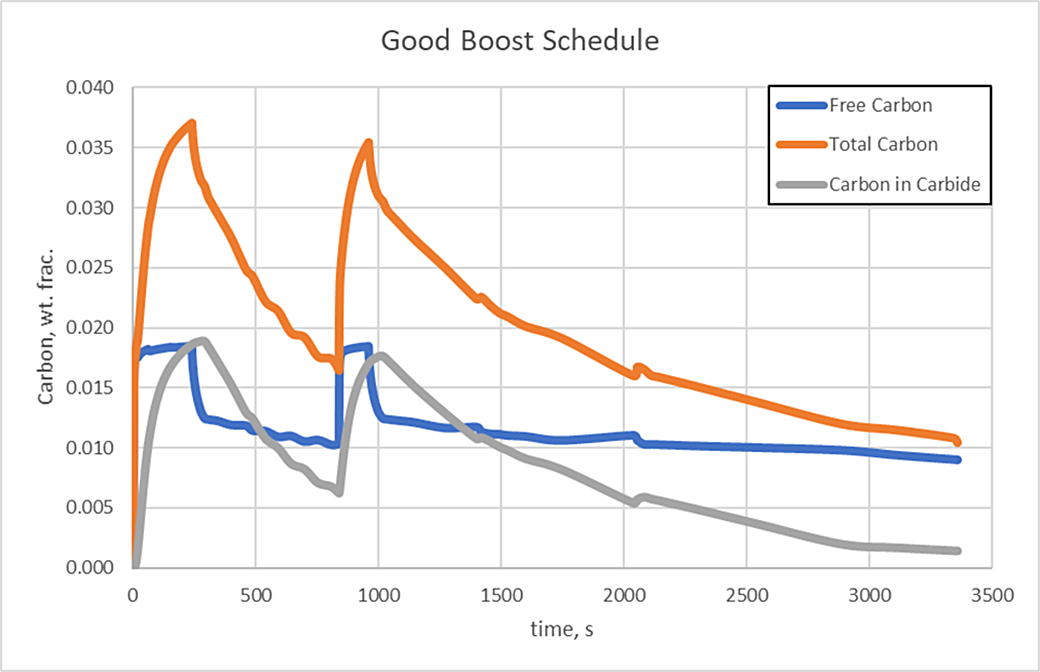
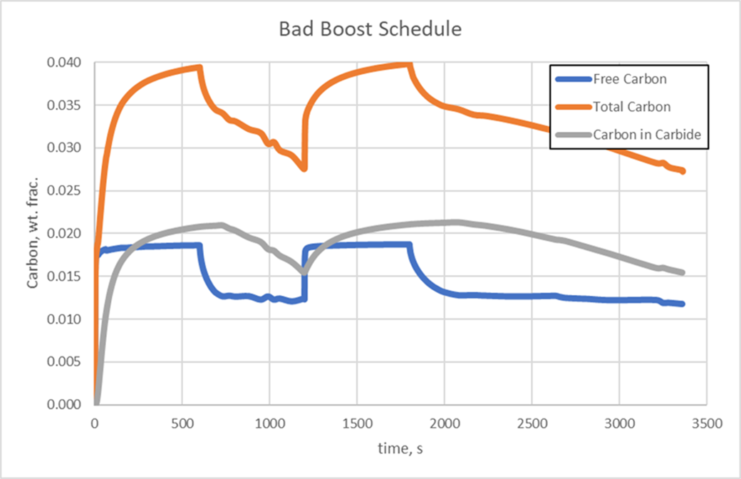
It is evident that the carbides from the poorly designed boost steps are becoming thermodynamically stable and will most likely not dissolve fully at the carburizing temperature, whereas the good schedule sees carbides forming during the boost step and then nearly dissolving during the diffuse steps. Steps could continue to be added in this manner until the required case depth and carbon profile are achieved.
To gather the required data for modeling carbide formation and dissolution behavior, experiments must be conducted. The experiments should be performed in vessels that will be used for production, as the injection and removal of gas will vary depending on the equipment. The transient behavior of the carbon flux on the part surface must be described by the model. Generally, cylindrical coupons are used, with various boost and diffuse times. The idea is to capture carbide behavior at different times of the process, as well as the carbon diffusivity through the austenite matrix. The carbon profile of the coupon is then determined by carefully machining thin layers off the cylinder, collecting the chips from each layer, and performing a LECO analysis. Alternatively, carbon levels can be measured by mass spectrometer. The measurements report the total carbon, a combination of carbon in the matrix and carbon in carbide form, so that a fitting algorithm must be employed to tease out the carbide kinetics. Metallographically prepared mounted samples are also examined optically, with SEM also being used occasionally, to view the carbides. Microhardness measurements are also made on the samples to compare to the carbon measurements and determine a hardness versus carbon relationship.
While high strength steels have the ability to allow for higher power densities in gears and shafts, they also bring the added complexity of rapid carbide formation during carburizing processes. Modeling these processes provides a means to reduce the possibility of unwanted stable carbide formation. However, simple mass diffusion models are no longer sufficient in describing the carbide formation and dissolution behavior. A model which accounts for such behavior must be employed. The DANTE software contains such a model and can be used to design LPC schedules for high alloy steels with relative ease. By modeling the LPC process, the part designer or heat treater is able to avoid the possible detriments of excessive surface and grain boundary carbides or surface contamination by soot or tar.
References
- L. Nobili, P. Cavallotti and M. Pesetti, “Gas-Carburizing Kinetics of a Low-Alloy Steel,” Metallurgical & Materials Transactions A, v41A, February, 2010, pp 460-469.
- W.D. Forgeng and W.D. Foreng, Jr., “Carbon-Chromium Iron,” Metals Handbook, 8th Edition, vol. 8, ASM, Metals Park, OH, 1973, pp 404.
- G.G. Tibbetts, “Diffusivity of carbon in iron and steels at high temperatures,” Journal of Applied Physics, Vol. 51, pp 4813-4816, 1980.
- C. Wells and R. F. Mehl, Trans. AIME, Vol. 140, 279, 1940.
- S.J. Lee, D. K. Matlock and C.J. van Tyne, “An Empirical Model for Carbon Diffusion in Austenite Incorporating Element Effects,” ISIJ Int., Vol. 51, No. 11, 2011, pp. 1903-1911.


 general practice for CQI-9 and AMS2750E")


