


Quench hardening of steel components requires the components to be heated to a temperature such that the solid-state crystal structure of the material changes from a body-centered cubic structure, generally containing some form of carbides, to a face-centered cubic structure with the carbides dissolved within the crystal structure. The heated steel component is then rapidly cooled, with the face-centered cubic structure transforming to either a body-centered cubic structure with carbides or to a body-centered tetragonal with supersaturated carbon locked in the crystal lattice. The final structure obtained after cooling to room temperature is determined by the steel’s alloy content and cooling rate. During this process, there exists the possibility to generate plastic strain, resulting in a final shape which differs, sometimes significantly, from the shape it began with.
For a quench hardening process of a steel component, the high cooling rate, and possibly a high heating rate, can generate strains from the steep temperature gradients near the surface of the part. These thermal strains are due to a material’s natural response to a change in internal energy. As thermal energy is added to the material, its internal energy is raised, and its volume increases as the crystal lattice expands ever so slightly. The opposite then occurs as thermal energy is removed during quenching. If the stresses induced on surrounding material of a different temperature reach a certain value, plastic strain is generated. The other phenomenon that can lead to plastic strain during a quench hardening process is the transformation from one solid-state phase to another. The generation of plastic strains from phase transformations is also related to volume differences between adjacent material in the part. Generally, plastic strains generated from phase transformations are greater than those generated from thermal gradients.
This article will explore, using the heat treatment simulation software DANTE, thermal and transformation strains of a carburized, AISI 4120 steel ring at several locations. The process modeled consists of gas carburization, transfer from the carburization furnace to the oil tank, quenching in oil, and cooling to room temperature. Figure 1(A) shows the meshed, axisymmetric finite-element model. Fine elements near the surface are required to properly describe the carbon and thermal gradients, and their subsequent effect on phase transformations and stress. The ring has an inner diameter of 80 mm, an outer diameter of 120 mm, and a height of 60 mm. Figure 1(B) shows the locations that will be evaluated in the model and the nomenclature used. The locations consist of two surface points, one at mid-height and the other at the corner; two points at the effective case depth of 1.0 mm, one at mid-height and the other at the corner; and one point in the core.
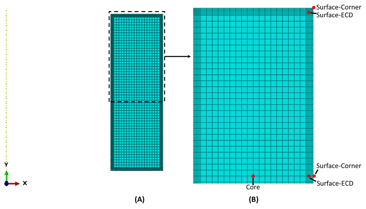
Figure 2 compares the predicted effective plastic strain generated from thermal gradients only to the effective plastic strain generated from a combination of thermal and phase transformation gradients. The effective plastic strain is a magnitude only value and is calculated in the same manner as the von Mises stress. Being independent of tensile or compressive strain, the effective plastic strain is cumulative and is a good measure of the total strain experienced by a component. The results reported as “with Phase Change,” the solid lines, are a combination of plastic strains and used DANTE’s material database data for AISI 4100 series steel, including thermal, mechanical, and phase transformation parameters. The results reported as “No Phase Change,” the dashed lines, used the same DANTE material database data, though the phase transformation parameters were ignored, resulting in no phase change from the initial microstructure of ferrite/pearlite to austenite.
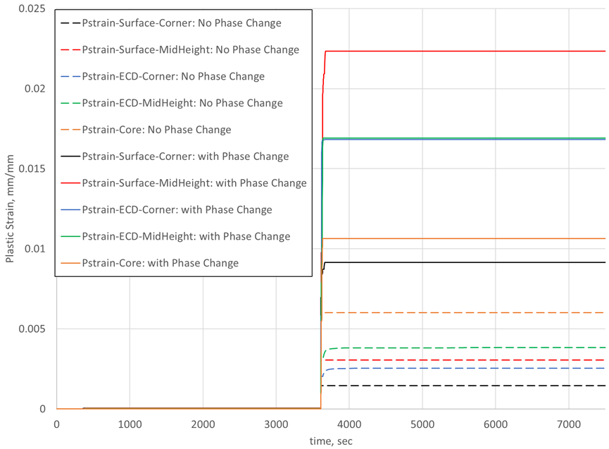
From Figure 2, it is clear that the phase transformations are responsible for most of the plastic strain experienced by this component. Generally, the plastic strain in this example is approximately a full magnitude greater when considering the phase transformations. The exception is the core, where the material does not undergo the stress reversals, and is not subjected to the steep gradients, experienced near the surface. In order to see the effects of heating and cooling on the plastic strain, Figure 2 is divided into these two processing steps.
Figure 3 shows the heating step of the process from Figure 2. The heating step for the model assumed the room temperature part was placed in a preheated radiant tube batch furnace. Even without any attempt to control the heating rate, the thermal gradients from heating in this case were not enough to cause any plastic strain in the initial microstructure. No plastic strain from heating is not always the case, as part geometry can create stress concentrators which can significantly affect the strains witnessed by the part. For simple shapes, however, thermal gradients from heating rarely result in plastic strain. The transformation from a ferritic/pearlitic microstructure to an austenitic microstructure, on the other hand, does create plastic strain on and near the surface, as shown in Figure 3. The core does not undergo any plastic strain from the austenite transformation and was removed from the plot to better illustrate the “No Phase Change” condition.

Figure 4 shows the cooling portion of the process from Figure 2, including the transfer step and quenching. The first noticeable difference between heating and cooling, with respect to plastic strain, is that quenching can generate plastic strain from the thermal stresses alone. Even the core undergoes plastic strain from the thermal gradients, and actually has the most strain when phase transformations are not considered. However, the phase transformation from austenite generates a significant amount of strain. The core has the smallest difference between the two cases, due to the lack of stress reversals experienced by material closer to the surface as the part undergoes phase transformations, but phase transformations still account for a 75 percent increase in the core effective plastic strain. The largest strain is witnessed by the surface of the ring at mid-height and is seven times greater when phase transformations are considered.
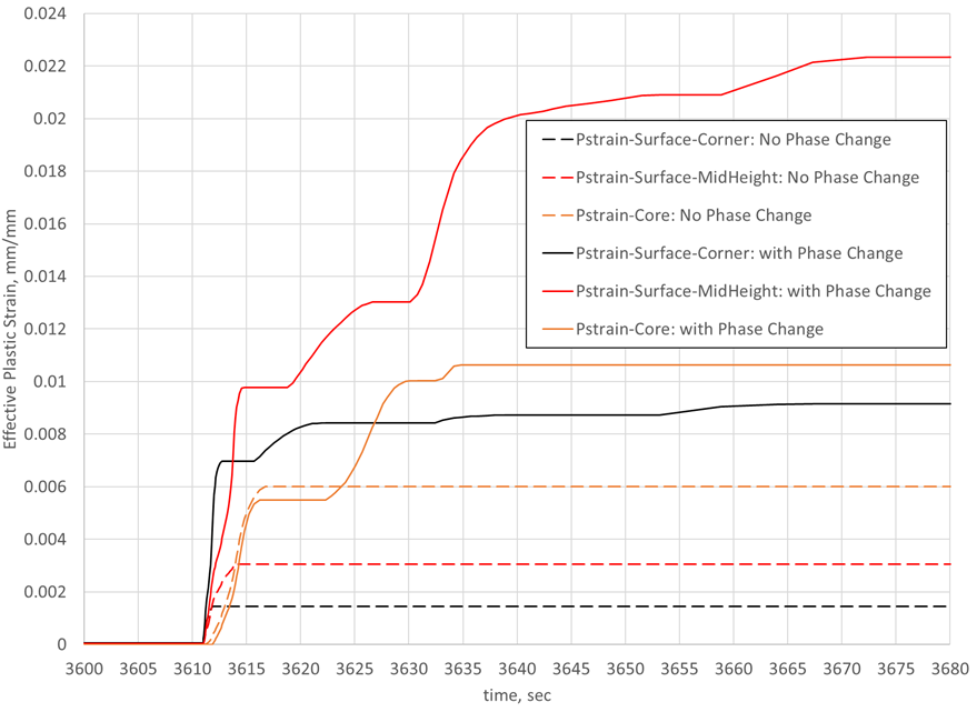
The large amount of plastic strain on the surface at mid-height can be attributed to the influence of carbon on the phase transformation timing. Since the surface has the highest carbon concentration, it will transform to martensite last. This means the strain from the austenite to martensite transformation on the surface changed the strain from 0.021 mm/mm to the final value of 0.0225 mm/mm. All prior plastic strain is due to the influence of material volume change in locations below the surface.
One thing to note is that the plastic strain from cooling will be greater for the case considering phase transformations since the strength of austenite is less than that of ferrite/pearlite. This behavior is clearly visible in Figure 4. Referencing the “Surface-MidHeight” values, without considering phase changes, the ferrite/pearlite strains 0.003 mm/mm due to thermal strains only. Whereas, by considering phase transformations, the austenite strains 0.01 mm/mm due to thermal strains only. Following the “Pstrain-Surface-MidHeight: with Phase Change” data, the jump from 0.01 mm/mm to 0.013 mm/mm is due to the transformation of the base carbon material below the carbon case, the gradual increase from 0.013 mm/mm to 0.021 mm/mm is due to the transformation in the carbon case, and the final increase is from the transformation at the surface. Since DANTE uses rate-based transformation models, results can be viewed throughout the entire process, and the causes of strains are easily discernible.
In summary, quench hardening of steel alloys is a dynamic phenomenon that involves multiple local stress reversals due to thermal expansion differences and phase volumetric differences, and both must be considered to accurately predict part distortion and residual stress in the final part. DANTE has been shown to accurately predict these strains and can be a powerful tool when evaluating the response of a steel component to a particular heat-treatment process.


 general practice for CQI-9 and AMS2750E")


